EP2505902A2 - Shape tube for district heating heat pipe having shear control ring and the method thereof - Google Patents
Shape tube for district heating heat pipe having shear control ring and the method thereof Download PDFInfo
- Publication number
- EP2505902A2 EP2505902A2 EP11181781A EP11181781A EP2505902A2 EP 2505902 A2 EP2505902 A2 EP 2505902A2 EP 11181781 A EP11181781 A EP 11181781A EP 11181781 A EP11181781 A EP 11181781A EP 2505902 A2 EP2505902 A2 EP 2505902A2
- Authority
- EP
- European Patent Office
- Prior art keywords
- pipe
- shear control
- control ring
- internal pipe
- shear
- Prior art date
- Legal status (The legal status is an assumption and is not a legal conclusion. Google has not performed a legal analysis and makes no representation as to the accuracy of the status listed.)
- Granted
Links
Images


Classifications
-
- F—MECHANICAL ENGINEERING; LIGHTING; HEATING; WEAPONS; BLASTING
- F16—ENGINEERING ELEMENTS AND UNITS; GENERAL MEASURES FOR PRODUCING AND MAINTAINING EFFECTIVE FUNCTIONING OF MACHINES OR INSTALLATIONS; THERMAL INSULATION IN GENERAL
- F16L—PIPES; JOINTS OR FITTINGS FOR PIPES; SUPPORTS FOR PIPES, CABLES OR PROTECTIVE TUBING; MEANS FOR THERMAL INSULATION IN GENERAL
- F16L43/00—Bends; Siphons
- F16L43/02—Bends; Siphons adapted to make use of special securing means
-
- F—MECHANICAL ENGINEERING; LIGHTING; HEATING; WEAPONS; BLASTING
- F16—ENGINEERING ELEMENTS AND UNITS; GENERAL MEASURES FOR PRODUCING AND MAINTAINING EFFECTIVE FUNCTIONING OF MACHINES OR INSTALLATIONS; THERMAL INSULATION IN GENERAL
- F16L—PIPES; JOINTS OR FITTINGS FOR PIPES; SUPPORTS FOR PIPES, CABLES OR PROTECTIVE TUBING; MEANS FOR THERMAL INSULATION IN GENERAL
- F16L59/00—Thermal insulation in general
- F16L59/14—Arrangements for the insulation of pipes or pipe systems
- F16L59/16—Arrangements specially adapted to local requirements at flanges, junctions, valves or the like
- F16L59/22—Arrangements specially adapted to local requirements at flanges, junctions, valves or the like adapted for bends
-
- F—MECHANICAL ENGINEERING; LIGHTING; HEATING; WEAPONS; BLASTING
- F16—ENGINEERING ELEMENTS AND UNITS; GENERAL MEASURES FOR PRODUCING AND MAINTAINING EFFECTIVE FUNCTIONING OF MACHINES OR INSTALLATIONS; THERMAL INSULATION IN GENERAL
- F16L—PIPES; JOINTS OR FITTINGS FOR PIPES; SUPPORTS FOR PIPES, CABLES OR PROTECTIVE TUBING; MEANS FOR THERMAL INSULATION IN GENERAL
- F16L59/00—Thermal insulation in general
- F16L59/10—Bandages or covers for the protection of the insulation, e.g. against the influence of the environment or against mechanical damage
-
- F—MECHANICAL ENGINEERING; LIGHTING; HEATING; WEAPONS; BLASTING
- F16—ENGINEERING ELEMENTS AND UNITS; GENERAL MEASURES FOR PRODUCING AND MAINTAINING EFFECTIVE FUNCTIONING OF MACHINES OR INSTALLATIONS; THERMAL INSULATION IN GENERAL
- F16L—PIPES; JOINTS OR FITTINGS FOR PIPES; SUPPORTS FOR PIPES, CABLES OR PROTECTIVE TUBING; MEANS FOR THERMAL INSULATION IN GENERAL
- F16L9/00—Rigid pipes
- F16L9/18—Double-walled pipes; Multi-channel pipes or pipe assemblies
-
- F—MECHANICAL ENGINEERING; LIGHTING; HEATING; WEAPONS; BLASTING
- F24—HEATING; RANGES; VENTILATING
- F24D—DOMESTIC- OR SPACE-HEATING SYSTEMS, e.g. CENTRAL HEATING SYSTEMS; DOMESTIC HOT-WATER SUPPLY SYSTEMS; ELEMENTS OR COMPONENTS THEREFOR
- F24D10/00—District heating systems
-
- F—MECHANICAL ENGINEERING; LIGHTING; HEATING; WEAPONS; BLASTING
- F16—ENGINEERING ELEMENTS AND UNITS; GENERAL MEASURES FOR PRODUCING AND MAINTAINING EFFECTIVE FUNCTIONING OF MACHINES OR INSTALLATIONS; THERMAL INSULATION IN GENERAL
- F16L—PIPES; JOINTS OR FITTINGS FOR PIPES; SUPPORTS FOR PIPES, CABLES OR PROTECTIVE TUBING; MEANS FOR THERMAL INSULATION IN GENERAL
- F16L2201/00—Special arrangements for pipe couplings
- F16L2201/30—Detecting leaks
-
- Y—GENERAL TAGGING OF NEW TECHNOLOGICAL DEVELOPMENTS; GENERAL TAGGING OF CROSS-SECTIONAL TECHNOLOGIES SPANNING OVER SEVERAL SECTIONS OF THE IPC; TECHNICAL SUBJECTS COVERED BY FORMER USPC CROSS-REFERENCE ART COLLECTIONS [XRACs] AND DIGESTS
- Y02—TECHNOLOGIES OR APPLICATIONS FOR MITIGATION OR ADAPTATION AGAINST CLIMATE CHANGE
- Y02E—REDUCTION OF GREENHOUSE GAS [GHG] EMISSIONS, RELATED TO ENERGY GENERATION, TRANSMISSION OR DISTRIBUTION
- Y02E20/00—Combustion technologies with mitigation potential
- Y02E20/14—Combined heat and power generation [CHP]
Definitions
- the present application relates to a shape tube for district heating heat pipe having shear control ring, more specifically, a shape tube for district heating heat pipe having shear control ring for dispersing shear stress, delivered to heat insulators, by applying shear control ring(SCR) to the curves of the internal pipe of curvedly bent heat pipes.
- SCR shear control ring
- Heat pipes refer to heat transfer facilities for supplying heat for district cooling and heating and are used to deliver heat for district cooling and heating, generated in heat generation facilities, to user mechanical facilities.
- Heat supply pipes are currently used as dual insulated pipes, not single insulated pipes in the nation, and heat pipes are commonly used as dual insulated pipes for the reasons of insulation, economics, etc., referring to underground pipelines.
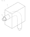
- Fig. 1 illustrates the structure of general dual insulated pipes, comprising: internal pipe(1) made with steel; heat insulator(3) like polyurethane; external pipe(5) made with steel or synthetic resins; and leakage sensing line(7).
- the object of the present application is to provide a shape tube for district heating heat pipe having shear control ring for dispersing shear stress, delivered to a heat insulator, by applying shear control ring(SCR) to curves of the internal pipe of heat pipes bent with constant curvature.
- the present invention is characterized by comprising: an internal pipe, bent with constant curvature, connecting the district heating heat pipe and both ends and flowing medium-temperature hot water inside the internal pipe; an external pipe forming a space and inserting the internal pipe inside, having large diameter than that of the internal pipe; a heat insulator foamed in the space between the internal pipe and the external pipe; and a shear control ring combined to the curves of the internal pipe.
- a spacer maintaining the above space when assembly is further comprised between the internal pipe and the external pipe.
- a leakage sensing line longitudinally installed between the internal pipe and the external pipe and fixed by the heat insulator is further comprised.
- the shear control ring made with metal, has an inside diameter which presses the internal pipe, and is installed by N-numbers.
- the N refers to odd numbers.
- one shear control ring is installed to the center line (C1) of the curves when installing one shear control ring to the curves of the internal pipe.
- one of shear control rings is installed to the center line (C1) of the curves and the rest of shear control rings is formed toward any one point (P1), extended from the center line (C1) of the curves, having the same angle in both directions, respectively.
- the shear control ring has a height wherein the shear control ring is not contacted with the inner side of the external pipe.
- shear control ring is combined by TIG welding to the curves of the internal pipe.
- the method for manufacturing the shape tube for district heating heat pipe having shear control ring of the present invention comprises processes of: manufacturing the shear control ring having a diameter pressed in the external side of the internal pipe by cutting a hollow metal pipe or plate with a cutter; sticking the shear control ring by TIG welding after pressing the shear control ring in the curves of the internal pipe; assembling and inserting the internal pipe, to which the shear control ring is stuck, into the external pipe; and foaming the heat insulator by filling the heat insulator between the external pipe and the internal pipe.
- the sticking process further performs liquid penetrant non-destructive testing after sticking the shear control ring.
- the effect is to prevent transform in heat pipes in advance by installing shear control rings in the curves of the internal pipe of heat pipes bent with constant curvature and dispersing shear stress, delivered to a heat insulator.
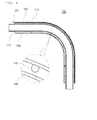
- Fig. 3 is a skew drawing showing the constitution of shape tube for district heating heat pipe having shear control ring
- Fig. 4 is a sectional drawing of Fig. 3
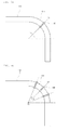
- Figs. 5a and 5b are side views showing the constitution of internal pipes of shape tube for district heating heat pipe having shear control ring according to the present invention.
- a shape tube for district heating heat pipe having shear control ring comprises an internal pipe (110), an external pipe (120), a heat insulator(130), and a shear control ring (140).
- the internal pipe (110) made with metal, comprises a curve (111) bent with constant curvature, wherein both ends are connected to the district heating heat pipes(not illustrated) and medium-temperature hot water is flowed into the inside.
- the internal pipe (110) further includes a plurality of spacers (113) to external sides.
- the external pipe (120) made with metal or synthetic resins, has larger diameter than that of the internal pipe (110) for comprising a space (121) inside when inserting the internal pipe (110), wherein a gap is maintained by the spacer (113) with inserting the internal pipe (110) to the inside center.
- the external pipe (120) further includes the leakage sensing line (123) longitudinally installed inside the external pipe (120) and fixed by the heat insulator (130).
- the heat insulator (130), made with polyurethane foam, is filled in the space (121) between the external side of the internal pipe (110) and the internal side of the external pipe (120).
- the shear control ring (140) made with same or different metal comparing the internal pipe, is inserted to the curves (111) of the internal pipe (110) and is combined by TIG welding.
- the shear control ring (140) is installed in the center line (C1) of the curves (111) when installing one shear control ring to the curves (111) of the internal pipe (110). Further, as illustrated in Fig.
- shear control rings (140) when installing more than three shear control rings (140) to the curves (111) of the internal pipe (110), one of shear control rings is installed to the center line (C1) of the curves (111) and the rest of shear control rings is formed toward any one point(P1), extended from the center line(C1) of the curves (111), having the same angle ( ⁇ ) in both directions, respectively. Furthermore, it is desirable that the shear control ring (140) has a height wherein the shear control ring is not contacted with the inner side of the external pipe (120).
- the basic principle for improving shear strength of the heat insulator by the shear control ring is as follows:
- curved flow passages such as (a) and (b) in Fig. 6 may be considered in order to explain the principle of the method for reducing shear stress applied to the heat insulator through application of the shear control ring suggested in the present invention.
- Fig. 6 is a drawing showing the fluid flow in curved flow passages depending on dam in shape tubes for designing shear control rings according to the present invention.
- FIG. 6 illustrates stream lines of fluid running in curved flow passages in which no dam is installed. According to basic hydrodynamic principles, it can be seen that fluid speed is radially constant in entrance points 1 of flow path, and exit point 3 of flow path. Since there is no obstacle which blocks flow, the fluid running in a pipe has stream lines which are parallel to the shape of flow passages in any points, as indicated with arrow lines in the pipe.
- a dam disturbing fluid flow is installed in the curved section in flow passages.
- the fluid speed in entrance points 1 and exit point 3 is radially constant same as the condition with no dam under the condition that there is enough distance.
- the stream line running in the pipe is not parallel to the shape of the flow passage and becomes twisted. Since the dam is installed inside the pipe, the dam is largely affected at a radially inward position while it is weakly affected at a radially outward position. That is, the radially-innermost dotted stream line is flowing through the most winding path and the stream line keeps the original shape in the outward direction.
- the speed of the radially-innermost fluid in curved section of flow path is increased by dam installment. That is, in case of flow path with no dam as shown in (a) of Fig. 6 , the speed gap (length of stream line) of the radially-innermost dotted stream line and the radially-outermost continuous (non-broken) stream line is big in point 2 and thus, the shear force is increased. However, in case of the dam installment as shown in (b) of Fig. 6 , the speed gap of point 2 is radially reduced by increase of speed (length of stream line) of the dotted stream line, and this reduces radial shear force of fluid applying to the side of the curved section.
- the shear control ring reduces differences of shear force(fluid speed) distributed in the heat insulator (fluid) between steel pipes and external pipes (flow path). Further, the difference reduction of radial shear force enables to reduce shear stress distributed in the heat insulator.
- Fig. 7 is a drawing comparing distribution of shearing stress of the heat insulator depending on shear control rings according to the present invention.
- (a) and (b) in Fig. 7 are the examples showing effects of the shear control ring, illustrating structure analysis of the maximum shear stress of the heat insulator depending on installment of shear control rings for 125A diameters.
- the maximum shear stress is radially generated inside (the part connected to the internal pipe), mainly formed in a thin area parallel to the curved shape of the bend.
- Fig. 8 is a drawing regarding detailed modeling of bend comprising shear control rings.
- number (A), height (B) and thickness (C) of the shear control ring are determined as factors and these are analyzed through three levels.
- the example of the applied shape is illustrated in Fig. 8 and application values generated on the basis of definitions and levels of factors, selected in Table 1, as below, are summarized.
- values depending on levels of each factor are selected, considering installable values in figure conditions of previous heat pipes.
- the height of the shear control ring is determined in consideration of restriction by shapes and sizes of the external pipe for each diameter.
- Table 3 summarizes the maximum shear stress and improvement rate of the bend specifications of optimum shear control ring suggested by the present specifications, applying foam pads, and the present invention. It is anticipated that the shear control ring has effects on strength improvement, reducing maximum shear stress of the heat insulator by 20% - 40% than the previous one.
- the shear control ring (140) having a diameter pressed in the external side of the internal pipe (110) is manufactured by cutting a hollow metal pipe or plate in accordance with the predesigned size with a cutter(5100).
- the shear control ring (140) is stuck by TIG welding after pressing the shear control ring in the curves (111) of the internal pipe (110) (S110). At this time, the curves (111) of the internal pipe (110) was preprocessed, and liquid penetrant non-destructive testing is further performed to check if there is a leakage after sticking the shear control ring (140).
- the internal pipe (110) attached to the shear control ring (140) is inserted and assembled to the external pipe (120) (S120).
- the external pipe (120) was already designed in the bent type to insert the internal pipe (110), and the spacer (113) and the leakage sensing line (123) are installed in the internal pipe (110).
- the heat insulator (130) is filled and foamed between the external pipe (120) and the internal pipe (110) (S130) .
Landscapes
- Engineering & Computer Science (AREA)
- General Engineering & Computer Science (AREA)
- Mechanical Engineering (AREA)
- Physics & Mathematics (AREA)
- Thermal Sciences (AREA)
- Chemical & Material Sciences (AREA)
- Combustion & Propulsion (AREA)
- Thermal Insulation (AREA)
- Rigid Pipes And Flexible Pipes (AREA)
- Pipe Accessories (AREA)
Abstract
Description
- The present application relates to a shape tube for district heating heat pipe having shear control ring, more specifically, a shape tube for district heating heat pipe having shear control ring for dispersing shear stress, delivered to heat insulators, by applying shear control ring(SCR) to the curves of the internal pipe of curvedly bent heat pipes.
- In the 1920s, district heating system was first launched to overcome air pollution due to population growth in cities and save energy in Europe.
- Heat pipes refer to heat transfer facilities for supplying heat for district cooling and heating and are used to deliver heat for district cooling and heating, generated in heat generation facilities, to user mechanical facilities.
- Materials for district heating heat pipes were less effective by low insulation effect due to use of concrete duct in the 1920s, when the development of district heating was just started. However, in the 1960s, district heating system was started in earnest by developing factory manufactured insulated pipes and was distributed all over the world.
- Heat supply pipes are currently used as dual insulated pipes, not single insulated pipes in the nation, and heat pipes are commonly used as dual insulated pipes for the reasons of insulation, economics, etc., referring to underground pipelines.
-
Fig. 1 illustrates the structure of general dual insulated pipes, comprising: internal pipe(1) made with steel; heat insulator(3) like polyurethane; external pipe(5) made with steel or synthetic resins; and leakage sensing line(7). - Since district heating industry was first introduced to the nation in the early 1980s, it has been remarkably developed in the quantitative or qualitative aspects for a short period. At this time, the appearance of housing problem, occurred by centralization of population in industrialization, and energy effectiveness, which comes from increase of the amount of energy, contributes to the spread of the district heating industry.
- However, the field of heat pipes technology has not yet been reached to standardization worldwide. Moreover, since Korea has traditionally preferred intermittent heating of Korean floor heating system, the gap in temperature change of district heating water is big and thus, there is a difficulty in operating heat pipes.
- Heat pipes, laid underground, generate transverse strain in the end of bends by working loads such as compressive force like temperature of medium-temperature hot water flowing inside steel pipe, expansive force by pressure, frictional force and reaction against external pipes and soil.
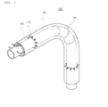
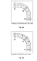
- Particularly, it may be possible to cause damage occurred by force and displacement since shape tubes, bent with constant curvature, among fittings of heat pipes are the structurally weakest part when generating heat expansion by shape condition. Thus, to prevent this matter, as illustrated in
Figs. 2a and2b , newly-built absorber(foam pads) (8) or duct(9) is adhered to the external pipe (5) of shape tubes. - However, as times goes by, such newly-built absorbers are pressed by thermal expansion force and subgrade reaction, resulting in loss of their own functions. Thus, this comes to the reasons for the decrease of heat pipes' life, unstable structures, pipe damages, etc. Also, because of piping condition depending on ground or installed obstacles, it is inevitable that there would be space restriction. Therefore, installed ducts cause low practicality.
- To solve such problems, stable development of heat pipes toward thermal expansion force have been rising without considering newly-built absorbers and ducts basically.
- To achieve the above request, the object of the present application is to provide a shape tube for district heating heat pipe having shear control ring for dispersing shear stress, delivered to a heat insulator, by applying shear control ring(SCR) to curves of the internal pipe of heat pipes bent with constant curvature.
- To achieve the above object, the present invention is characterized by comprising: an internal pipe, bent with constant curvature, connecting the district heating heat pipe and both ends and flowing medium-temperature hot water inside the internal pipe; an external pipe forming a space and inserting the internal pipe inside, having large diameter than that of the internal pipe; a heat insulator foamed in the space between the internal pipe and the external pipe; and a shear control ring combined to the curves of the internal pipe. Here, a spacer maintaining the above space when assembly is further comprised between the internal pipe and the external pipe.
- Further, a leakage sensing line longitudinally installed between the internal pipe and the external pipe and fixed by the heat insulator is further comprised.
- Furthermore, the shear control ring, made with metal, has an inside diameter which presses the internal pipe, and is installed by N-numbers.
- Moreover, the N refers to odd numbers.
- In addition, one shear control ring is installed to the center line (C1) of the curves when installing one shear control ring to the curves of the internal pipe.
- Additionally, when installing more than three shear control rings to the curves of the internal pipe, one of shear control rings is installed to the center line (C1) of the curves and the rest of shear control rings is formed toward any one point (P1), extended from the center line (C1) of the curves, having the same angle in both directions, respectively.
- Further, the shear control ring has a height wherein the shear control ring is not contacted with the inner side of the external pipe.
- Furthermore, the shear control ring is combined by TIG welding to the curves of the internal pipe.
- Also, the method for manufacturing the shape tube for district heating heat pipe having shear control ring of the present invention comprises processes of: manufacturing the shear control ring having a diameter pressed in the external side of the internal pipe by cutting a hollow metal pipe or plate with a cutter; sticking the shear control ring by TIG welding after pressing the shear control ring in the curves of the internal pipe; assembling and inserting the internal pipe, to which the shear control ring is stuck, into the external pipe; and foaming the heat insulator by filling the heat insulator between the external pipe and the internal pipe.
- Moreover, the sticking process further performs liquid penetrant non-destructive testing after sticking the shear control ring.
- According to a shape tube for district heating heat pipe having shear control ring constituted as above, the effect is to prevent transform in heat pipes in advance by installing shear control rings in the curves of the internal pipe of heat pipes bent with constant curvature and dispersing shear stress, delivered to a heat insulator.
-
-
Fig. 1 is a skew drawing showing the constitution of general heat pipe. -
Figs. 2a and2b are skew drawings showing the constitution of shape tube for general heat pipe. -
Fig. 3 is a skew drawing showing the constitution of shape tube for district heating heat pipe having shear control ring. -
Fig. 4 is a sectional drawing ofFig. 3 . -
Figs. 5a and 5b are side views showing the constitution of internal pipes of shape tube for district heating heat pipe having shear control ring according to the present invention. -
Fig. 6 is a drawing showing the fluid flow in curved flow passages depending on dam in shape tubes for designing shear control rings according to the present invention. -
Fig. 7 is a drawing comparing distribution of shearing stress of a heat insulator depending on shear control rings according to the present invention. -
Fig. 8 is a drawing regarding detailed modeling of bend comprising shear control rings. -
Fig. 9 is a process flow diagram for explaining the process of manufacturing shape tubes for district heating heat pipes having shear control rings according to the present invention. - Hereinafter, an explanation of the method for constructing precast coping for bridge according to the present invention will be given with reference to the attached drawings.
- A detailed explanation on the known functions and configurations related to this invention will be avoided for the brevity of the description. And, the terms as will be mentioned below are used by the functions defined in this invention, which is of course varied in accordance with the intension or rules of a user or operator. Therefore, the definition of the terms should be based upon the contents of the description of the invention.
-
Fig. 3 is a skew drawing showing the constitution of shape tube for district heating heat pipe having shear control ring;Fig. 4 is a sectional drawing ofFig. 3 ; andFigs. 5a and 5b are side views showing the constitution of internal pipes of shape tube for district heating heat pipe having shear control ring according to the present invention. - Referring to
Figs. 3 to 5b , a shape tube for district heating heat pipe having shear control ring according to the present invention comprises an internal pipe (110), an external pipe (120), a heat insulator(130), and a shear control ring (140). - First, the internal pipe (110), made with metal, comprises a curve (111) bent with constant curvature, wherein both ends are connected to the district heating heat pipes(not illustrated) and medium-temperature hot water is flowed into the inside. Here, it is desirable that the internal pipe (110) further includes a plurality of spacers (113) to external sides.
- Further, the external pipe (120), made with metal or synthetic resins, has larger diameter than that of the internal pipe (110) for comprising a space (121) inside when inserting the internal pipe (110), wherein a gap is maintained by the spacer (113) with inserting the internal pipe (110) to the inside center. Here, the external pipe (120) further includes the leakage sensing line (123) longitudinally installed inside the external pipe (120) and fixed by the heat insulator (130).
- Furthermore, the heat insulator (130), made with polyurethane foam, is filled in the space (121) between the external side of the internal pipe (110) and the internal side of the external pipe (120).
- Meanwhile, the shear control ring (140), made with same or different metal comparing the internal pipe, is inserted to the curves (111) of the internal pipe (110) and is combined by TIG welding. The shear control ring (140) has an inner diameter which presses the internal pipe (110) and is installed by N-numbers(N=odd numbers). Here, as illustrated in
Fig. 5a , the shear control ring (140) is installed in the center line (C1) of the curves (111) when installing one shear control ring to the curves (111) of the internal pipe (110). Further, as illustrated inFig. 5b , when installing more than three shear control rings (140) to the curves (111) of the internal pipe (110), one of shear control rings is installed to the center line (C1) of the curves (111) and the rest of shear control rings is formed toward any one point(P1), extended from the center line(C1) of the curves (111), having the same angle (θ) in both directions, respectively. Furthermore, it is desirable that the shear control ring (140) has a height wherein the shear control ring is not contacted with the inner side of the external pipe (120). - The design of a shape tube for district heating heat pipe having shear control ring according to the present invention is detailedly explained by referring to enclosed drawings as follows:
- The study on shape optimum design of the specifications of the shear control ring(SCR) according to the present invention was conducted.
- First, the basic principle of the method for reducing maximum shear strength generated in the heat insulator by applying the shear control ring is illustrated and explained, and figures of optimum shear control ring for each pipe's diameter are calculated by applying Taguchi method, one of designs of experiment.
- The basic principle for improving shear strength of the heat insulator by the shear control ring is as follows:
- Heat pipes, laid underground, generate transverse strain in the end of bends by working loads such as compressive force like temperature of medium-temperature hot water flowing inside steel pipe, expansive force by pressure, frictional force and reaction against external pipes and soil. Under this condition, it is confirmed that the structurally weakest part of components of shape tubes is shear stress, and shear control rings are set up as one of shape tubes for solving this matter.
- Although each object of the structural mechanics approaches, considering loads of members and stress or displacement, and the hydromechanics approach, considering fluid flow, pressure and speed, is different from those of structures and fluid, there may be similarity in laws of physics that the sum of energy is consistent under given conditions.
- In the above aspect, curved flow passages such as (a) and (b) in
Fig. 6 may be considered in order to explain the principle of the method for reducing shear stress applied to the heat insulator through application of the shear control ring suggested in the present invention.Fig. 6 is a drawing showing the fluid flow in curved flow passages depending on dam in shape tubes for designing shear control rings according to the present invention. - It is assumed that there is arbitrary fluid in flow path; the fluid slowly runs as much as the pressure focused by inertial force(centrifugal force) of the fluid itself may be ignored in curved sections for simplifying matters; and frictional force which applies to the boundary surface between the fluid and the flow path may be ignored.
- Two cases are considered, one that there is no device which blocks the flow of the fluid in flow path, and the other that a dam, disturbing the fluid flow in curved flow passages, i.e., the shear control ring is installed.
(a) inFig. 6 illustrates stream lines of fluid running in curved flow passages in which no dam is installed. According to basic hydrodynamic principles, it can be seen that fluid speed is radially constant inentrance points ① of flow path, andexit point ③ of flow path. Since there is no obstacle which blocks flow, the fluid running in a pipe has stream lines which are parallel to the shape of flow passages in any points, as indicated with arrow lines in the pipe. However, while passing through the curved flow passage, movement distance of one arbitrary point in the fluid is different because of 90 degree curved flow passages. That is, as for point ② running in the curved flow passage in (a) ofFig. 6 , comparing dotted and broken stream lines in the innermost parts of the curved flow passage and continuous (non-broken) stream line in the outermost part of the curved flow passage, the dotted stream line has the slowest fluid speed (which means the shortest distance running in curved sections) and the speed becomes faster toward broken and continuous (non-broken)stream lines. When fluid speed passing through one arbitrary side like point ② becomes radially different, which means that each layer's speed is different, the size of shear force is determined by the difference of the slowest fluid speed and the fastest fluid speed when the shear force is applied to fluid. Therefore, if it may be possible to reduce the difference of the maximum/minimum value of fluid speed passing through arbitrary sides of curved sections, the shear force generated in the fluid may be reduced as long as the radial speed of fluid passing through arbitrary sides is constant. - As seen in (b) in
Fig. 6 , a dam disturbing fluid flow is installed in the curved section in flow passages. Although the installed dam changes flow conditions, the fluid speed inentrance points ① andexit point ③ is radially constant same as the condition with no dam under the condition that there is enough distance. Due to the installed dam, the stream line running in the pipe is not parallel to the shape of the flow passage and becomes twisted. Since the dam is installed inside the pipe, the dam is largely affected at a radially inward position while it is weakly affected at a radially outward position. That is, the radially-innermost dotted stream line is flowing through the most winding path and the stream line keeps the original shape in the outward direction. Since the length of the stream line is proportional to fluid speed, the speed of the radially-innermost fluid in curved section of flow path is increased by dam installment. That is, in case of flow path with no dam as shown in (a) ofFig. 6 , the speed gap (length of stream line) of the radially-innermost dotted stream line and the radially-outermost continuous (non-broken) stream line is big in point ② and thus, the shear force is increased. However, in case of the dam installment as shown in (b) ofFig. 6 , the speed gap of point ② is radially reduced by increase of speed (length of stream line) of the dotted stream line, and this reduces radial shear force of fluid applying to the side of the curved section. - The specifications of the shear control ring suggested in the present invention embody the above concepts structurally. Thus, the shear control ring reduces differences of shear force(fluid speed) distributed in the heat insulator (fluid) between steel pipes and external pipes (flow path). Further, the difference reduction of radial shear force enables to reduce shear stress distributed in the heat insulator.
-
Fig. 7 is a drawing comparing distribution of shearing stress of the heat insulator depending on shear control rings according to the present invention.
(a) and (b) inFig. 7 are the examples showing effects of the shear control ring, illustrating structure analysis of the maximum shear stress of the heat insulator depending on installment of shear control rings for 125A diameters. As seen in (a) inFig. 7 , as for the bend with no shear control ring, the maximum shear stress is radially generated inside (the part connected to the internal pipe), mainly formed in a thin area parallel to the curved shape of the bend. Meanwhile, as for (b) inFig. 7 with the shear control ring, it can be seen that the distribution of shear stress is dispersed by cutting the concentrated flow of shear stress simultaneously with widening the relatively high distribution area of shear stress. Also, it can be seen that the generation part of the maximum shear stress moves radially outwards from the parts, connected to the internal pipe and the heat insulator, to the parts, connected to the shear control ring and the heat insulator. - Also, the design of experiment for optimizing the shape of the shear control ring is as follows:
- The objective function of Taguchi method in the present invention is to minimize loss. First, several factors are selected to reduce loss in determining optimal condition of products or processes with using Taguchi method. Secondly, each factor is displayed on orthogonal tables; each level of factors is calculated; and the results are expressed and analyzed as signal-to-noise ratio. Consequentially, the finally selected level is determined as the optimal condition since it may be possible to analyze the level of each factor's influence for reducing loss. Specifically, four diameters such as 800A, 400A, 200A and 125A among currently used diameters are selected and analyzed.
-
Fig. 8 is a drawing regarding detailed modeling of bend comprising shear control rings. - To find the optimal shape of the shear control ring using Taguchi method, number (A), height (B) and thickness (C) of the shear control ring are determined as factors and these are analyzed through three levels. The example of the applied shape is illustrated in
Fig. 8 and application values generated on the basis of definitions and levels of factors, selected in Table 1, as below, are summarized. At this time, values depending on levels of each factor are selected, considering installable values in figure conditions of previous heat pipes. For instance, the height of the shear control ring is determined in consideration of restriction by shapes and sizes of the external pipe for each diameter.TABLE 1 DIAMETER FACTOR DEFINITION LEVEL 1 2 3 800A A NUMBER (N0 ) 1 3 5 B HEIGHT(mm) 20 25 30 C THICKNESS(mm) 50 60 70 400A A NUMBER (N0 ) 1 3 5 B HEIGHT(mm) 20 25 30 C THICKNESS(mm) 25 30 35 200A A NUMBER (N0 ) 1 3 5 B HEIGHT(mm) 12 15.5 19 C THICKNESS(mm) 20 25 30 125A A NUMBER(N0. ) 1 3 5 B HEIGHT(mm) 10.5 14 0 17 5 C THICKNESS(mm) 15.0 20 0 25 0 - The combination of every possible level for each diameter is 27; required degrees of freedom are 2; since the rectangular coordinate, chosen from Taguchi method, is limited, three factors (A, B, C) are displayed by selecting L9(34) orthogonal table in which maximum four factors may be displayed; and the rest is recorded and displayed as e(empty). The only influence on single factors is considered in the present invention and thus, the interaction among factors is not considered.
- In conclusion, it can be seen that effects become increased as much as numbers and sizes of all factors in consideration of all diameters are big, and the key factor in reducing the maximum shear stress of the heat insulator among factors considered in all diameters is the number of the shear control ring. As for slight differences in contribution rates of height and thickness for each diameter, these differences are occurred by the level which may be manufactured when determining levels of factors.
- The final specifications of the shear control ring bend determined through the Taguchi method is shown in Table 2.
TABLE 2 DIAMETER NUMBER. A (N0.) HEIGHT. B (mm) THICKNESS. C (mm) 800A 5 30 70 400A 5 30 35 200A 5 19 30 125A 5 17.5 25 - Table 3 summarizes the maximum shear stress and improvement rate of the bend specifications of optimum shear control ring suggested by the present specifications, applying foam pads, and the present invention. It is anticipated that the shear control ring has effects on strength improvement, reducing maximum shear stress of the heat insulator by 20% - 40% than the previous one.
TABLE 3 DIAMETER PUR SHEAR STRESS(MPa) IMPROVEMENT RATE (%) CURRENT SPECIFICATIONS APPLIED TO FOAM PAD SPECIFICATIONS OF SHEAR CONTROL RING FROM WHICH FOAM PAD IS EXCLUDED 800A 0.36 0.22 -38.9 400A 0.22 0.16 -27.3 200A 0.19 0.14 -26.3 125A 0.13 0.10 -23.1 - The process for manufacturing the shape tube for district heating heat pipe having control ring according to the present invention is detailedly explained by referring to the enclosed drawings as follows:
-
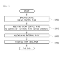
Fig. 9 is a process flow diagram for explaining the process of manufacturing shape tubes for district heating heat pipes having shear control rings according to the present invention. - First, the shear control ring (140) having a diameter pressed in the external side of the internal pipe (110) is manufactured by cutting a hollow metal pipe or plate in accordance with the predesigned size with a cutter(5100).
- Further, the shear control ring (140) is stuck by TIG welding after pressing the shear control ring in the curves (111) of the internal pipe (110) (S110). At this time, the curves (111) of the internal pipe (110) was preprocessed, and liquid penetrant non-destructive testing is further performed to check if there is a leakage after sticking the shear control ring (140).
- Next, the internal pipe (110) attached to the shear control ring (140) is inserted and assembled to the external pipe (120) (S120). At this time, the external pipe (120) was already designed in the bent type to insert the internal pipe (110), and the spacer (113) and the leakage sensing line (123) are installed in the internal pipe (110).
- Furthermore, the heat insulator (130) is filled and foamed between the external pipe (120) and the internal pipe (110) (S130) .
- While the invention has been shown and described with reference to certain preferred embodiments thereof, it will be understood by those skilled in the art that various changes in form and details may be made therein without departing from the spirit and scope of the invention as defined by the appended claims. Therefore, the scope of the invention is defined not by the detailed description of the invention but by the appended claims, and all differences within the scope will be construed as being included in the present invention.
-
110: internal pipe 111: curve 113: spacer 120: external pipe 121: space 123: leakage sensing lines 130: heat insulator 140: shear control ring
Claims (11)
- The shape tube for district heating heat pipe having shear control ring comprising: an internal pipe, bent with constant curvature, connecting the district heating heat pipe and both ends and flowing medium-temperature hot water inside the internal pipe; an external pipe forming a space and inserting the internal pipe inside, having large diameter than that of the internal pipe; a heat insulator foamed in the space between the internal pipe and the external pipe; and a shear control ring combined to the curves of the internal pipe.
- The shape tube according to claim 1, wherein a spacer maintaining the above space when assembly is further comprised between the internal pipe and the external pipe.
- The shape tube according to claim 1 or 2, wherein a leakage sensing line longitudinally installed between the internal pipe and the external pipe and fixed by the heat insulator is further comprised
- The shape tube according to claims 1 to 3, wherein the shear control ring, made with metal, has an inside diameter which presses the internal pipe, and is installed by N-numbers.
- The shape tube according to claims 1 to 4, wherein the N refers to odd numbers.
- The shape tube according to claims 1 to 5, wherein one shear control ring is installed to the center line (C1) of the curves when installing one shear control ring to the curves of the internal pipe.
- The shape tube according to claims 1 to 6, wherein when installing more than three shear control rings to the curves of the internal pipe, one of shear control rings is installed to the center line (C1) of the curves and the rest of shear control rings is formed toward any one standard point (P1), extended from the center line (C1) of the curves, having the same angle in both directions, respectively.
- The shape tube according to claims 1 to 7, wherein the shear control ring has a height wherein the shear control ring is not contacted with the inner side of the external pipe.
- The shape tube according to claims 1 to 8, wherein the shear control ring is combined by TIG welding to the curves of the internal pipe.
- The method for manufacturing the shape tube for district heating heat pipe having shear control ring of claims 1 to 9 comprising processes of: manufacturing the shear control ring having a diameter pressed in the external side of the internal pipe by cutting a hollow metal pipe or plate with a cutter; sticking the shear control ring by TIG welding after pressing the shear control ring in the curves of the internal pipe; assembling and inserting the internal pipe, to which the shear control ring is stuck, into the external pipe; and foaming the heat insulator by filling the heat insulator between the external pipe and the internal pipe.
- The method according to claim 10, wherein the sticking process further performs liquid penetrant non-destructive testing after sticking the shear control ring.
Priority Applications (1)
| Application Number | Priority Date | Filing Date | Title |
|---|---|---|---|
| PL11181781T PL2505902T3 (en) | 2011-03-30 | 2011-09-19 | Shape tube for district heating heat pipe having shear control ring and the method thereof |
Applications Claiming Priority (1)
| Application Number | Priority Date | Filing Date | Title |
|---|---|---|---|
| KR1020110028810A KR101298656B1 (en) | 2011-03-30 | 2011-03-30 | Shape tube for district heating heat pipe having shear control ring |
Publications (3)
| Publication Number | Publication Date |
|---|---|
| EP2505902A2 true EP2505902A2 (en) | 2012-10-03 |
| EP2505902A3 EP2505902A3 (en) | 2013-08-28 |
| EP2505902B1 EP2505902B1 (en) | 2016-02-10 |
Family
ID=44785414
Family Applications (1)
| Application Number | Title | Priority Date | Filing Date |
|---|---|---|---|
| EP11181781.3A Not-in-force EP2505902B1 (en) | 2011-03-30 | 2011-09-19 | Shape tube for district heating heat pipe having shear control ring and the method thereof |
Country Status (5)
| Country | Link |
|---|---|
| EP (1) | EP2505902B1 (en) |
| KR (1) | KR101298656B1 (en) |
| CN (1) | CN102734603B (en) |
| DK (1) | DK2505902T3 (en) |
| PL (1) | PL2505902T3 (en) |
Cited By (3)
| Publication number | Priority date | Publication date | Assignee | Title |
|---|---|---|---|---|
| CN103453281A (en) * | 2013-01-04 | 2013-12-18 | 李宏江 | Normal soft-rigid heat insulation pipeline and manufacturing method thereof |
| CN110472352A (en) * | 2019-08-20 | 2019-11-19 | 大连海事大学 | The starting critical pipe diameter design method of pulsating heat pipe under plumbness |
| WO2019224423A1 (en) * | 2018-05-21 | 2019-11-28 | Valmet Technologies Oy | A coaxial heat transfer tube suitable for a fluidized bed boiler and a method for manufacturing same |
Families Citing this family (7)
| Publication number | Priority date | Publication date | Assignee | Title |
|---|---|---|---|---|
| CN103234098A (en) * | 2013-05-14 | 2013-08-07 | 广西玉林宏江能源科技有限公司 | Manufacturing method of common soft and hard heat insulating pipeline |
| CN104295845A (en) * | 2014-09-26 | 2015-01-21 | 哈尔滨朗格斯特节能科技有限公司 | Crosslinked polyethylene work pipe fitting elbow for directly-buried heat preservation pipe intelligently prefabricated and manufacturing method |
| CN104455877A (en) * | 2014-10-08 | 2015-03-25 | 哈尔滨朗格斯特节能科技有限公司 | Crosslinked polyethylene double-tube tube fitting bend of intelligent prefabricated direct buried heating insulating tube and manufacturing method |
| CN104373730A (en) * | 2014-10-31 | 2015-02-25 | 哈尔滨朗格斯特节能科技有限公司 | Fixing device and method for intelligent prefabricated directly-buried thermal insulation pipe double pipe elbow alarm lines |
| CN107429860A (en) * | 2015-04-09 | 2017-12-01 | Mrp有限公司 | Method for welding insulation pipeline |
| CN113414392B (en) * | 2021-05-11 | 2023-02-17 | 岭东核电有限公司 | Preparation method of special-shaped pipeline based on 3D printing technology |
| CN117020590A (en) * | 2023-10-08 | 2023-11-10 | 核工业西南物理研究院 | Manufacturing method of special pipe with interlayer |
Family Cites Families (11)
| Publication number | Priority date | Publication date | Assignee | Title |
|---|---|---|---|---|
| US2041911A (en) * | 1935-05-25 | 1936-05-26 | Universal Insulation Company | Heat insulation |
| SE434815B (en) * | 1982-02-23 | 1984-08-20 | Lindab Nord Ab | SET FOR MANUFACTURE OF ISOLATED PIPE CONTROL PARTS |
| DE3345371A1 (en) * | 1983-12-15 | 1985-06-27 | kabelmetal electro GmbH, 3000 Hannover | Method for subsequent insulation of a curve of a heat-insulated pipeline |
| DE3506144A1 (en) * | 1985-02-22 | 1986-08-28 | kabelmetal electro GmbH, 3000 Hannover | Process for producing a heat-insulated line pipe |
| US5031665A (en) * | 1989-01-31 | 1991-07-16 | Exxon Research And Engineering Company | Curved pipe section having refractory lining and central section of flexible insulating material |
| CN1067952A (en) * | 1991-06-20 | 1993-01-13 | 广饶县稻庄镇散热器厂 | Glass fibre reinforced plastics jacketed heat insulating pipeline and forming method thereof |
| JP4899808B2 (en) * | 2006-11-09 | 2012-03-21 | Jfeスチール株式会社 | Curved pipe section of heat insulating multi-pipe for superconducting power transmission |
| KR100843341B1 (en) * | 2007-12-05 | 2008-07-03 | 에스이피엔씨 주식회사 | Double heat insulation tube having a fusion layer, its manufacturing method and manufacturing apparatus |
| JP5302036B2 (en) * | 2009-02-10 | 2013-10-02 | 本田技研工業株式会社 | Cylindrical workpiece cutting device |
| CN101629912A (en) * | 2009-08-10 | 2010-01-20 | 西部金属材料股份有限公司 | Determination method of reliability of titanium welding seam of titanium steel composite board equipment |
| WO2011021882A2 (en) * | 2009-08-21 | 2011-02-24 | Yu Hong Keun | Leaking-fluid and pipe-cut sensing device, a production method for the same and a pipe employing the same |
-
2011
- 2011-03-30 KR KR1020110028810A patent/KR101298656B1/en active Active
- 2011-09-09 CN CN201110266878.6A patent/CN102734603B/en not_active Expired - Fee Related
- 2011-09-19 DK DK11181781.3T patent/DK2505902T3/en active
- 2011-09-19 EP EP11181781.3A patent/EP2505902B1/en not_active Not-in-force
- 2011-09-19 PL PL11181781T patent/PL2505902T3/en unknown
Non-Patent Citations (1)
| Title |
|---|
| None |
Cited By (5)
| Publication number | Priority date | Publication date | Assignee | Title |
|---|---|---|---|---|
| CN103453281A (en) * | 2013-01-04 | 2013-12-18 | 李宏江 | Normal soft-rigid heat insulation pipeline and manufacturing method thereof |
| WO2019224423A1 (en) * | 2018-05-21 | 2019-11-28 | Valmet Technologies Oy | A coaxial heat transfer tube suitable for a fluidized bed boiler and a method for manufacturing same |
| US11859911B2 (en) | 2018-05-21 | 2024-01-02 | Valmet Technologies Oy | Coaxial heat transfer tube suitable for a fluidized bed boiler and a method for manufacturing same |
| CN110472352A (en) * | 2019-08-20 | 2019-11-19 | 大连海事大学 | The starting critical pipe diameter design method of pulsating heat pipe under plumbness |
| CN110472352B (en) * | 2019-08-20 | 2022-10-25 | 大连海事大学 | Design method of starting critical diameter of pulsating heat pipe in vertical state |
Also Published As
| Publication number | Publication date |
|---|---|
| EP2505902A3 (en) | 2013-08-28 |
| PL2505902T3 (en) | 2016-08-31 |
| KR101298656B1 (en) | 2013-08-21 |
| CN102734603B (en) | 2014-10-08 |
| CN102734603A (en) | 2012-10-17 |
| DK2505902T3 (en) | 2016-04-11 |
| EP2505902B1 (en) | 2016-02-10 |
| KR20120110747A (en) | 2012-10-10 |
Similar Documents
| Publication | Publication Date | Title |
|---|---|---|
| EP2505902A2 (en) | Shape tube for district heating heat pipe having shear control ring and the method thereof | |
| CN102226487B (en) | Heat-supply three-layer casing system based on countercurrent heat exchange principle | |
| KR100915630B1 (en) | Insulation cover for piping and method for constructing the same | |
| US9377150B2 (en) | Method and apparatus for preserving the long term structural integrity of bonded foam pre-insulated piping systems | |
| Shan et al. | The influence of central regulation methods upon annual heat loss in heating network | |
| CN204704479U (en) | Based on C type section deformation element deep water pipe-in-pipe buckle arrestor | |
| CN204704478U (en) | Based on the deep water pipe-in-pipe buckle arrestor of T-shaped section deformation element | |
| JP6703906B2 (en) | Freezing method | |
| CN108612911B (en) | Direct-buried heat distribution pipeline | |
| CN201265827Y (en) | Energy-saving stand | |
| CN205745646U (en) | Based on CX section deformation element deep water pipe-in-pipe buckle arrestor | |
| CN102296721A (en) | Single-rod square steel tube support with casing and manufacturing method thereof | |
| US20160097566A1 (en) | Cooling system using deep seawater | |
| CN110778794A (en) | Prefabricated polyurethane is adiabatic sliding support of formula of preassembleing for heat preservation pipe | |
| CN104896216A (en) | High-density polyethylene corrugated outer protection pipe and double pipe heat insulation pipeline | |
| CN204176133U (en) | Based on the deep water pipe-in-pipe buckle arrestor of dentation section deformation element | |
| US20070257124A1 (en) | Hydronic radiant flooring heating system | |
| CN203421310U (en) | Heating pipe mechanism capable of preventing stand column from thermal expansion displacement | |
| Kim et al. | Development of a reinforced bend with shear control ring for district heating | |
| CN223755483U (en) | Piping auxiliary components and underfloor heating system | |
| CN104373686A (en) | Fixing method for alarm cables of intelligent crosslinked polyethylene double-pipe insulating pipe reducing pipe fitting | |
| CN220379215U (en) | Process cooling water pre-buried pipeline heat insulation structure in concrete | |
| KR20140042560A (en) | Heat storage slab | |
| US8689839B2 (en) | Apparatus for receiving insulation | |
| CN105443865B (en) | A kind of deep water pipe-in-pipe buckle arrestor based on T-type section deformation element |
Legal Events
| Date | Code | Title | Description |
|---|---|---|---|
| PUAI | Public reference made under article 153(3) epc to a published international application that has entered the european phase |
Free format text: ORIGINAL CODE: 0009012 |
|
| AK | Designated contracting states |
Kind code of ref document: A2 Designated state(s): AL AT BE BG CH CY CZ DE DK EE ES FI FR GB GR HR HU IE IS IT LI LT LU LV MC MK MT NL NO PL PT RO RS SE SI SK SM TR |
|
| AX | Request for extension of the european patent |
Extension state: BA ME |
|
| PUAL | Search report despatched |
Free format text: ORIGINAL CODE: 0009013 |
|
| AK | Designated contracting states |
Kind code of ref document: A3 Designated state(s): AL AT BE BG CH CY CZ DE DK EE ES FI FR GB GR HR HU IE IS IT LI LT LU LV MC MK MT NL NO PL PT RO RS SE SI SK SM TR |
|
| AX | Request for extension of the european patent |
Extension state: BA ME |
|
| RIC1 | Information provided on ipc code assigned before grant |
Ipc: F16L 59/22 20060101AFI20130724BHEP |
|
| 17P | Request for examination filed |
Effective date: 20140225 |
|
| RBV | Designated contracting states (corrected) |
Designated state(s): AL AT BE BG CH CY CZ DE DK EE ES FI FR GB GR HR HU IE IS IT LI LT LU LV MC MK MT NL NO PL PT RO RS SE SI SK SM TR |
|
| GRAP | Despatch of communication of intention to grant a patent |
Free format text: ORIGINAL CODE: EPIDOSNIGR1 |
|
| INTG | Intention to grant announced |
Effective date: 20150806 |
|
| GRAS | Grant fee paid |
Free format text: ORIGINAL CODE: EPIDOSNIGR3 |
|
| GRAA | (expected) grant |
Free format text: ORIGINAL CODE: 0009210 |
|
| AK | Designated contracting states |
Kind code of ref document: B1 Designated state(s): AL AT BE BG CH CY CZ DE DK EE ES FI FR GB GR HR HU IE IS IT LI LT LU LV MC MK MT NL NO PL PT RO RS SE SI SK SM TR |
|
| REG | Reference to a national code |
Ref country code: GB Ref legal event code: FG4D |
|
| REG | Reference to a national code |
Ref country code: AT Ref legal event code: REF Ref document number: 774827 Country of ref document: AT Kind code of ref document: T Effective date: 20160215 Ref country code: CH Ref legal event code: EP |
|
| REG | Reference to a national code |
Ref country code: IE Ref legal event code: FG4D |
|
| REG | Reference to a national code |
Ref country code: DE Ref legal event code: R096 Ref document number: 602011023193 Country of ref document: DE |
|
| REG | Reference to a national code |
Ref country code: DK Ref legal event code: T3 Effective date: 20160408 |
|
| REG | Reference to a national code |
Ref country code: SE Ref legal event code: TRGR |
|
| REG | Reference to a national code |
Ref country code: LT Ref legal event code: MG4D |
|
| REG | Reference to a national code |
Ref country code: NL Ref legal event code: MP Effective date: 20160210 |
|
| REG | Reference to a national code |
Ref country code: AT Ref legal event code: MK05 Ref document number: 774827 Country of ref document: AT Kind code of ref document: T Effective date: 20160210 |
|
| PG25 | Lapsed in a contracting state [announced via postgrant information from national office to epo] |
Ref country code: IT Free format text: LAPSE BECAUSE OF FAILURE TO SUBMIT A TRANSLATION OF THE DESCRIPTION OR TO PAY THE FEE WITHIN THE PRESCRIBED TIME-LIMIT Effective date: 20160210 Ref country code: NO Free format text: LAPSE BECAUSE OF FAILURE TO SUBMIT A TRANSLATION OF THE DESCRIPTION OR TO PAY THE FEE WITHIN THE PRESCRIBED TIME-LIMIT Effective date: 20160510 Ref country code: GR Free format text: LAPSE BECAUSE OF FAILURE TO SUBMIT A TRANSLATION OF THE DESCRIPTION OR TO PAY THE FEE WITHIN THE PRESCRIBED TIME-LIMIT Effective date: 20160511 Ref country code: ES Free format text: LAPSE BECAUSE OF FAILURE TO SUBMIT A TRANSLATION OF THE DESCRIPTION OR TO PAY THE FEE WITHIN THE PRESCRIBED TIME-LIMIT Effective date: 20160210 Ref country code: HR Free format text: LAPSE BECAUSE OF FAILURE TO SUBMIT A TRANSLATION OF THE DESCRIPTION OR TO PAY THE FEE WITHIN THE PRESCRIBED TIME-LIMIT Effective date: 20160210 |
|
| PG25 | Lapsed in a contracting state [announced via postgrant information from national office to epo] |
Ref country code: IS Free format text: LAPSE BECAUSE OF FAILURE TO SUBMIT A TRANSLATION OF THE DESCRIPTION OR TO PAY THE FEE WITHIN THE PRESCRIBED TIME-LIMIT Effective date: 20160610 Ref country code: NL Free format text: LAPSE BECAUSE OF FAILURE TO SUBMIT A TRANSLATION OF THE DESCRIPTION OR TO PAY THE FEE WITHIN THE PRESCRIBED TIME-LIMIT Effective date: 20160210 Ref country code: RS Free format text: LAPSE BECAUSE OF FAILURE TO SUBMIT A TRANSLATION OF THE DESCRIPTION OR TO PAY THE FEE WITHIN THE PRESCRIBED TIME-LIMIT Effective date: 20160210 Ref country code: AT Free format text: LAPSE BECAUSE OF FAILURE TO SUBMIT A TRANSLATION OF THE DESCRIPTION OR TO PAY THE FEE WITHIN THE PRESCRIBED TIME-LIMIT Effective date: 20160210 Ref country code: LV Free format text: LAPSE BECAUSE OF FAILURE TO SUBMIT A TRANSLATION OF THE DESCRIPTION OR TO PAY THE FEE WITHIN THE PRESCRIBED TIME-LIMIT Effective date: 20160210 Ref country code: PT Free format text: LAPSE BECAUSE OF FAILURE TO SUBMIT A TRANSLATION OF THE DESCRIPTION OR TO PAY THE FEE WITHIN THE PRESCRIBED TIME-LIMIT Effective date: 20160613 Ref country code: LT Free format text: LAPSE BECAUSE OF FAILURE TO SUBMIT A TRANSLATION OF THE DESCRIPTION OR TO PAY THE FEE WITHIN THE PRESCRIBED TIME-LIMIT Effective date: 20160210 |
|
| PG25 | Lapsed in a contracting state [announced via postgrant information from national office to epo] |
Ref country code: EE Free format text: LAPSE BECAUSE OF FAILURE TO SUBMIT A TRANSLATION OF THE DESCRIPTION OR TO PAY THE FEE WITHIN THE PRESCRIBED TIME-LIMIT Effective date: 20160210 |
|
| REG | Reference to a national code |
Ref country code: DE Ref legal event code: R097 Ref document number: 602011023193 Country of ref document: DE |
|
| PG25 | Lapsed in a contracting state [announced via postgrant information from national office to epo] |
Ref country code: SK Free format text: LAPSE BECAUSE OF FAILURE TO SUBMIT A TRANSLATION OF THE DESCRIPTION OR TO PAY THE FEE WITHIN THE PRESCRIBED TIME-LIMIT Effective date: 20160210 Ref country code: SM Free format text: LAPSE BECAUSE OF FAILURE TO SUBMIT A TRANSLATION OF THE DESCRIPTION OR TO PAY THE FEE WITHIN THE PRESCRIBED TIME-LIMIT Effective date: 20160210 Ref country code: RO Free format text: LAPSE BECAUSE OF FAILURE TO SUBMIT A TRANSLATION OF THE DESCRIPTION OR TO PAY THE FEE WITHIN THE PRESCRIBED TIME-LIMIT Effective date: 20160210 Ref country code: CZ Free format text: LAPSE BECAUSE OF FAILURE TO SUBMIT A TRANSLATION OF THE DESCRIPTION OR TO PAY THE FEE WITHIN THE PRESCRIBED TIME-LIMIT Effective date: 20160210 |
|
| PLBE | No opposition filed within time limit |
Free format text: ORIGINAL CODE: 0009261 |
|
| STAA | Information on the status of an ep patent application or granted ep patent |
Free format text: STATUS: NO OPPOSITION FILED WITHIN TIME LIMIT |
|
| PG25 | Lapsed in a contracting state [announced via postgrant information from national office to epo] |
Ref country code: BE Free format text: LAPSE BECAUSE OF FAILURE TO SUBMIT A TRANSLATION OF THE DESCRIPTION OR TO PAY THE FEE WITHIN THE PRESCRIBED TIME-LIMIT Effective date: 20160210 |
|
| 26N | No opposition filed |
Effective date: 20161111 |
|
| PG25 | Lapsed in a contracting state [announced via postgrant information from national office to epo] |
Ref country code: SI Free format text: LAPSE BECAUSE OF FAILURE TO SUBMIT A TRANSLATION OF THE DESCRIPTION OR TO PAY THE FEE WITHIN THE PRESCRIBED TIME-LIMIT Effective date: 20160210 Ref country code: BG Free format text: LAPSE BECAUSE OF FAILURE TO SUBMIT A TRANSLATION OF THE DESCRIPTION OR TO PAY THE FEE WITHIN THE PRESCRIBED TIME-LIMIT Effective date: 20160510 |
|
| PG25 | Lapsed in a contracting state [announced via postgrant information from national office to epo] |
Ref country code: MC Free format text: LAPSE BECAUSE OF FAILURE TO SUBMIT A TRANSLATION OF THE DESCRIPTION OR TO PAY THE FEE WITHIN THE PRESCRIBED TIME-LIMIT Effective date: 20160210 |
|
| REG | Reference to a national code |
Ref country code: CH Ref legal event code: PL |
|
| GBPC | Gb: european patent ceased through non-payment of renewal fee |
Effective date: 20160919 |
|
| REG | Reference to a national code |
Ref country code: IE Ref legal event code: MM4A |
|
| REG | Reference to a national code |
Ref country code: FR Ref legal event code: ST Effective date: 20170531 |
|
| PG25 | Lapsed in a contracting state [announced via postgrant information from national office to epo] |
Ref country code: IE Free format text: LAPSE BECAUSE OF NON-PAYMENT OF DUE FEES Effective date: 20160919 Ref country code: GB Free format text: LAPSE BECAUSE OF NON-PAYMENT OF DUE FEES Effective date: 20160919 Ref country code: CH Free format text: LAPSE BECAUSE OF NON-PAYMENT OF DUE FEES Effective date: 20160930 Ref country code: LI Free format text: LAPSE BECAUSE OF NON-PAYMENT OF DUE FEES Effective date: 20160930 Ref country code: FR Free format text: LAPSE BECAUSE OF NON-PAYMENT OF DUE FEES Effective date: 20160930 |
|
| PG25 | Lapsed in a contracting state [announced via postgrant information from national office to epo] |
Ref country code: LU Free format text: LAPSE BECAUSE OF NON-PAYMENT OF DUE FEES Effective date: 20160919 |
|
| REG | Reference to a national code |
Ref country code: DE Ref legal event code: R082 Ref document number: 602011023193 Country of ref document: DE Representative=s name: EISENFUEHR SPEISER PATENTANWAELTE RECHTSANWAEL, DE |
|
| PG25 | Lapsed in a contracting state [announced via postgrant information from national office to epo] |
Ref country code: CY Free format text: LAPSE BECAUSE OF FAILURE TO SUBMIT A TRANSLATION OF THE DESCRIPTION OR TO PAY THE FEE WITHIN THE PRESCRIBED TIME-LIMIT Effective date: 20160210 Ref country code: HU Free format text: LAPSE BECAUSE OF FAILURE TO SUBMIT A TRANSLATION OF THE DESCRIPTION OR TO PAY THE FEE WITHIN THE PRESCRIBED TIME-LIMIT; INVALID AB INITIO Effective date: 20110919 |
|
| PG25 | Lapsed in a contracting state [announced via postgrant information from national office to epo] |
Ref country code: MK Free format text: LAPSE BECAUSE OF FAILURE TO SUBMIT A TRANSLATION OF THE DESCRIPTION OR TO PAY THE FEE WITHIN THE PRESCRIBED TIME-LIMIT Effective date: 20160210 Ref country code: TR Free format text: LAPSE BECAUSE OF FAILURE TO SUBMIT A TRANSLATION OF THE DESCRIPTION OR TO PAY THE FEE WITHIN THE PRESCRIBED TIME-LIMIT Effective date: 20160210 Ref country code: MT Free format text: LAPSE BECAUSE OF NON-PAYMENT OF DUE FEES Effective date: 20160930 |
|
| PG25 | Lapsed in a contracting state [announced via postgrant information from national office to epo] |
Ref country code: AL Free format text: LAPSE BECAUSE OF FAILURE TO SUBMIT A TRANSLATION OF THE DESCRIPTION OR TO PAY THE FEE WITHIN THE PRESCRIBED TIME-LIMIT Effective date: 20160210 |
|
| PGFP | Annual fee paid to national office [announced via postgrant information from national office to epo] |
Ref country code: FI Payment date: 20210920 Year of fee payment: 11 |
|
| PGFP | Annual fee paid to national office [announced via postgrant information from national office to epo] |
Ref country code: DK Payment date: 20210921 Year of fee payment: 11 Ref country code: PL Payment date: 20210819 Year of fee payment: 11 Ref country code: SE Payment date: 20210921 Year of fee payment: 11 |
|
| PGFP | Annual fee paid to national office [announced via postgrant information from national office to epo] |
Ref country code: DE Payment date: 20211006 Year of fee payment: 11 |
|
| REG | Reference to a national code |
Ref country code: DE Ref legal event code: R119 Ref document number: 602011023193 Country of ref document: DE |
|
| PG25 | Lapsed in a contracting state [announced via postgrant information from national office to epo] |
Ref country code: FI Free format text: LAPSE BECAUSE OF NON-PAYMENT OF DUE FEES Effective date: 20220919 |
|
| REG | Reference to a national code |
Ref country code: DK Ref legal event code: EBP Effective date: 20220930 |
|
| REG | Reference to a national code |
Ref country code: SE Ref legal event code: EUG |
|
| PG25 | Lapsed in a contracting state [announced via postgrant information from national office to epo] |
Ref country code: DE Free format text: LAPSE BECAUSE OF NON-PAYMENT OF DUE FEES Effective date: 20230401 |
|
| PG25 | Lapsed in a contracting state [announced via postgrant information from national office to epo] |
Ref country code: SE Free format text: LAPSE BECAUSE OF NON-PAYMENT OF DUE FEES Effective date: 20220920 |
|
| PG25 | Lapsed in a contracting state [announced via postgrant information from national office to epo] |
Ref country code: DK Free format text: LAPSE BECAUSE OF NON-PAYMENT OF DUE FEES Effective date: 20220930 |
|
| PG25 | Lapsed in a contracting state [announced via postgrant information from national office to epo] |
Ref country code: PL Free format text: LAPSE BECAUSE OF NON-PAYMENT OF DUE FEES Effective date: 20220919 |