EP2505909A2 - Optisches System zur Erzeugung eines kombinierten Lichtstrahls mit großem Öffnungswinkel - Google Patents
Optisches System zur Erzeugung eines kombinierten Lichtstrahls mit großem Öffnungswinkel Download PDFInfo
- Publication number
- EP2505909A2 EP2505909A2 EP12158119A EP12158119A EP2505909A2 EP 2505909 A2 EP2505909 A2 EP 2505909A2 EP 12158119 A EP12158119 A EP 12158119A EP 12158119 A EP12158119 A EP 12158119A EP 2505909 A2 EP2505909 A2 EP 2505909A2
- Authority
- EP
- European Patent Office
- Prior art keywords
- light beam
- optical
- optical axis
- plane
- light
- Prior art date
- Legal status (The legal status is an assumption and is not a legal conclusion. Google has not performed a legal analysis and makes no representation as to the accuracy of the status listed.)
- Withdrawn
Links
- 230000003287 optical effect Effects 0.000 title claims abstract description 206
- 239000002131 composite material Substances 0.000 title claims abstract description 45
- 230000002093 peripheral effect Effects 0.000 claims abstract description 60
- 238000010586 diagram Methods 0.000 description 15
- 238000009826 distribution Methods 0.000 description 9
- 238000004519 manufacturing process Methods 0.000 description 6
- 230000011664 signaling Effects 0.000 description 6
- 229920000297 Rayon Polymers 0.000 description 4
- 238000012550 audit Methods 0.000 description 4
- 238000005520 cutting process Methods 0.000 description 4
- 239000002964 rayon Substances 0.000 description 4
- 238000005286 illumination Methods 0.000 description 3
- 239000000463 material Substances 0.000 description 2
- 238000000465 moulding Methods 0.000 description 2
- 230000006978 adaptation Effects 0.000 description 1
- 238000010420 art technique Methods 0.000 description 1
- 230000015572 biosynthetic process Effects 0.000 description 1
- 230000000295 complement effect Effects 0.000 description 1
- 230000004907 flux Effects 0.000 description 1
- 230000006870 function Effects 0.000 description 1
- 238000000034 method Methods 0.000 description 1
- 230000001737 promoting effect Effects 0.000 description 1
- 230000009131 signaling function Effects 0.000 description 1
Images

Classifications
-
- F—MECHANICAL ENGINEERING; LIGHTING; HEATING; WEAPONS; BLASTING
- F21—LIGHTING
- F21S—NON-PORTABLE LIGHTING DEVICES; SYSTEMS THEREOF; VEHICLE LIGHTING DEVICES SPECIALLY ADAPTED FOR VEHICLE EXTERIORS
- F21S41/00—Illuminating devices specially adapted for vehicle exteriors, e.g. headlamps
- F21S41/10—Illuminating devices specially adapted for vehicle exteriors, e.g. headlamps characterised by the light source
- F21S41/14—Illuminating devices specially adapted for vehicle exteriors, e.g. headlamps characterised by the light source characterised by the type of light source
- F21S41/141—Light emitting diodes [LED]
- F21S41/143—Light emitting diodes [LED] the main emission direction of the LED being parallel to the optical axis of the illuminating device
-
- F—MECHANICAL ENGINEERING; LIGHTING; HEATING; WEAPONS; BLASTING
- F21—LIGHTING
- F21S—NON-PORTABLE LIGHTING DEVICES; SYSTEMS THEREOF; VEHICLE LIGHTING DEVICES SPECIALLY ADAPTED FOR VEHICLE EXTERIORS
- F21S41/00—Illuminating devices specially adapted for vehicle exteriors, e.g. headlamps
- F21S41/20—Illuminating devices specially adapted for vehicle exteriors, e.g. headlamps characterised by refractors, transparent cover plates, light guides or filters
- F21S41/25—Projection lenses
- F21S41/27—Thick lenses
-
- F—MECHANICAL ENGINEERING; LIGHTING; HEATING; WEAPONS; BLASTING
- F21—LIGHTING
- F21S—NON-PORTABLE LIGHTING DEVICES; SYSTEMS THEREOF; VEHICLE LIGHTING DEVICES SPECIALLY ADAPTED FOR VEHICLE EXTERIORS
- F21S43/00—Signalling devices specially adapted for vehicle exteriors, e.g. brake lamps, direction indicator lights or reversing lights
- F21S43/10—Signalling devices specially adapted for vehicle exteriors, e.g. brake lamps, direction indicator lights or reversing lights characterised by the light source
- F21S43/13—Signalling devices specially adapted for vehicle exteriors, e.g. brake lamps, direction indicator lights or reversing lights characterised by the light source characterised by the type of light source
- F21S43/14—Light emitting diodes [LED]
-
- F—MECHANICAL ENGINEERING; LIGHTING; HEATING; WEAPONS; BLASTING
- F21—LIGHTING
- F21S—NON-PORTABLE LIGHTING DEVICES; SYSTEMS THEREOF; VEHICLE LIGHTING DEVICES SPECIALLY ADAPTED FOR VEHICLE EXTERIORS
- F21S43/00—Signalling devices specially adapted for vehicle exteriors, e.g. brake lamps, direction indicator lights or reversing lights
- F21S43/20—Signalling devices specially adapted for vehicle exteriors, e.g. brake lamps, direction indicator lights or reversing lights characterised by refractors, transparent cover plates, light guides or filters
- F21S43/26—Refractors, transparent cover plates, light guides or filters not provided in groups F21S43/235 - F21S43/255
-
- G—PHYSICS
- G02—OPTICS
- G02B—OPTICAL ELEMENTS, SYSTEMS OR APPARATUS
- G02B19/00—Condensers, e.g. light collectors or similar non-imaging optics
- G02B19/0004—Condensers, e.g. light collectors or similar non-imaging optics characterised by the optical means employed
- G02B19/0028—Condensers, e.g. light collectors or similar non-imaging optics characterised by the optical means employed refractive and reflective surfaces, e.g. non-imaging catadioptric systems
-
- G—PHYSICS
- G02—OPTICS
- G02B—OPTICAL ELEMENTS, SYSTEMS OR APPARATUS
- G02B19/00—Condensers, e.g. light collectors or similar non-imaging optics
- G02B19/0033—Condensers, e.g. light collectors or similar non-imaging optics characterised by the use
- G02B19/0047—Condensers, e.g. light collectors or similar non-imaging optics characterised by the use for use with a light source
-
- G—PHYSICS
- G02—OPTICS
- G02B—OPTICAL ELEMENTS, SYSTEMS OR APPARATUS
- G02B19/00—Condensers, e.g. light collectors or similar non-imaging optics
- G02B19/0033—Condensers, e.g. light collectors or similar non-imaging optics characterised by the use
- G02B19/0047—Condensers, e.g. light collectors or similar non-imaging optics characterised by the use for use with a light source
- G02B19/0061—Condensers, e.g. light collectors or similar non-imaging optics characterised by the use for use with a light source the light source comprising a LED
Definitions
- the present invention relates to an optical system for generating a light beam, and to an optical module comprising such an optical system.
- the optical system and the optical module according to the invention are intended to equip motor vehicles, the generated light beam then performing a lighting function (for example crossing beams, road, fog) or a signaling function (eg position lights, direction indicator lights, brake indicator lights, reversing lights, rear fog lights, daytime running lights).
- a lighting function for example crossing beams, road, fog
- a signaling function eg position lights, direction indicator lights, brake indicator lights, reversing lights, rear fog lights, daytime running lights.
- an optical system for generating, from a single light source and along an optical axis, a composite light beam composed of a plurality of light beams, among which a central light beam and a peripheral light beam surrounding the beam central light.
- a collimator is arranged in the vicinity of a single light source, for example a light-emitting diode (LED) capable of emitting lambertian light in a half-space, this source being situated on the optical axis of said light source. optical system.
- LED light-emitting diode
- This collimator is generally made in a monolithic piece, symmetrical of revolution around the optical axis, and whose contours have particular shapes capable of generating the central beam and the peripheral beam. More precisely, on a first side where the light source is disposed, the outline of the collimator has a central portion and a peripheral portion joined to each other at a cylindrical intermediate portion and, on the second side opposite to the first side, a flat downstream portion and perpendicular to the optical axis.
- the central portion has a convex shape, with a focus located at the source.
- the peripheral portion has a parabolic shape, whose focus is also located at the light source.
- the central light beam is generated by refraction of the light rays emitted by the light source on the central portion of the contour of the collimator, the light rays of this central light beam then being parallel to each other and also parallel to the optical axis.
- the peripheral light beam it is generated by refraction of the light rays emitted by the light source on the intermediate portion, then by total reflection of these same light rays on the peripheral portion of the collimator, the light rays of this peripheral light beam. being parallel to those of the central light beam and this peripheral light beam surrounding the central light beam.
- the composite light beam thus generated which comprises the central and peripheral light beams, is intended to be directed towards an optical diffuser provided with a plurality of microstructures arranged to produce a light which, in a plane orthogonal to the optical axis of the collimator , presents certain specificities related to the regulations in force for the lighting and / or signaling light for motor vehicles which it is intended to form, in particular as regards the uniformity and the angular opening of this beam.
- This optical diffuser can be either in the form of a screen (provided with microstructures) reported as close as possible to the collimator, or, preferably, in the form of microstructures coming directly from the material with the collimator. In the case of a monobloc system, it should be noted that the microstructures can only be placed on the outlet face of the diffuser.
- the collimator described in the aforementioned document FR 2 919 913 is particularly advantageous, insofar as it is formed in a single monolithic part, which can be manufactured in a simple manner from a mold of complementary shape to that of this part, and where it makes it possible to effectively redirect the entire luminous flux emitted, in a half-space, by the light source.
- the angular aperture of the composite light beam generated by a monobloc type collimator is limited by the limit angle of total reflection of the microstructures that form the optical diffuser, at which it is important to refract the light rays from the collimator.
- this limiting angle induces a maximum angular aperture of the order of 35 °.
- the regulations applicable to most motor vehicle lamps require lower angular apertures (for example 20 °) at this limit angle, some of these lamps are required to have an upper angular aperture.
- the horizontal angular aperture must be of the order of 45 ° (with a luminous intensity at 45 ° close to 15 to 20% with respect to the total luminous intensity) and the opening angular vertical must be of the order of 5 °.
- the object of the present invention is therefore to make it possible to increase the angular aperture of the composite light beam at the output of the aforesaid optical module in order to authorize the production of illumination and / or signaling lamps with wide angular aperture (by example a backup light), while having a compact optical module and simple design, in particular by promoting the manufacture of a single monolithic part comprising the optical system and the optical diffuser.
- the composite light beam may be at least partially pre-oriented by a non-zero angle with respect to the optical axis, which then allows to exceed the angular aperture corresponding to the angle total reflection limit at the optical diffuser, to reach the desired angular aperture in a beam propagation plane (including the optical axis), without requiring the addition of an intermediate optical system, which does not allow the prior art techniques described above (for which the optical system is a collimator which generates a light beam formed by rays parallel to the optical axis).
- the composite light beam resulting from the juxtaposition of the central and peripheral light beams, does not reproduce the inclination of the central and / or peripheral light beam because it has been modified by the crossing of the optical diffuser intended to substantially reduce contrasts in the light distribution, in a plane orthogonal to the optical axis, of said composite light beam.
- the composite light beam is not homogeneous after being distributed in the foreground by the optical diffuser, because for applications such as the production of a reversing light for a motor vehicle, for which the level intensity is high (for example, in the order of 100 candelas) for the user who observes it, the presence of zones with less or no illumination will not be disabling.
- the dimensions of the areas of low luminance are sufficiently small not to be visible by an observer.
- the present invention by virtue of this pre-orientation of at least a part of the composite light beam before it passes through the optical diffuser (which may be a screen attached to the optical system or, preferably, forms an integral part of said optical system ), thus allowing, after passing through said optical diffuser, a distribution of light in a cone whose angular opening is greater than that corresponding to the total reflection angle of the microstructures of said optical diffuser (at which one wishes to refractive light rays) according to the prior art.
- the angular aperture can therefore reach a high value in a beam propagation plane, for example 45 °, depending on the amplitude of this pre-orientation.
- the invention by generating a particular form of central light beam and / or peripheral light beam in a plane comprising the optical axis, breaks the symmetry of revolution of the optical systems of the prior art described above, and thus, the light distribution of the composite beam generated can be deformed so that the desired angular aperture can be reached in a plane comprising the optical axis.
- the present invention can be implemented by a simple adaptation of the collimators of the prior art described above, so that the optical system implementing the method according to the invention is of simple design (in particular in a single monolithic piece) while being substantially compact.
- the optical system according to the invention is configured to generate, in the second plane, the central light beam and the peripheral light beam so that all the light rays of said beam central light and said peripheral light beam are respectively, on either side of the optical axis, inclined relative to said optical axis.
- the angular aperture of the composite light beam When, in the second plane, the angular aperture of the composite light beam must be at least 45 ° after being distributed in said first plane by the optical diffuser, light rays of the central light beam and / or the peripheral light beam may be respectively, before being distributed in the first plane by said optical diffuser, on either side of the optical axis, inclined at an angle between 5 ° and 15 ° relative to said optical axis.
- light rays of the central light beam and / or the peripheral light beam are respectively, before being distributed in the first plane by the optical diffuser, on either side of the optical axis, inclined at an angle of between 10 ° and 12 ° with respect to said optical axis.
- the peripheral light beam can be obtained, on either side of the optical axis, by portions of substantially parabolic surface similar to those of the collimators according to the prior art described above, but reoriented so that the respective axes of said substantially parabolic surfaces are inclined with respect to the optical axis while having these portions of substantially parabolic surfaces so that their homes are merged.
- the light rays which are reflected on these portions propagate respectively along the axes of said portions and are therefore inclined relative to the optical axis.
- the present invention can be implemented by generating a central and / or peripheral light beam converging or diverging from the common focus, it is preferred to generate a divergent beam.
- the axes of the first and second substantially parabolic surface portions are, downstream of the light source with respect to the direction of propagation of the light rays emitted by said light source, situated respectively on the side of the corresponding parabolic surface portion. .
- the optical system being formed in a single monolithic part whose section may comprise, in the second plane, on the side where the light source is intended to be disposed, a central portion joined to the peripheral portion at an intermediate portion whose section by this second plane is a line segment, said peripheral portion comprising the first and second substantially parabolic surface portions.
- the section of the intermediate portion extends along a straight line that intersects the optical axis downstream of the light source with respect to the direction of propagation of the light rays emitted by said light source.
- the central portion of the contour of the optical system according to the invention can be achieved by means of a molding which can easily be removed after manufacture.
- the optical system according to the invention can be symmetrical with respect to a plane which comprises the optical axis and which is orthogonal to the second plane.
- the optical module further comprises an optical diffuser for distributing the composite light beam in a predetermined manner in a plane orthogonal to said optical axis.
- the optical diffuser is an integral part of said optical system.
- the optical diffuser comprises a plurality of patterns whose shapes are determined so as to distribute the composite light beam in a predetermined manner in the plane orthogonal to the optical axis.
- the figure 1 is a perspective view of an optical module for lighting and / or signaling device according to the prior art.
- Diagrams A and B of the figure 2 are two sectional views, respectively transverse and axial with respect to the optical axis, of the optical system integrated in the optical module of the figure 1 .
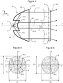
- the figure 3 is an axial sectional view of the optical module of the figure 1 .
- the figure 4 is a diagram representing the projection of the composite light beam generated by the optical system of the figure 2 , before distribution by the optical diffuser, in a plane orthogonal to the optical axis of said system.
- the figure 5 is a diagram representing the projection of the composite light beam generated by the optical system of the figure 2 , after distribution by the optical diffuser, in a plane orthogonal to the optical axis of said system.
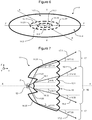
- the figure 6 is a cross-sectional view of an optical system according to the present invention.
- the figure 7 is an axial sectional view of the optical module according to the present invention, equipped with the optical system of the figure 6 .
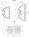
- Diagrams A and B of the figure 8 are two views in axial section of the optical system integrated in the optical module of the figure 6 .
- the figure 9 is a diagram representing the projection of the composite light beam generated by the optical system of the figure 6 , before distribution by the optical diffuser, in a plane orthogonal to the optical axis of said system.
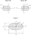
- FIGS. 10A and 10B are diagrams representing the projections of the contributions of the two opposite sides of the optical system of the figure 6 to the composite light beam, after distribution by the optical diffuser, in a plane orthogonal to the optical axis of said system.
- the figure 11 is a diagram representing the projection of the composite light beam generated by the optical system of the figure 6 , after distribution by the optical diffuser, in a plane orthogonal to the optical axis of said system.
- optical systems are shown schematically, regardless of the scales, only with the elements that have a significant optical role (unlike the mounting elements and mechanical adjustment).
- the optical module 1 comprises a light source 2, for example a light-emitting diode (LED) whose emission is Lambertian in a half-space, for example of red color for a stop light.
- This source 2 is associated with a radiator 3A and fixed in known manner on a printed circuit 3B.
- the module 1 also comprises a collimator 4, arranged with respect to the light source 2 so as to generate a composite light beam 6-7 comprising a central light beam 6 and a peripheral light beam 7 surrounding said central light beam 6 contiguously, the light rays of these two beams 6 and 7 being parallel to each other and also parallel to the optical axis XX of said module 1.
- the optical module 1 finally comprises an optical diffuser 5 disposed downstream of the collimator 4 (but it can also be under the form of a contribution of material on the collimator 4) in order to distribute the light of the composite light beam 6-7 according to the regulations applicable to the corresponding lighting and / or signaling light.
- the collimator 4 is shown in more detail on the figure 2 . It is made in a monolithic piece, with symmetry of revolution around the optical axis XX (diagram A of the figure 2 ), whose outline 4.1 to 4.4 (diagram B of the figure 2 ) has a shape capable of generating the central light beam 6 and the peripheral light beam 7.
- the contour of the collimator 4 has a central portion 4.1 and a peripheral portion 4.3 joined to each other at a straight intermediate portion 4.2, substantially parallel to the axis XX optics.
- the contour of the collimator 4 also has a downstream portion 4.4 plane and perpendicular to the optical axis X-X.
- the central portion 4.1 forms with the central portion of the downstream portion 4.4 a convex lens whose focus is located at the source 2, so that the central light beam 6 can be obtained ( figure 3 ) by refraction of the light rays 6.1, 6.2 and 6.3 emitted by the source 2 on the central portion 4.1 of the contour of the collimator 4 and then on the central part of the downstream portion 4.4, these light rays 6.1 to 6.3 then being parallel to the axis XX optics.
- the peripheral portion 4.3 has a substantially parabolic shape, whose axis of symmetry is the optical axis XX and the focus F is located at the source 2, so that the peripheral light beam 7 can be obtained ( figure 3 ) by refraction of the light rays 7.1 and 7.2 emitted by the source 2 on the intermediate portion 4.2, then by total reflection on the surface corresponding to said peripheral portion 4.3 and finally by refraction on the peripheral portion of the downstream portion 4.4, these light rays 7.1 and 7.2 are then also parallel to the optical axis XX (before they pass through the optical diffuser 5).
- the peripheral light beam 7 surrounds the central light beam 6 contiguously.
- the composite light beam thus generated which comprises the central and peripheral light beams 7, is intended to be directed towards the optical diffuser 5 (FIG. figure 3 ), which has the form of a screen whose surface 5.2 facing the collimator 4 is provided with a plurality of microstructures 5.1 and the other surface is flat, so as to produce a lighting which, in a plane (YY ZZ) orthogonal to the optical axis XX of the optical module 1, has certain features related to the regulations in force for lighting and / or signaling lamps for motor vehicles, in particular with regard to uniformity and angular opening.
- the projection of the composite light beam thus generated in a first plane (YY; ZZ) orthogonal to the optical axis XX, before passing through the optical diffuser 5, is represented on the figure 4 .
- This beam is derived from the juxtaposition of the central light beam 6, in the center, and the peripheral light beam 7, around said central light beam 6.
- the dimensions of this projection of the composite beam, along the two axes YY and ZZ orthogonal to each other, are designated by DY 1 and ⁇ Z 1 on the figure 4 .
- FIG. figure 5 which represents the projection of the composite light beam in the first plane (YY; ZZ) orthogonal to the optical axis XX after passing through the optical diffuser 5 and away from this diffuser, which then results in a composite light beam whose angular apertures along the two axes YY and ZZ (to which correspond, on the figure 5 the dimensions ⁇ Y 2 and ⁇ Z 2 of the projection of the beam in said plane (YY-; ZZ) can not reach 45 ° without resorting to a location of the microstructures on the inlet face of a diffuser, which implies while this diffuser is distinct from the collimator.
- the invention proposes replacing the collimator 4 by an optical system 14 capable of generating, not plus a light beam of rays parallel to the optical axis and symmetry of revolution about said optical axis XX, but a beam whose characteristics differ depending on the plane (including the optical axis XX) in which the light rays propagate.
- This optical system 14 is made of a monolithic piece of oblong shape, the major axis of which is arranged for example along the ZZ axis as shown on FIG. figure 6 , unlike the collimator 4 whose shape is circular in this same plane (diagram A of the figure 2 ).
- This optical system 14 is arranged with respect to the light source 12 so as to generate a composite light beam 16-17, comprising a central light beam 16 and a peripheral light beam 17 surrounding said central light beam 16 contiguously.
- the angle of incidence of the light rays on the medium plane containing the diffuser 15 being non-zero, the emerging light rays can be deflected by an angle greater than 45 °, which allows the realization of a reversing light of horizontal angular aperture of the order of 45 °).
- the outline of the monolithic part forming the optical system 14 has different shapes according to the sectional plane thereof.
- the contour of the system 14, represented in the diagram A of FIG. figure 8 is substantially identical to that of the collimator 4 of figures 2 and 3 .
- the contour of the system 14, shown in diagram B of FIG. figure 8 has a shape adapted to the formation of a high angular aperture beam.
- the outline of the optical system 14 has a peripheral portion 14.3 formed of two portions 14.31 and 14.32 of substantially parabolic shape, of greater inclination to the peripheral portion 4.3 of the collimator 4 of the figures 2 and 3 in the cutting plane (XX; YY).
- the outline of the optical system 14 also has a central portion 14.1 formed of two portions 14.11 and 14.12 arranged to deflect the light rays 16.1 and 16.2 with respect to the optical axis X-X, respectively at angles ⁇ 16.1 and ⁇ 16.2.
- the peripheral portion 14.3 and the central portion 14.1 are joined to each other by an intermediate portion 14.2 formed of two portions 14.21 and 14.22 straight and forming with the optical axis XX positive angles ⁇ , so that said portions 14.21 and 14.22 extend along a line that intersects the optical axis at a point D located downstream of the light source (with respect to the direction of propagation of the light rays emitted by said source).
- the central portion 14.1 of the part 14 can be formed by means of a molding tool that can be easily removed.
- the peripheral portion 14.3 is formed of a first substantially parabolic surface portion 14.31, on one side of the optical axis XX, and a second surface portion substantially parabolic 14.32, on the other side of the optical axis XX.
- the foci of these two portions of substantially parabolic surface are merged, so that said substantially parabolic surface portions 14.31 and 14.32 have a common focus F.
- these two portions 14.31 and 14.32 which are respectively disposed on either side of the optical axis XX, are respectively configured so that, when the light source 12 is disposed at the common focus F at said portions, rays such that the light rays 17.1 and 17.2 emitted by said source 12 are respectively inclined with respect to said optical axis XX, at angles ⁇ 17.1 and ⁇ 17.2, after reflection on said portions of parabolic surfaces respectively 14.31 and 14.32.
- the axes BB and CC are, respectively, downstream of the light source 12 (with respect to the direction of propagation of said beam), located on the side of the parabolic surface portion corresponding.
- axis of a substantially parabolic surface portion the axis of symmetry of the corresponding parabolic surface if it is in full and not just a portion thereof.
- the rays 17.1 and 17.2 of the peripheral light beam 17 can be directed adequately ( figure 7 ) by refraction respectively on the portions 14.21 and 14.22, then by total reflection respectively on the portions of substantially parabolic surfaces 14.31 and 14.32 (which are part of the peripheral portion 14.3), these light rays 17.1 and 17.2 respectively being respectively, from other of the optical axis XX, inclined with respect to said optical axis XX at angles ⁇ 17.11 (positive) and ⁇ 17.21 (negative).
- the central light beam 16, meanwhile, can be obtained ( figure 7 ) by refraction of the light rays 16.1 and 16.2 emitted by the source 12 respectively on the portions 14.11 and 14.12, these light rays 16.1 and 16.2 then being divergent and inclined with respect to the optical axis XX at angles ⁇ 16.11 (positive) and ⁇ 16.21 (negative).
- the outline of the system 14 has a set of patterns 15.1 forming the optical diffuser 15.
- the shape of the contour of the system 14 evolves for example continuously and progressively, the shape in the plane (XX; YY) (diagram A of the figure 8 ) to the shape in the plane (XX; ZZ) (diagram B of the figure 8 ), the monolithic piece forming the optical system 14 then having no discontinuity.
- the lighting thus generated may have a distribution in accordance with the regulations in force and a horizontal angular aperture of the order of 45 °, the light rays 16.1, 16.2, 17.1 and 17.2 then being inclined with respect to the optical axis XX respectively angles ⁇ 16.12, ⁇ 16.22, ⁇ 17.12 and ⁇ 17.22 greater than the angles respectively ⁇ 16.11, ⁇ 16.21, ⁇ 17.11 and ⁇ 17.21 of said light rays before passing through the optical diffuser 15.
- the resulting composite light beam 18, resulting from the juxtaposition of these two contributions 18.1 and 18.2, is represented on the figure 11 .
- the angular apertures of this beam, to which the dimensions ⁇ Y 2 and ⁇ Z 2 correspond, can then reach values greater than those obtained by the prior embodiments of a single monolithic component constituting the optical system and the optical diffuser.
- the invention described above represents the case of a divergent peripheral light beam 17, but the invention can also be realized with a convergent peripheral light beam.
- the shape of the peripheral portion 14.3 of the system contour 14 is adapted to generate light rays 17.1 and 17.2 inclined relative to the optical axis with angles ⁇ 17.11 negative and ⁇ 17.21 positive.
- the axes BB and CC of the first portion 14.31 and the second parabolic surface portion 14.32 are, downstream of the light source 12 (with respect to the direction of propagation of the light rays 17.1 and 17.2 emitted by said source 12) respectively on the opposite side of the corresponding parabolic surface portion 14.31 or 14.32.
- each pattern 15.1 of the optical diffuser 15 it is important, in accordance with the invention, for each pattern 15.1 of the optical diffuser 15 to receive a single inclination of light beam.
Landscapes
- Physics & Mathematics (AREA)
- Engineering & Computer Science (AREA)
- Optics & Photonics (AREA)
- General Engineering & Computer Science (AREA)
- General Physics & Mathematics (AREA)
- Microelectronics & Electronic Packaging (AREA)
- Non-Portable Lighting Devices Or Systems Thereof (AREA)
- Instruments For Viewing The Inside Of Hollow Bodies (AREA)
Applications Claiming Priority (1)
| Application Number | Priority Date | Filing Date | Title |
|---|---|---|---|
| FR1152682A FR2973476A1 (fr) | 2011-03-31 | 2011-03-31 | Systeme optique pour generer un faisceau lumineux composite de large ouverture angulaire |
Publications (2)
| Publication Number | Publication Date |
|---|---|
| EP2505909A2 true EP2505909A2 (de) | 2012-10-03 |
| EP2505909A3 EP2505909A3 (de) | 2017-06-28 |
Family
ID=45757346
Family Applications (1)
| Application Number | Title | Priority Date | Filing Date |
|---|---|---|---|
| EP12158119.3A Withdrawn EP2505909A3 (de) | 2011-03-31 | 2012-03-05 | Optisches System zur Erzeugung eines kombinierten Lichtstrahls mit großem Öffnungswinkel |
Country Status (4)
| Country | Link |
|---|---|
| US (1) | US8845142B2 (de) |
| EP (1) | EP2505909A3 (de) |
| JP (1) | JP5976365B2 (de) |
| FR (1) | FR2973476A1 (de) |
Cited By (5)
| Publication number | Priority date | Publication date | Assignee | Title |
|---|---|---|---|---|
| IT201600086947A1 (it) * | 2016-08-24 | 2018-02-24 | Olsa Spa | Dispositivo fanale per funzione retromarcia. |
| WO2018200983A1 (en) * | 2017-04-27 | 2018-11-01 | Lutron Ketra, Llc | Total internal reflection lens having a tapered sidewall entry and a concave spherical exit bounded by a compound parabolic concentrator outer surface to lessen glare while maintaining color mixing and beam control of an led light source |
| US10591134B2 (en) | 2016-01-19 | 2020-03-17 | Lutron Ketra, Llc | Lens for improved color mixing and beam control of an LED light source |
| CN111306508A (zh) * | 2020-03-17 | 2020-06-19 | 马瑞利汽车零部件(芜湖)有限公司 | 一种在相邻准直器的交叉处倒角前位置开孔的厚壁件光学系统 |
| US11106025B2 (en) | 2016-01-19 | 2021-08-31 | Lutron Technology Company Llc | Total internal reflection lens having a straight sidewall entry and a concave spherical exit bounded by a compound parabolic concentrator outer surface to improve color mixing of an LED light source |
Families Citing this family (21)
| Publication number | Priority date | Publication date | Assignee | Title |
|---|---|---|---|---|
| US9164268B2 (en) * | 2009-02-03 | 2015-10-20 | Fraen Corporation | Light mixing optics and systems |
| US10047930B2 (en) * | 2011-12-02 | 2018-08-14 | Seoul Semiconductor Co., Ltd. | Light emitting module and lens |
| EP4242516B1 (de) * | 2011-12-02 | 2026-02-25 | Seoul Semiconductor Co., Ltd. | Lichtemittierendes modul und linse |
| JP6127538B2 (ja) * | 2013-01-25 | 2017-05-17 | 市光工業株式会社 | 車両用灯具 |
| US20250075868A1 (en) * | 2013-01-30 | 2025-03-06 | Cree Lighting Usa Llc | Lighting Devices Having Optical Waveguides for Controlled Light Distribution |
| KR101524914B1 (ko) * | 2013-03-28 | 2015-06-01 | 엘지이노텍 주식회사 | 광확산 소자, 및 이를 갖는 발광소자 어레이 유닛 |
| WO2015004910A1 (ja) | 2013-07-10 | 2015-01-15 | パナソニックIpマネジメント株式会社 | 照明装置およびその照明装置を搭載した自動車 |
| WO2015017930A1 (en) | 2013-08-05 | 2015-02-12 | Dbm Reflex Enterprises Inc. | Injection-molded thick lens |
| US9435515B2 (en) * | 2014-01-31 | 2016-09-06 | Energizer Brands, Llc | Near-field lens with convex hyperbolic surface |
| WO2015129251A1 (ja) * | 2014-02-27 | 2015-09-03 | パナソニックIpマネジメント株式会社 | 照明装置およびその照明装置を搭載した自動車 |
| CN105258074A (zh) * | 2014-07-18 | 2016-01-20 | 欧司朗有限公司 | 一种透镜和包括该透镜的照明装置 |
| TW201629387A (zh) * | 2015-02-12 | 2016-08-16 | 中強光電股份有限公司 | 車燈模組及透鏡 |
| US10393341B2 (en) | 2015-04-24 | 2019-08-27 | Abl Ip Holding Llc | Tri-lobe optic and associated light fixtures |
| USD779112S1 (en) | 2015-04-24 | 2017-02-14 | Abl Ip Holding Llc | Tri-lobe light fixture optic |
| JP6332491B1 (ja) | 2017-02-13 | 2018-05-30 | オムロン株式会社 | レーザ照明装置およびこれを備えた周辺監視センサ |
| US10330902B1 (en) | 2017-06-16 | 2019-06-25 | Dbm Reflex Enterprises Inc. | Illumination optics and devices |
| US10260693B1 (en) * | 2017-12-08 | 2019-04-16 | T.Y.C. Brother Industrial Co., Ltd. | Vehicle lamp lens |
| CN110553213B (zh) * | 2018-06-01 | 2022-01-07 | 深圳市绎立锐光科技开发有限公司 | 光源模组 |
| CN117192796B (zh) * | 2023-10-25 | 2026-02-03 | 江苏弘德光电材料科技有限公司 | 一种准直膜及含其显示模组 |
| US12584609B2 (en) * | 2024-08-30 | 2026-03-24 | Abl Ip Holding Llc | Arrayed optics and light fixtures including the same |
| US12613021B1 (en) | 2025-04-30 | 2026-04-28 | Myotek Holdings, Inc. | Fog lamp with adjustable cut-off line |
Citations (2)
| Publication number | Priority date | Publication date | Assignee | Title |
|---|---|---|---|---|
| FR2919913A1 (fr) | 2007-08-10 | 2009-02-13 | Valeo Vision Sa | Module optique pour dispositif d'eclairage et/ou de signalisation de vehicule |
| EP2230446A1 (de) | 2009-03-17 | 2010-09-22 | Valeo Vision | Beleuchtungs- oder Signalisierungsvorrichtung für ein Kraftfahrzeug |
Family Cites Families (12)
| Publication number | Priority date | Publication date | Assignee | Title |
|---|---|---|---|---|
| US2224178A (en) * | 1940-05-08 | 1940-12-10 | Ralph E Bitner | Catadioptrical lens system |
| JPS59208520A (ja) * | 1983-05-12 | 1984-11-26 | Matsushita Electric Ind Co Ltd | 投光器 |
| DE102004042125B4 (de) * | 2004-08-30 | 2008-05-08 | Schefenacker Vision Systems Germany Gmbh & Co. Kg | Leuchteinheit mit einer Vielzahl gekrümmter Flächenelemente |
| US7461960B2 (en) * | 2006-05-05 | 2008-12-09 | Zweibruder Optoelectronics | LED illumination module |
| US7837349B2 (en) * | 2007-06-15 | 2010-11-23 | Visteon Global Technologies, Inc. | Near field lens |
| JP5279329B2 (ja) * | 2008-04-24 | 2013-09-04 | パナソニック株式会社 | レンズ付発光ユニット |
| TW201011349A (en) * | 2008-09-10 | 2010-03-16 | E Pin Optical Industry Co Ltd | Plano-Fresnel LED lens for angular distribution patterns and LED assembly thereof |
| US8075165B2 (en) * | 2008-10-14 | 2011-12-13 | Ledengin, Inc. | Total internal reflection lens and mechanical retention and locating device |
| JP5254744B2 (ja) * | 2008-10-31 | 2013-08-07 | 株式会社エンプラス | 照明用レンズおよびこれを備えた照明装置 |
| US9164268B2 (en) | 2009-02-03 | 2015-10-20 | Fraen Corporation | Light mixing optics and systems |
| JP4925480B2 (ja) * | 2009-04-17 | 2012-04-25 | パナソニック株式会社 | Ledユニット及び照明器具 |
| DE102009021182A1 (de) * | 2009-05-13 | 2010-11-18 | Hella Kgaa Hueck & Co. | Beleuchtungsvorrichtung für Straßen |
-
2011
- 2011-03-31 FR FR1152682A patent/FR2973476A1/fr active Pending
-
2012
- 2012-03-05 EP EP12158119.3A patent/EP2505909A3/de not_active Withdrawn
- 2012-03-30 JP JP2012079394A patent/JP5976365B2/ja not_active Expired - Fee Related
- 2012-04-02 US US13/437,181 patent/US8845142B2/en not_active Expired - Fee Related
Patent Citations (2)
| Publication number | Priority date | Publication date | Assignee | Title |
|---|---|---|---|---|
| FR2919913A1 (fr) | 2007-08-10 | 2009-02-13 | Valeo Vision Sa | Module optique pour dispositif d'eclairage et/ou de signalisation de vehicule |
| EP2230446A1 (de) | 2009-03-17 | 2010-09-22 | Valeo Vision | Beleuchtungs- oder Signalisierungsvorrichtung für ein Kraftfahrzeug |
Cited By (13)
| Publication number | Priority date | Publication date | Assignee | Title |
|---|---|---|---|---|
| US12234984B2 (en) | 2016-01-19 | 2025-02-25 | Lutron Technology Company Llc | Lens for improved color mixing and beam control of an LED light source |
| US10591134B2 (en) | 2016-01-19 | 2020-03-17 | Lutron Ketra, Llc | Lens for improved color mixing and beam control of an LED light source |
| US11106025B2 (en) | 2016-01-19 | 2021-08-31 | Lutron Technology Company Llc | Total internal reflection lens having a straight sidewall entry and a concave spherical exit bounded by a compound parabolic concentrator outer surface to improve color mixing of an LED light source |
| US11346527B2 (en) | 2016-01-19 | 2022-05-31 | Lutron Technology Company Llc | Lens for improved color mixing and beam control of an LED light source |
| US11681131B2 (en) | 2016-01-19 | 2023-06-20 | Lutron Technology Company Llc | Total internal reflection lens to improve color mixing of an LED light source |
| US11885945B2 (en) | 2016-01-19 | 2024-01-30 | Lutron Technology Company Llc | Total internal reflection lens to improve color mixing of an LED light source |
| US11920780B2 (en) | 2016-01-19 | 2024-03-05 | Lutron Technology Company Llc | Lens for improved color mixing and beam control of an LED light source |
| US12253661B2 (en) | 2016-01-19 | 2025-03-18 | Lutron Technology Company Llc | Total internal reflection lens to improve color mixing of an LED light source |
| US12523352B2 (en) | 2016-01-19 | 2026-01-13 | Lutron Technology Company Llc | Lens for improved color mixing and beam control of an LED light source |
| US12535667B2 (en) | 2016-01-19 | 2026-01-27 | Lutron Technology Company Llc | Total internal reflection lens to improve color mixing of an LED light source |
| IT201600086947A1 (it) * | 2016-08-24 | 2018-02-24 | Olsa Spa | Dispositivo fanale per funzione retromarcia. |
| WO2018200983A1 (en) * | 2017-04-27 | 2018-11-01 | Lutron Ketra, Llc | Total internal reflection lens having a tapered sidewall entry and a concave spherical exit bounded by a compound parabolic concentrator outer surface to lessen glare while maintaining color mixing and beam control of an led light source |
| CN111306508A (zh) * | 2020-03-17 | 2020-06-19 | 马瑞利汽车零部件(芜湖)有限公司 | 一种在相邻准直器的交叉处倒角前位置开孔的厚壁件光学系统 |
Also Published As
| Publication number | Publication date |
|---|---|
| FR2973476A1 (fr) | 2012-10-05 |
| JP2012216542A (ja) | 2012-11-08 |
| JP5976365B2 (ja) | 2016-08-23 |
| US20120250331A1 (en) | 2012-10-04 |
| US8845142B2 (en) | 2014-09-30 |
| EP2505909A3 (de) | 2017-06-28 |
Similar Documents
| Publication | Publication Date | Title |
|---|---|---|
| EP2505909A2 (de) | Optisches System zur Erzeugung eines kombinierten Lichtstrahls mit großem Öffnungswinkel | |
| EP3124854B1 (de) | Beleuchtungssystem für kraftfahrzeugscheinwerfer | |
| EP1746339B1 (de) | Vorrichtung zur Beleuchtung oder Signalgebung, insbesondere für Fahrzeuge | |
| EP1288562B1 (de) | Beleuchtungs- oder Signalvorrichtung für Fahrzeug | |
| EP3167226B1 (de) | Beleuchtungsmodul für ein kraftfahrzeug | |
| EP2743567A1 (de) | Optisches Hauptelement, Beleuchtungsmodul und Scheinwerfer für Kraftfahrzeug | |
| EP2867717B1 (de) | Bestimmungsverfahren einer asphärischen linse und lichtmodul damit für ein kraftfahrzeug | |
| EP2518392A2 (de) | Signalisierungsvorrichtung mit Stop- und Positionsfunktion, die einen Lichtwellenleiter benutzt und einen 3D-Effekt erzeugt | |
| FR3010772A1 (fr) | Dispositif d'emission de lumiere pour projecteur de vehicule automobile | |
| EP2230446A1 (de) | Beleuchtungs- oder Signalisierungsvorrichtung für ein Kraftfahrzeug | |
| WO2017025439A1 (fr) | Dispositif d'eclairage et/ou de signalisation pour vehicule automobile | |
| FR3103535A1 (fr) | Module lumineux imageant un dioptre formant une surface de reflexion totale | |
| EP2976569B1 (de) | Beleuchtungs- und/oder meldemodul für ein kraftfahrzeug | |
| EP2926049B1 (de) | Fahrzeugsignalisierungsvorrichtung mit dreidimensionaler wirkung | |
| EP3453946A1 (de) | Leuchtmodul für kraftfahrzeug, und beleuchtungs- und/oder signalisierungsvorrichtung, die mit einem solchen modul ausgestattet ist | |
| EP3453955B1 (de) | Leuchtmodul zur beleuchtung und/oder signalisierung eines kraftfahrzeugs | |
| FR2919913A1 (fr) | Module optique pour dispositif d'eclairage et/ou de signalisation de vehicule | |
| FR3068110B1 (fr) | Module lumineux a eclairage variable | |
| EP2711618A1 (de) | Beleuchtungsvorrichtung und/oder Signalvorrichtung für Fahrzeug | |
| EP2853804B1 (de) | Beleuchtungs- und/oder signalisierungsmodul mit mehreren drehbaren optischen systemen | |
| EP3454097A1 (de) | Linse zur formgebung von leuchtstrahlen für ein leuchtmodul zur beleuchtung und/oder signalisierung eines kraftfahrzeugs | |
| FR3075924B1 (fr) | Module lumineux a balayage de faisceau lumineux, notamment pour vehicule automobile, muni d’un systeme de focalisation a deux lentilles, et dispositif lumineux de vehicule automobile | |
| FR2918441A1 (fr) | Projecteur de vehicule | |
| FR3077117A1 (fr) | Module lumineux pour vehicule automobile, et dispositif d'eclairage et/ou de signalisation muni d'un tel module | |
| FR3022979A1 (fr) | Systeme d'eclairage et/ou de signalisation pour vehicules automobiles |
Legal Events
| Date | Code | Title | Description |
|---|---|---|---|
| PUAI | Public reference made under article 153(3) epc to a published international application that has entered the european phase |
Free format text: ORIGINAL CODE: 0009012 |
|
| AK | Designated contracting states |
Kind code of ref document: A2 Designated state(s): AL AT BE BG CH CY CZ DE DK EE ES FI FR GB GR HR HU IE IS IT LI LT LU LV MC MK MT NL NO PL PT RO RS SE SI SK SM TR |
|
| AX | Request for extension of the european patent |
Extension state: BA ME |
|
| PUAL | Search report despatched |
Free format text: ORIGINAL CODE: 0009013 |
|
| AK | Designated contracting states |
Kind code of ref document: A3 Designated state(s): AL AT BE BG CH CY CZ DE DK EE ES FI FR GB GR HR HU IE IS IT LI LT LU LV MC MK MT NL NO PL PT RO RS SE SI SK SM TR |
|
| AX | Request for extension of the european patent |
Extension state: BA ME |
|
| RIC1 | Information provided on ipc code assigned before grant |
Ipc: F21S 8/10 20060101AFI20170522BHEP Ipc: F21V 5/00 20150101ALI20170522BHEP Ipc: G02B 17/08 20060101ALI20170522BHEP |
|
| STAA | Information on the status of an ep patent application or granted ep patent |
Free format text: STATUS: THE APPLICATION IS DEEMED TO BE WITHDRAWN |
|
| 18D | Application deemed to be withdrawn |
Effective date: 20180103 |