EP2505943A2 - Appareil de refroidissement doté de tiroirs de refroidissement agencés les uns sur les autres - Google Patents
Appareil de refroidissement doté de tiroirs de refroidissement agencés les uns sur les autres Download PDFInfo
- Publication number
- EP2505943A2 EP2505943A2 EP12161288A EP12161288A EP2505943A2 EP 2505943 A2 EP2505943 A2 EP 2505943A2 EP 12161288 A EP12161288 A EP 12161288A EP 12161288 A EP12161288 A EP 12161288A EP 2505943 A2 EP2505943 A2 EP 2505943A2
- Authority
- EP
- European Patent Office
- Prior art keywords
- drawer
- refrigeration
- compartment
- appliance according
- refrigerating appliance
- Prior art date
- Legal status (The legal status is an assumption and is not a legal conclusion. Google has not performed a legal analysis and makes no representation as to the accuracy of the status listed.)
- Withdrawn
Links
- 238000001816 cooling Methods 0.000 title abstract description 15
- 238000005057 refrigeration Methods 0.000 claims abstract description 130
- 238000009413 insulation Methods 0.000 claims description 11
- 239000003507 refrigerant Substances 0.000 claims description 10
- 239000000284 extract Substances 0.000 claims description 5
- 238000007789 sealing Methods 0.000 claims description 5
- 238000009423 ventilation Methods 0.000 description 23
- 239000003570 air Substances 0.000 description 22
- 239000012080 ambient air Substances 0.000 description 8
- 238000009833 condensation Methods 0.000 description 7
- 230000005494 condensation Effects 0.000 description 7
- 230000015572 biosynthetic process Effects 0.000 description 4
- 238000010276 construction Methods 0.000 description 2
- 230000004308 accommodation Effects 0.000 description 1
- 238000004026 adhesive bonding Methods 0.000 description 1
- 238000011109 contamination Methods 0.000 description 1
- 230000001419 dependent effect Effects 0.000 description 1
- 235000013399 edible fruits Nutrition 0.000 description 1
- 238000005265 energy consumption Methods 0.000 description 1
- 230000002349 favourable effect Effects 0.000 description 1
- 238000003780 insertion Methods 0.000 description 1
- 230000037431 insertion Effects 0.000 description 1
- 238000009434 installation Methods 0.000 description 1
- 238000002955 isolation Methods 0.000 description 1
- 238000004519 manufacturing process Methods 0.000 description 1
- 235000013372 meat Nutrition 0.000 description 1
- 238000012986 modification Methods 0.000 description 1
- 230000004048 modification Effects 0.000 description 1
- 235000019645 odor Nutrition 0.000 description 1
- 239000000565 sealant Substances 0.000 description 1
- 235000013311 vegetables Nutrition 0.000 description 1
Images


Classifications
-
- F—MECHANICAL ENGINEERING; LIGHTING; HEATING; WEAPONS; BLASTING
- F25—REFRIGERATION OR COOLING; COMBINED HEATING AND REFRIGERATION SYSTEMS; HEAT PUMP SYSTEMS; MANUFACTURE OR STORAGE OF ICE; LIQUEFACTION SOLIDIFICATION OF GASES
- F25D—REFRIGERATORS; COLD ROOMS; ICE-BOXES; COOLING OR FREEZING APPARATUS NOT OTHERWISE PROVIDED FOR
- F25D23/00—General constructional features
- F25D23/02—Doors; Covers
- F25D23/021—Sliding doors
-
- F—MECHANICAL ENGINEERING; LIGHTING; HEATING; WEAPONS; BLASTING
- F25—REFRIGERATION OR COOLING; COMBINED HEATING AND REFRIGERATION SYSTEMS; HEAT PUMP SYSTEMS; MANUFACTURE OR STORAGE OF ICE; LIQUEFACTION SOLIDIFICATION OF GASES
- F25D—REFRIGERATORS; COLD ROOMS; ICE-BOXES; COOLING OR FREEZING APPARATUS NOT OTHERWISE PROVIDED FOR
- F25D2323/00—General constructional features not provided for in other groups of this subclass
- F25D2323/002—Details for cooling refrigerating machinery
- F25D2323/0026—Details for cooling refrigerating machinery characterised by the incoming air flow
- F25D2323/00264—Details for cooling refrigerating machinery characterised by the incoming air flow through the front bottom part
-
- F—MECHANICAL ENGINEERING; LIGHTING; HEATING; WEAPONS; BLASTING
- F25—REFRIGERATION OR COOLING; COMBINED HEATING AND REFRIGERATION SYSTEMS; HEAT PUMP SYSTEMS; MANUFACTURE OR STORAGE OF ICE; LIQUEFACTION SOLIDIFICATION OF GASES
- F25D—REFRIGERATORS; COLD ROOMS; ICE-BOXES; COOLING OR FREEZING APPARATUS NOT OTHERWISE PROVIDED FOR
- F25D25/00—Charging, supporting, and discharging the articles to be cooled
- F25D25/02—Charging, supporting, and discharging the articles to be cooled by shelves
- F25D25/024—Slidable shelves
- F25D25/025—Drawers
Definitions
- the invention relates to a refrigeration device with superposed refrigerated drawers.
- Refrigeration appliances with two or more superimposed refrigerated drawers for domestic and commercial use are known from the prior art.
- the refrigerated drawers have an upwardly open shell, which is formed by a rear wall, a front wall opposite the rear wall, two opposing side walls and a bottom connecting all walls.
- the refrigerated drawers are extendable stored in a support structure or a housing of the refrigerator and can be easily managed from above, that is, they can be easily filled from above with refrigerated goods and the refrigerated goods can also be easily removed through the upper opening of the refrigerated drawer again.
- WO 2007/036736 A1 An example of such a refrigeration device is in WO 2007/036736 A1 disclosed. It includes refrigerated drawers with trays whose shell walls - including the bottom of the bowl - are well insulated. The shell walls have upper edges that define the shell opening. Each refrigerated drawer is associated with an insulated lid, which cooperates with the upper edges of the shell walls thermally insulating in the closed state of the refrigerated drawer and closes the refrigerated drawer tightly against the environment. Cover and refrigerated drawer together form a refrigeration unit.
- the refrigeration device comprises a plurality of refrigeration units, which are arranged one above the other in a housing. The lids are firmly anchored in the housing; the refrigerated drawers are mounted extendable below their respective lid in the housing.
- a very similar refrigeration device is in WO 2007 / 010267A2 disclosed. Even with this device, there is an air gap between the refrigeration units. The risk of condensation and the formation of snow in the air gap is counteracted by the fact that the air gap is closed on all sides by seals with closed refrigerated drawer. This improves energy efficiency, since the active circulation of warm air can be dispensed with. In addition, can be dispensed with insulation of the bottom of the upper drawer, whereby usable cooling volume is obtained.
- the air gap is no longer accessible for wet ambient air when the refrigerated drawer is closed, but when opening the drawer, the cold outer surface of the bottom of the refrigerated drawer is still in contact with the warm moist ambient air and brings this at least partially when closing the drawer also in the air gap with.
- WO 2007/010267 A2 can be reduced by the described sealing of the air gap condensation or condensation and ice and snow formation in the air gap, but they can not quite eliminate.
- the trapped air in the air gap can also lead to unpleasant odors.
- Object of the present invention is to provide a refrigeration device with superimposed refrigerated drawers, which shows no condensation and / or ice and snow formation between an upper and a lower refrigeration drawer.
- the refrigerator according to the invention comprises superimposed refrigerated drawers, which are formed open at the top, and a support structure in which the refrigerated drawers are movably mounted between a closed and an open state.
- the refrigeration device comprises a refrigeration compartment, which serves to receive an upper refrigeration drawer and which is closed when closing the upper refrigeration drawer frontally by a front wall of the upper refrigeration drawer, and a lid which is associated with a arranged under the upper refrigeration drawer lower refrigeration drawer and the closed Condition of the lower refrigeration drawer closes it at the top.
- the refrigeration device comprises a stationary in the support structure arranged intermediate bottom, which extends between the two refrigeration drawers and is formed on its underside as a lid for the lower refrigeration drawer and on its upper side as a shelf of the refrigeration compartment for the upper refrigeration drawer. Due to this inventive design of the refrigeration device, the refrigerated drawers can be arranged one above the other without an air gap exists between them, the standing air contained or would be susceptible to condensation / condensation or ice and snow formation. The active circulation of air and especially warm air can be dispensed with, which increases the energy efficiency.
- the intermediate bottom of the refrigeration device is part of the support structure. This simplifies manufacture and reduces assembly time.
- the intermediate bottom of the refrigeration device is a separate component which is anchored in the support structure.
- this can increase the flexibility with respect to the design of the refrigeration device.
- the lower refrigeration drawer can be provided, for example, at different heights of the refrigerating appliance and / or the height of the refrigerating compartment for the upper refrigerating drawer can be varied.
- both embodiments it is advantageous to design the intermediate floor insulated, so that temperature differences between the upper and lower refrigeration drawer remain without consequences and both cold drawers in the closed state with respect to the ambient air are thermally and well shielded and insulated with respect to moisture.
- a cold drawer as Cooling drawer and the other refrigerated drawer form as a freezer drawer, without the temperatures for the individual refrigeration drawers must be continuously readjusted. It is irrelevant whether the upper or the lower refrigeration drawer is designed as a freezer drawer, both is possible.
- both refrigerated drawers as freezer drawers or both refrigerated drawers as refrigerated drawers with deliberately different temperatures for different frozen goods or refrigerated goods (finished products, fruit / vegetables, meat).
- the upper refrigeration drawer is advantageously stored in a refrigeration compartment, wherein the refrigeration compartment has a compartment opening at the front, bounded by compartment walls which together with their free end sides form a frame around the compartment opening.
- the frame cooperates with an insulated front wall of the upper refrigerating drawer in such a way that the refrigerating compartment in which the upper refrigerating drawer is stored is thermally sealed.
- a thermal seal is provided between the frame of the compartment opening and the front wall of the refrigerated drawer.
- the seal is fixed on the frame.
- the seal is better protected against damage when operating the refrigerated drawer.
- the seal is fixed on an inner side of the insulated front wall of the upper refrigeration drawer. Regardless of where the seal is attached, it can be glued or incorporated, for example, in a designated groove.
- the sealing plane between the refrigerating compartment and the upper refrigerating drawer is oriented more or less vertically independently of the individual configuration in this embodiment.
- the upper refrigeration drawer advantageously has a shell, the shell walls and the shell bottom are uninsulated and which is firmly connected to the insulated front wall of the refrigerated drawer.
- the shell may for example be hung in the front wall of the drawer or glued to it; it may be screwed on or fastened to the front wall with the aid of a snap connection, this listing not being exhaustive, but only a few possible examples shows.
- connection connecting members may be provided on the front wall and / or on the shell. They may be designed such that they allow a desired positioning of the shell with respect to height and possibly also with respect to lateral adjustment.
- the shell walls and possibly also the shell bottom are not insulated and configured either as a closed thin walls or as a basket-like openwork walls.
- the lower refrigeration drawer is insulated on all sides.
- Such configured refrigeration device has a high energy efficiency, since no temperature equalization between environment and content of the refrigerated drawer can take place on the isolated walls of the refrigerated drawer. For this reason, in such an embodiment of the refrigeration appliance according to the invention, those parts of the support structure which laterally surround the lower refrigeration drawer can be designed without insulation. If the bottom of the lower refrigerating drawer is also insulated, then the bottom of the supporting structure can also be designed with little or no insulation, or the supporting structure can be designed without any bottom. All these measures save volume, which is available to the consumer in this way as a usable cooling volume.
- seal is provided between the lid and the lower refrigeration drawer.
- the seal can be provided both on the refrigerated drawer and on the lid or on both.
- the lid of the lower refrigeration drawer has a lower edge, hereinafter referred to as the lower edge
- the lower refrigeration drawer has an upper edge, hereinafter referred to as the upper edge, which is formed by free end faces of those walls which the upper opening of Limit open top of cold drawer.
- the lower edge of the lid and the upper edge of the lower refrigeration drawer are designed such that they cooperate when closing the lower refrigeration drawer and close thermally tight.
- the plane of extension is understood to mean the plane along which the lower refrigerating drawer is moved during opening and closing. If the lower edges of the lid and the upper edges of the lower refrigeration drawer run in a more or less horizontal plane or in a plane which is more or less parallel to the plane of extension, this is very favorable in terms of energy efficiency. When the lower cold drawer is pulled out, hardly any ambient air can then penetrate into the region of the support structure belonging to the lower cold drawer.
- the lower edge of the lid extends obliquely from the front top to the rear bottom, wherein the upper edge of the associated lower refrigeration drawer at the same angle is inclined, so that the edges of the lid and refrigerated drawer engage wedge-shaped when closing and close thermally tight.
- the appreciable resistance which otherwise when moving the cold drawer through the adjacent edges of the lid and drawer or the friction of the seal on the opposite edge or the opposite cooperating with this seal, on the first moment of opening or the last moment to be reduced. This results in an easier mobility of the lower refrigeration drawer and a more comfortable handling for the user.
- the lower refrigeration drawer is advantageously provided with its lower side upper edge lying with an inner container having a horizontally extending upper edge of the container. This ensures that even in the back of the refrigerated drawer stored refrigerated goods can not fall beyond lower upper edge of the refrigerated drawer. The volume of the drawer is fully usable in this way without danger.
- a seal is provided between the upper edge of the lower refrigeration drawer and the lower edge of the lid. This can either be fixed to the upper edge of the drawer or the lower edge of the lid, for example by gluing, insertion into a groove provided for this purpose, screwing a groove strip into which the seal is or will be introduced etc. Seals can also be provided on both edges be, which cooperate sealingly when closing.
- the lower refrigeration drawer is arranged adjacent to the base space.
- the support structure can advantageously be designed without a bottom, so that it is possible to benefit from circulating air in the base space and / or from warm exhaust air from units arranged in the base space.
- the base space is a common place for the accommodation of necessary for the operation of the refrigerator units.
- the refrigeration device is configured such that, in the closed state, part of the lower refrigeration drawer is located in the base space. This increases the usable volume for the user of the refrigerated drawer.
- a ventilation grille extendable connected to the refrigerated drawer.
- FIG. 1 a refrigeration device 10 is shown with a support structure 22 in which two refrigeration drawers 11, 13 are arranged one above the other.
- the refrigerated drawers 11, 13 are movably mounted on extensions 7 between a closed state (shown here) and an open state (not shown) in the support structure 22.
- the extracts 7 are indicated by dashed lines.
- the refrigeration device 10 includes a refrigerating compartment 50 for receiving the upper refrigerating drawer 11, the two superimposed refrigerating drawers 11, 13 and a stationary intermediate floor 44.
- the intermediate bottom 44 is located between the two refrigerated drawers 11, 13 and in this example is part of the support structure 22.
- the intermediate bottom 44 is insulated and formed on its upper side as a shelf 52 of the refrigeration compartment 50.
- the intermediate bottom 44 is formed as a lid 46 which closes the lower refrigerant drawer 13 from above.
- the refrigeration compartment 50 for the upper refrigeration drawer 11 comprises a compartment ceiling 54 opposite the compartment floor 52, a compartment rear wall 58 and two opposite compartment side walls 56. Of the compartment side walls 56, only the rear one can be seen in this illustration.
- the shelf 52, the side walls 56 and the compartment cover 54 each have a free end face, which is aligned against a front side 20 of the refrigerator 10 and together form a frame 60 to a compartment opening 62 through which the upper refrigeration drawer 11 in the refrigeration compartment 50th is introduced.
- the frame 60 cooperates with the upper refrigerated drawer 11 closed with an insulated front wall 64 of the upper refrigerating drawer 11 such that the compartment opening 62 is thermally sealed.
- a seal 68 is provided between frame 60 and front wall 64.
- the seal 68 is mounted on the front side of the frame 60.
- the sealing plane formed by the seal 68 extends in principle vertically. In principle, in this case means that there may be deviations due to tolerances or due to a particular embodiment of the interface between front wall 64 and frame 60 (for example with a step or bevel).
- the walls 52, 54, 56, 58 of the refrigerating compartment 50 are thermally insulated in this embodiment.
- the extracts 7, over which the upper refrigeration drawer 11 is slidably mounted, are arranged on the inside of the compartment side walls 56.
- the upper cold drawer 11 For storage of refrigerated goods, the upper cold drawer 11 is provided with a shell 66 whose shell walls and the bottom of the shell are not insulated, resulting in a larger usable cooling volume and 50 is not necessary due to the good insulation of the refrigeration compartment.
- the shell walls are designed like a basket.
- the shell 66 is fixedly connected to the front wall 64 and designed in this embodiment as a separate component which is hooked via a snap connection in the front wall 64.
- the result of the construction described here is that the uninsulated shell 66 of the upper refrigeration drawer 11 is stored behind the thermally insulated front wall 64 of the refrigerated drawer 11 in a cold compartment 50 thermally insulated against the outside.
- the lower refrigeration drawer 13 has an insulated bottom 90, an insulated front 92, an insulated rear 94 and insulated sidewalls 96, of which latter only the rear one can be seen in this illustration.
- the front side 92, the rear wall 94 and the side walls 96 have upwardly directed free end faces which together form an upper edge 98 of the lower refrigerant drawer 13 and laterally delimit an upper opening 99 of the lower refrigeration drawer 13.
- the upper opening 99 of the likewise insulated lid 46 which is part of the intermediate bottom 44, thermally sealed from above.
- a seal 48 is provided between the cover 46 and the upper edge 98 of the lower refrigeration drawer 13, which is fixed in this example at the upper edge 98 of the refrigerated drawer 13. Due to the good insulation of the lower refrigeration drawer, the support structure is only slightly or not insulated in that region 24 in which it laterally surrounds the lower refrigeration drawer 13. In the example shown here, it also has no bottom.
- the support structure 22 is covered with a worktop 3 and supported on a base 12 which defines a socket space 14 with a base height Hs.
- the refrigeration device 10 comprises an appliance front 20, which is covered with front panels 5.
- the front panels 5 protrude on all sides beyond the front elements 92, 64 of the drawers 11, 13 and obscure insulation and parts of the support structure 22, so that the observer a pleasing sight of the front side 20 of the refrigerator 10 results.
- the base 12 comprises at the front a plinth panel 16 with a ventilation grille 42, which is arranged offset from the front of the device 20, whereby a base recess 30 is defined with the depth T1.
- the ventilation grille 42 is placed in a ventilation duct 40, which serves to ventilate the base space.
- the ventilation grille 42 protects the base space 14 against contamination.
- the lower refrigeration drawer 13 is with its flat bottom 90 so on the extracts 7 in the Supported structure 22 that it can be easily moved over the base panel 16 with its ventilation grille 42 away.
- the base 12 is not part of the refrigeration device 10 in this embodiment, but a separate component that belongs for example to a fitted kitchen (not shown), in which the refrigerator is fitted. Likewise, the front panels 5 are tuned to the appearance of other built-in elements of the kitchen.
- FIG. 2 shows a second embodiment of the refrigerator 10 according to the invention in an analogous sectional view FIG. 1 ,
- the refrigeration device 10 shown essentially corresponds to that FIG. 1 ,
- the refrigeration appliance 10 comprises an appliance front 20, which, as customary in fitted kitchens, is covered with a furniture front 5.
- the furniture front 5 protrudes down beyond the front of the device 20.
- the base 12 comprises at the front a plinth panel 16, which is arranged set back relative to the front panel 20 and whose upper edge 18 is at a lower height than the base height Hs. In this way, the base panel 16 and front panel 20 form a recess 30 with a depth T1.
- This embodiment is different from that FIG. 1 in that the intermediate bottom 44 is a separate component, which is anchored in the support structure 22 in a stationary manner, this being possible in this embodiment at different heights in the support structure 22.
- This design increases the flexibility with respect to the design of the refrigeration device 10, for example, in the same support structure 22 upper refrigeration drawers 11 can be introduced with different heights and / or the lower refrigeration drawer 13 may be provided at different heights in the support structure 22. Also for the lower refrigeration drawer 13 different heights can be provided in this way without major structural measures.
- the intermediate bottom 44 is in turn well insulated and acts against the top as a shelf 52 for the refrigeration compartment 50 of the upper refrigeration drawer 11 and down as a lid 46 relative to the lower refrigeration drawer 13.
- the provided between the lid 46 and the upper edge 98 of the lower refrigeration drawer 13 seal 48th is fixed in this example on the cover 46, whereby the seal is well protected from damage.
- the seal 68 between the frame 60 and the front wall 64 is attached to the inside of the front wall 64 in this example.
- the base 12 is part of the refrigeration device 10 and in the base space 14, the units are housed for the operation of the refrigerator. This increases the usable volume.
- the ventilation duct 40 is not provided here with a ventilation grille.
- the base 12 does not belong to the refrigerator (unlike in FIG. 1 ), it can of course still be used to accommodate 14 base units of the refrigerator in the base space and so to optimize the usable volume of the device.
- FIG. 3 shows in analogous representation to the FIGS. 1 and 2 a third embodiment of the refrigeration device 10 according to the invention, that of FIG. 1 is similar again.
- the intermediate bottom 44 is in turn part of the support structure 22 and forms against the top of the shelf 52 for the refrigeration compartment 50 of the upper refrigeration drawer 11 and against the bottom lid 46 for closing the lower refrigerant drawer 13.
- FIG. 1 extends the upper edge 98 of the lower refrigeration drawer 13 in this embodiment obliquely from the top to the bottom rear, so that the upper edge of the back 94 is lower than the upper edge of the front side 92 of the lower refrigeration drawer 13.
- the lid 46 is fittingly with an equal angle provided obliquely extending lower edge, so that the oblique edges 72 of the refrigerated drawer 13 and lid 46 engage in a wedge shape when closing the lower refrigeration drawer.
- a sealing means 48 is provided between the upper edge 98 of the cold drawer 13 and the lower edge 72 of the lid 46, which ensures a secure seal against the ambient air in the closed state of the lower refrigerant drawer 13. For the tightness, it does not matter whether the sealant 48 is attached to the lower edge 72 of the lid 46 or the upper edge 98 of the cold drawer 13. An attachment to the lower edge 72 of the lid 46, however, reduces the risk of damaging the seal 48 when operating the refrigerated drawer 13.
- FIG. 4 is a section similar to the previously described figures, a fourth embodiment of the refrigerator 10 according to the invention shown, the similar is constructed, like that one out FIG. 3 ,
- the lower refrigeration drawer 13 is additionally provided with an inner container 76 which has a horizontally extending upper edge of the container.
- the inner container 76 is about the same height or slightly lower than the upper edge 98 of the lower refrigeration drawer 13.
- Rear of the inner container 76 is significantly higher than the back, lower upper edge 98 of the lower refrigeration drawer 13.
- FIG. 5 Analogously illustrated fifth embodiment of the refrigeration device 10 is also constructed similar to that of FIG. 3 ,
- the construction of the base 12 and the lower refrigeration drawer 13 and the height of the support of the lower refrigeration drawer 13 by means of the extracts (not explicitly shown here) in the support structure 22 are selected so that the lower refrigerant drawer 13 protrudes with a part 25 in the base space 14 ,
- the front base panel 16 is formed so that its upper edge 18 is at a lower level than the base height Hs.
- the base panel 16 is set back relative to the front panel 20 and defines together with this a base recess 30 with a depth T1.
- the cold drawer 13 has in its front lower portion 21 a recess 32 with a recess bottom 34 and a scrubsprungstirnwand 38, which connects the recess bottom with a lower-lying bottom bottom 28 of the bottom 26/90 located in the base space 14 part 25 of the cold drawer 13.
- the recess 32 of the lower cold drawer 13 follows in its geometry the base recess 30.
- the recess 32 has a greater depth T2 than the recess 30 with depth T1.
- the return bottom 34 traverses the top edge 18 of the base panel 16 at a distance A when the cold drawer 24 is closed. In this embodiment, this distance A defines the height of the air opening 40 between the base edge 18 and recess bottom 34, which is not included in this example a ventilation grille 42 is provided.
- the ventilation of the base space 14 is used for ventilation and cooling housed in the base space 14 units of the refrigerator 10, which are not shown here for simplicity.
- the bottom bottom side 28 of the base in the base space 26 located in the base space 14 part 25 of the lower refrigeration drawer 13 is at least as much higher than the upper edge 18 of the base panel 16 that it can be moved over a movement of the refrigerated drawer 24 over this.
- the part 25 of the refrigerated drawer 24 located in the base space 14 can, as shown here, for the most part be insulation of the floor 26 or, at a smaller insulation thickness, also comprise the cooling volume available to the user.
- the user of the refrigeration device 10 is at least the volume that is above the base portion 14 and was taken in the prior art by the isolation of the bottom 26, now made available as a usable cooling volume.
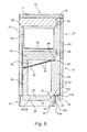
- FIG. 6 illustrated sixth embodiment corresponds to that of FIG. 5 , except that here the intermediate bottom 44 is formed as a separate component, which is the for FIG. 2 described benefits.
- a ventilation grille 42 by means of a mounting member 41 a and fasteners 41 b attached such that it is positioned with some play on the upper edge 18 of the base panel 16.
- the mounting member 41 a may be formed for accurate positioning, for example, as an angle plate with slots and the fasteners 41 b accordingly as clamping screws.
- the ventilation grille 42 also has a stop 43b formed by the grid 42 and a lower grid flange 43a projecting downwardly from the grid.
- the stop 43a is brought into abutment on the one hand with the upper edge 18 of the base panel 16 and the lower mesh flange 43b with its front side during assembly.
- the mounting member 41 a is then fixed by means of the fastening elements 41 b on the ventilation grille 42 and fixed to the lower refrigerant drawer 13. Any gaps that may occur between the ventilation grille 42 and the base panel are cleanly covered by the lower grid flange 43a.
- FIGS. 1 to 4 are each shown to be provided with a lower refrigerant drawer 13, which projects with a part 25 in the base region 14.
- these drawers can be provided with ventilation grill 42.
- the ventilation grille 42 described above may be provided as a separate component or formed on the lower refrigerant drawer 13.
- the ventilation grille 42 may also have a lower grid flange and / or stop.
- the intermediate bottom 44 may be an integral part of the support structure 22 or a separate component.
- the intermediate bottom 44 can be fixed as a separate component either at different heights in the support structure or assigned to a specific height.
- the support structure 22 may be an independent element.
- the support structure may for example also be formed by side walls of other installation elements of a fitted kitchen, which are placed adjacent to the refrigeration device 10.
Landscapes
- Engineering & Computer Science (AREA)
- Chemical & Material Sciences (AREA)
- Combustion & Propulsion (AREA)
- Physics & Mathematics (AREA)
- Mechanical Engineering (AREA)
- Thermal Sciences (AREA)
- General Engineering & Computer Science (AREA)
- Devices That Are Associated With Refrigeration Equipment (AREA)
Applications Claiming Priority (1)
| Application Number | Priority Date | Filing Date | Title |
|---|---|---|---|
| DE102011006605A DE102011006605A1 (de) | 2011-03-31 | 2011-03-31 | Kältegerät mit übereinander angeordneten Kälteschubladen |
Publications (2)
| Publication Number | Publication Date |
|---|---|
| EP2505943A2 true EP2505943A2 (fr) | 2012-10-03 |
| EP2505943A3 EP2505943A3 (fr) | 2017-11-29 |
Family
ID=45932195
Family Applications (1)
| Application Number | Title | Priority Date | Filing Date |
|---|---|---|---|
| EP12161288.1A Withdrawn EP2505943A3 (fr) | 2011-03-31 | 2012-03-26 | Appareil de refroidissement doté de tiroirs de refroidissement agencés les uns sur les autres |
Country Status (2)
| Country | Link |
|---|---|
| EP (1) | EP2505943A3 (fr) |
| DE (1) | DE102011006605A1 (fr) |
Citations (2)
| Publication number | Priority date | Publication date | Assignee | Title |
|---|---|---|---|---|
| WO2007010267A2 (fr) | 2005-07-20 | 2007-01-25 | Applied Design & Engineering Ltd | Ameliorations apportees a une chambre frigorifique |
| WO2007036736A1 (fr) | 2005-09-29 | 2007-04-05 | Applied Design And Engineering Ltd | Unites de vente au detail refrigerees |
Family Cites Families (4)
| Publication number | Priority date | Publication date | Assignee | Title |
|---|---|---|---|---|
| US2145892A (en) * | 1935-10-14 | 1939-02-07 | Rubatex Products Inc | Refrigerator |
| ATE423950T1 (de) * | 2001-03-13 | 2009-03-15 | Applied Design & Eng Ltd | Verwendung von wärme in kühllagervorrichtungen |
| DE102005045328A1 (de) * | 2005-09-22 | 2007-03-29 | BSH Bosch und Siemens Hausgeräte GmbH | Kältegerät mit Bodenmulde |
| DE102007062004A1 (de) * | 2007-12-21 | 2009-06-25 | BSH Bosch und Siemens Hausgeräte GmbH | Kältegerät |
-
2011
- 2011-03-31 DE DE102011006605A patent/DE102011006605A1/de not_active Withdrawn
-
2012
- 2012-03-26 EP EP12161288.1A patent/EP2505943A3/fr not_active Withdrawn
Patent Citations (2)
| Publication number | Priority date | Publication date | Assignee | Title |
|---|---|---|---|---|
| WO2007010267A2 (fr) | 2005-07-20 | 2007-01-25 | Applied Design & Engineering Ltd | Ameliorations apportees a une chambre frigorifique |
| WO2007036736A1 (fr) | 2005-09-29 | 2007-04-05 | Applied Design And Engineering Ltd | Unites de vente au detail refrigerees |
Also Published As
| Publication number | Publication date |
|---|---|
| EP2505943A3 (fr) | 2017-11-29 |
| DE102011006605A1 (de) | 2012-10-04 |
Similar Documents
| Publication | Publication Date | Title |
|---|---|---|
| EP2414756B1 (fr) | Appareil frigorifique ménager | |
| DE102012223538A1 (de) | Wandung für ein Haushaltskältegerät mit einem einstückigen Trägerrahmen für einen Isolationskörper sowie Haushaltskältegerät | |
| WO2005093338A2 (fr) | Appareil de refrigeration comportant deux compartiments de stockage | |
| EP3201546A1 (fr) | Appareil réfrigérant à tiroir | |
| EP2561292A2 (fr) | Vantail de porte, procédé de fabrication d'un vantail de porte et appareil frigorifique équipé d'un vantail de porte | |
| WO2006120073A1 (fr) | Appareil frigorifique pourvu d'un bac a aliments refrigeres guide par des coulisses | |
| EP2318789A1 (fr) | Réfrigérateur avec appareil à glaçons | |
| EP1882140A1 (fr) | Contenant interne d'un appareil refrigerant | |
| EP2606295B1 (fr) | Un refrigerateur avec un rail de support pour une etagère | |
| DE102015206860A1 (de) | Haushaltskältegerät mit entnehmbarer Trennwand in einer Lebensmittelaufnahme-Schale | |
| DE102011006605A1 (de) | Kältegerät mit übereinander angeordneten Kälteschubladen | |
| DE202006003964U1 (de) | Möbel zur Aufnahme von Lebensmitteln und/oder hygienekritischen Gütern | |
| EP1783446B1 (fr) | Réfrigérateur à plancher en forme de cuvette | |
| DE102008063391A1 (de) | Kältegerät mit Fachboden | |
| EP2419687B1 (fr) | Appareil frigorifique sans givre | |
| WO2009000737A2 (fr) | Appareil frigorifique | |
| EP3163229B1 (fr) | Appareil ménager frigorifique comprenant un tiroir supplémentaire personnalisé et procédé de formation d'un tiroir individuel | |
| DE102011006960A1 (de) | Kältegeräteanordnung mit Kältespeicherkörper | |
| DE102013203724A1 (de) | Kältegerät mit einem Zusatznutzraum | |
| DE102012223545A1 (de) | Wandung für ein Haushaltskältegerät mit einem viereckigen Trägerrahmen für einen thermischen Isolationskörper sowie Haushaltskältegerät | |
| DE10063691B4 (de) | Kühlgerät | |
| DE102009026665A1 (de) | Kältegerät | |
| WO2011051126A2 (fr) | Module pour appareil frigorifique | |
| DE10339928A1 (de) | Kältegerät mit Schubladen | |
| DE102008013556A1 (de) | Kältegerät mit einem verschiebbaren Deckel |
Legal Events
| Date | Code | Title | Description |
|---|---|---|---|
| PUAI | Public reference made under article 153(3) epc to a published international application that has entered the european phase |
Free format text: ORIGINAL CODE: 0009012 |
|
| AK | Designated contracting states |
Kind code of ref document: A2 Designated state(s): AL AT BE BG CH CY CZ DE DK EE ES FI FR GB GR HR HU IE IS IT LI LT LU LV MC MK MT NL NO PL PT RO RS SE SI SK SM TR |
|
| AX | Request for extension of the european patent |
Extension state: BA ME |
|
| RAP1 | Party data changed (applicant data changed or rights of an application transferred) |
Owner name: BSH HAUSGERAETE GMBH |
|
| PUAL | Search report despatched |
Free format text: ORIGINAL CODE: 0009013 |
|
| AK | Designated contracting states |
Kind code of ref document: A3 Designated state(s): AL AT BE BG CH CY CZ DE DK EE ES FI FR GB GR HR HU IE IS IT LI LT LU LV MC MK MT NL NO PL PT RO RS SE SI SK SM TR |
|
| AX | Request for extension of the european patent |
Extension state: BA ME |
|
| RIC1 | Information provided on ipc code assigned before grant |
Ipc: F25D 23/02 20060101AFI20171026BHEP |
|
| STAA | Information on the status of an ep patent application or granted ep patent |
Free format text: STATUS: THE APPLICATION IS DEEMED TO BE WITHDRAWN |
|
| 18D | Application deemed to be withdrawn |
Effective date: 20180530 |