EP2506085A2 - Unité photosensible et appareil de formation d'images - Google Patents
Unité photosensible et appareil de formation d'images Download PDFInfo
- Publication number
- EP2506085A2 EP2506085A2 EP12151663A EP12151663A EP2506085A2 EP 2506085 A2 EP2506085 A2 EP 2506085A2 EP 12151663 A EP12151663 A EP 12151663A EP 12151663 A EP12151663 A EP 12151663A EP 2506085 A2 EP2506085 A2 EP 2506085A2
- Authority
- EP
- European Patent Office
- Prior art keywords
- pair
- metal plates
- protrusion
- prescribed direction
- photosensitive unit
- Prior art date
- Legal status (The legal status is an assumption and is not a legal conclusion. Google has not performed a legal analysis and makes no representation as to the accuracy of the status listed.)
- Granted
Links
Images




Classifications
-
- G—PHYSICS
- G03—PHOTOGRAPHY; CINEMATOGRAPHY; ANALOGOUS TECHNIQUES USING WAVES OTHER THAN OPTICAL WAVES; ELECTROGRAPHY; HOLOGRAPHY
- G03G—ELECTROGRAPHY; ELECTROPHOTOGRAPHY; MAGNETOGRAPHY
- G03G21/00—Arrangements not provided for by groups G03G13/00 - G03G19/00, e.g. cleaning, elimination of residual charge
- G03G21/16—Mechanical means for facilitating the maintenance of the apparatus, e.g. modular arrangements
- G03G21/1604—Arrangement or disposition of the entire apparatus
- G03G21/1619—Frame structures
-
- G—PHYSICS
- G03—PHOTOGRAPHY; CINEMATOGRAPHY; ANALOGOUS TECHNIQUES USING WAVES OTHER THAN OPTICAL WAVES; ELECTROGRAPHY; HOLOGRAPHY
- G03G—ELECTROGRAPHY; ELECTROPHOTOGRAPHY; MAGNETOGRAPHY
- G03G21/00—Arrangements not provided for by groups G03G13/00 - G03G19/00, e.g. cleaning, elimination of residual charge
- G03G21/16—Mechanical means for facilitating the maintenance of the apparatus, e.g. modular arrangements
- G03G21/1661—Mechanical means for facilitating the maintenance of the apparatus, e.g. modular arrangements means for handling parts of the apparatus in the apparatus
- G03G21/1671—Mechanical means for facilitating the maintenance of the apparatus, e.g. modular arrangements means for handling parts of the apparatus in the apparatus for the photosensitive element
-
- G—PHYSICS
- G03—PHOTOGRAPHY; CINEMATOGRAPHY; ANALOGOUS TECHNIQUES USING WAVES OTHER THAN OPTICAL WAVES; ELECTROGRAPHY; HOLOGRAPHY
- G03G—ELECTROGRAPHY; ELECTROPHOTOGRAPHY; MAGNETOGRAPHY
- G03G2221/00—Processes not provided for by group G03G2215/00, e.g. cleaning or residual charge elimination
- G03G2221/16—Mechanical means for facilitating the maintenance of the apparatus, e.g. modular arrangements and complete machine concepts
- G03G2221/1651—Mechanical means for facilitating the maintenance of the apparatus, e.g. modular arrangements and complete machine concepts for connecting the different parts
- G03G2221/1654—Locks and means for positioning or alignment
-
- G—PHYSICS
- G03—PHOTOGRAPHY; CINEMATOGRAPHY; ANALOGOUS TECHNIQUES USING WAVES OTHER THAN OPTICAL WAVES; ELECTROGRAPHY; HOLOGRAPHY
- G03G—ELECTROGRAPHY; ELECTROPHOTOGRAPHY; MAGNETOGRAPHY
- G03G2221/00—Processes not provided for by group G03G2215/00, e.g. cleaning or residual charge elimination
- G03G2221/16—Mechanical means for facilitating the maintenance of the apparatus, e.g. modular arrangements and complete machine concepts
- G03G2221/1678—Frame structures
- G03G2221/1684—Frame structures using extractable subframes, e.g. on rails or hinges
Definitions
- the present invention relates to a photosensitive unit supporting a plurality of photosensitive drums and an image forming apparatus provided with the photosensitive unit.
- a tandem type color printer conventionally well known in the art includes a main frame and a photosensitive unit.
- the photosensitive unit integrally supports a plurality of photosensitive drums and is configured to be slidably movable with respect to the main frame.
- the photosensitive unit in the art includes a pair of metal plates, a positioning shaft, and a pair of resin frames.
- the pair of metal plates is adapted for supporting the plurality of photosensitive drums at its axial ends so that the plurality of photosensitive drums is disposed between the pair of metal plates.
- Each of the pair of metal plates has a front end portion (an end portion positioned downstream of another end portion in a mounting direction) formed with a notched portion.
- the positioning shaft extends in a leftward/rightward direction and bridges between rear end portions of the pair of metal plates.
- the pair of resin frames is adapted for supporting the front and rear end portions of the pair of metal plates.
- the main frame is provided with a pressure member and a reference shaft extending in the leftward/rightward direction.
- the pressure member provided in the main frame presses the positioning shaft rearward, so that the notched portions formed in the front end portions of the pair of metal frames are brought into abutment with the reference shaft provided in the main frame.
- the photosensitive unit is positioned with respect to the main frame.
- the positioning shaft needs to be provided in the photosensitive unit for positioning the photosensitive unit in the main frame. This leads to a problem of cost increases.
- the present invention provides a photosensitive unit configured to be mounted in a main frame of an image forming apparatus along a prescribed direction.
- the image forming apparatus includes a pressure unit, a first positioning portion, and a second positioning portion.
- the photosensitive unit includes a plurality of photosensitive drums, a pair of metal plates, and a resin frame.
- the plurality of photosensitive drums is juxtaposedly arrayed with each other in the prescribed direction.
- Each photosensitive drum has an axis extending in an axial direction.
- the pair of metal plates is spaced away from each other in the axial direction and supports the plurality of photosensitive drums.
- the pair of metal plates is configured to be positioned on the second positioning portion.
- the resin frame supports the pair of metal plates and is configured to support a plurality of developer cartridges.
- the resin frame is configured to be positioned on the first positioning portion.
- the pair of metal plates is pressed against the second positioning portion to be positioned with respect to the main frame when the resin frame is pressed by the pressure unit in the prescribed direction.
- the present invention provides an image forming apparatus including a main frame, the above photosensitive unit, a first positioning portion, a second positioning portion, and a pressure unit.
- the first positioning portion and the second positioning portion are disposed in the main frame. Both ends of the photosensitive unit in the prescribed direction are positioned on the first positioning portion and the second positioning portion, respectively.
- the pressure unit is configured to press the photosensitive unit in the prescribed direction.
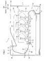
- Fig. 1 is a schematic cross-sectional view of a color printer according to one embodiment of the present invention
- Fig. 2 is a perspective view of a photosensitive unit according to the embodiment
- Fig. 3 is a perspective view of the photosensitive unit from which developing cartridges have been removed;
- Fig. 4 is a perspective view of a resin frame according to the embodiment.
- Fig. 5 is a perspective view of a pair of metal plates supporting a plurality of photosensitive drums according to the embodiment
- Fig. 6 is a perspective view of a pair of side plates and a positioning shaft according to the embodiment
- Fig. 7 is a perspective view of the pair of side plates on which the photosensitive unit is mounted;
- Fig. 8 is a cross-sectional view of a pressure member according to the embodiment.
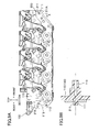
- Fig. 9A is an inner side view of the resin frame and the metal plate before the photosensitive unit is mounted on a main frame of the color printer;
- Fig. 9B is a cross-sectional view of the resin frame and the meal plate taken along a line X-X in Fig. 9A ;
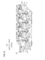
- Fig. 10 is the inner side view of the resin frame and the metal plate after the photosensitive unit is mounted on the main frame and a front cover provided in the main frame is closed;
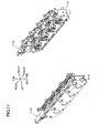
- Fig. 11 is a perspective view of a pair of resin frames according to a first modification of the present invention.
- Fig. 12 is a perspective view of an assembly movable in a frontward/rearward direction relative to the pair of resin frames shown in Fig. 11 ;
- Fig. 13 is a left side view of a pressure member according to the first modification of the present invention, wherein a front cover is opened;
- Fig. 14 is the left side view of the pressure member according to the first modification of the present invention, wherein the front cover is closed;
- Fig. 15 is an inner side view of a resin frame and a metal plate, the metal plate being formed with a pressing hole according to a second modification of the present invention.
- the color printer 1 includes a main frame 10. Within the main frame 10, a sheet supply unit 20, an image forming unit 30, and a discharge unit 90 are provided.
- a left side and a right side are a rear side and a front side, respectively, and a far side and a near side are a right side and a left side, respectively.
- the main frame 10 is formed with an opening 10A.
- a front cover 11 is provided on a front wall of the main frame 10 over the opening 10A.
- the front cover 11 can be pivoted about its bottom edge between a closed position covering the opening 10A and an open position exposing the opening 10A.
- the sheet supply unit 20 serves to supply a sheet P to the image forming unit 30.
- the sheet supply unit 20 includes a sheet supply tray 21 and a sheet conveying device 22.
- the sheet supply tray 21 accommodates the sheet P therein.
- the sheet conveying device 22 serves to convey the sheet P from the sheet supply tray 21 to the image forming unit 30.
- the image forming unit 30 serves to form an image on the sheet P supplied from the sheet supply unit 20.
- the image forming unit 30 includes a scanner unit 40, a photosensitive unit 50, and a transfer unit 70, and a fixing unit 80.
- the scanner unit 40 is disposed at an upper portion of the main frame 10.
- the scanner unit 40 includes a laser emission unit, a polygon mirror, a plurality of lenses, and a reflecting mirror (not shown).
- the laser emission unit emits laser beams onto respective photosensitive drums 51 constituting the photosensitive unit 50, as indicated by two-dotted lines in Fig. 1 . Surfaces of the photosensitive drums 51 are subjected to high speed scan of the laser beams.
- the photosensitive unit 50 is movable relative to the main frame 10 in a frontward/rearward direction through the opening 10A when the front cover 11 is opened. That is, the photosensitive unit 50 is mounted in and pulled out from to the main frame 10 in the rearward direction (prescribed direction) through the opening 10A.
- the photosensitive unit 50 includes a drawer 60, four photosensitive drums 51 rotatably supported to the drawer 60, and four developer cartridges 52 detachably mounted in the drawer 60. Each of the developer cartridges 52 corresponds to each of the photosensitive drums 51.
- the photosensitive drums 51 are juxtaposedly arrayed with each other in the frontward/rearward direction when the photosensitive unit 50 is mounted in the main frame 10.
- the drawer 60 is provided with well-known chargers (not shown).
- Each of the developer cartridges 52 includes a developing roller 53 for supplying toner (developing agent) to the corresponding photosensitive drum 51.
- the developing roller 53 is rotatably provided on the developer cartridge 52.
- the developer cartridge 52 further includes a well-known toner accommodating chamber and a well-known supply roller. A structure in and around the drawer 60 will be described later in detail.
- the transfer unit 70 is disposed between the sheet supply unit 20 and the photosensitive unit 50.
- the transfer unit 70 includes a drive roller 71, a driven roller 72, a conveying belt 73, and transfer rollers 74.
- the drive roller 71 and the driven roller 72 are disposed parallel to and are separated in the frontward/rearward direction.
- the conveying belt 73 as an endless belt is stretched around the drive roller 71 and the driven roller 72.
- the conveying belt 73 has an outer surface contacting each photosensitive drum 51.
- four transfer rollers 74 are disposed in confrontation with the four photosensitive drums 51, respectively, while pinching the conveying belt 73 with the four photosensitive drums 51. Transfer bias is applied to the transfer rollers 74 by constant current control when transferring a toner image on the sheet P.
- the fixing unit 80 is disposed rearward of the photosensitive unit 50 and the transfer unit 70.
- the fixing unit 80 includes a heat roller 81 and a pressure roller 82.
- the pressure roller 82 is disposed in confrontation with the heat roller 81 to press the heat roller 81.
- the surface of each photosensitive drum 51 is exposed by the scanner unit 40 based on image data after uniformly charged by the charger. Hence, the electric potential of the surface exposed by the scanner unit 40 decreases, thereby forming an electrostatic latent image on the photosensitive drum 51. Then, the developing roller 53 supplies the toner accommodated in the developer cartridge 52 to the electrostatic latent image formed on the photosensitive drum 51. As a result, a visible toner image corresponding to the electrostatic latent image can be formed on the photosensitive drum 51.
- the toner images formed on the photosensitive drums 51 are transferred onto the sheet P while the sheet P conveyed to the conveying belt 73 passes between each photosensitive drum 51 and each transfer roller 74. Then, the toner images transferred onto the sheet P are thermally fixed on the sheet P while the sheet P passes between the heat roller 81 and the pressure roller 82.
- the discharge unit 90 serves to discharge the sheet P on which an image has been formed.
- the discharge unit 90 includes a plurality of conveying rollers 91 for conveying the sheet P.
- the sheet P on which the toner image has been transferred and thermally fixed is conveyed by the conveying rollers 91 and discharged outside of the main frame 10.
- the drawer 60 includes a square shaped resin frame 100 and a pair of right and left metal plates 200 supported to the resin frame 100.
- the resin frame 100 includes a pair of right and left side plates 110, a front beam 120, and a rear beam 130. Each end of the front beam 120 is connected to each of the pair of side plates 110 at a front portion thereof.
- the front beam 120 is provided with a first handle 121 that is held by a user.
- Each of the rear beam 130 is connected to each of the pair of side plates 110 at a rear portion thereof.
- the rear beam 130 is provided with a second handle 131 that is held by the user.
- the pair of right and left metal plates 200 is arranged in confrontation with each other and spaced away from each other in an axial direction of the photosensitive drum 51 (a rightward/leftward direction), and rotatably supports the plurality of photosensitive drums 51. Further, in a state prior to positioning of the drawer 60 (the photosensitive unit 50) with respect to the main frame 10 (i.e. in a state that the drawer 60 is not mounted in the main frame 10), each metal plate 200 is supported to each side plate 110 at a lower portion thereof and movable in the frontward/rearward direction relative to the side plate 110. In other words, an assembly including the pair of metal plates 200 and the plurality of photosensitive drums 51 is movable relative to the resin frame 100 in the frontward/rearward direction.
- each side plate 12 has a front edge in which a cutout portion 14 as a first positioning portion is formed. That is, the pair of cutout portions 14 is formed in the pair of side plates 12.
- the pair of cutout portions 14 is adapted to support a front portion of the drawer 60 (i.e. a pair of supported portions 113 described later).
- the drawer 60 When the drawer 60 is pressed below and rearward by a pressure unit 300 (shown in Fig. 8 , described later), the drawer 60 is brought into abutment with the positioning shaft 13 and lower edges of the cutout portions 14, thereby positioning the drawer 60 with respect to the main frame 10.
- a pressure unit 300 shown in Fig. 8 , described later
- each side plate 110 of the resin frame 100 has a pressing protrusion 111, a supporting protrusion 112, and the supported portion 113 (see Figs. 7 and 9B ).
- the pressing protrusion 111 and the supporting protrusion 112 protrude inward from the side plate 110 in the rigbtward/leftward direction (toward a side at which the metal plates 200 are positioned).
- the supported portion 113 protrudes outward from the side plates 110 in the rightward/leftward direction (toward a side opposite to the side at which the metal plates 200 are positioned).
- each metal plate 200 is formed with a pressing hole 211 allowing the pressing protrusion 111 to penetrate therethrough, a supporting hole 212 allowing the supporting protrusion 112 to penetrate therethrough, and a positioning notch 213 abuttable with the positioning shaft 13 of the main frame 10.
- the pressing hole 211 corresponds to a penetrating portion and a first engagement portion.
- the supporting hole 212 corresponds to a third engagement portion.
- the positioning notch 213 corresponds to a second engagement portion.
- the pressing protrusion 111 is disposed at the front portion of the side plate 110, while the pressing hole 211 is formed at a front portion of the metal plate 200.
- the pressing hole 211 is elongated in the frontward/rearward direction.
- the pressing hole 211 is engageable with the pressing protrusion 111 and movable relative to the pressing protrusion 111 in the frontward/rearward direction.
- the pressing protrusion 111 penetrates the pressing hole 211 such that the pressing protrusion 111 is movable relative to the pressing hole 211 in the frontward/rearward direction.
- the pressing hole 211 has a rear tapered section 211A that gradually narrows toward the rear side.
- the tapered section 211A as a downstream section serves to hold the pressing protrusion 111 with respect to the vertical direction.
- each supported portion 113 is disposed at the front portion of the side plate 110.
- the supported portions 113 are supported to the corresponding cutout portions 14 formed in the side plates 12, so that the front portions of the side plates 110 are subjected to positioning in the vertical direction.
- the front portions of the metal plates 200 are supported by the side plates 12 (the main frame 10) via the side plates 110. Accordingly, the front portions of the metal plates 200 are subjected to positioning in the vertical direction.
- the positions of the front portions of the metal plates 200 with respect to the main frame 10 in the vertical direction are determined based on the engagement between the pressing protrusions 111 and the tapered sections 211A of the pressing holes 211 and the contact between the supported portions 113 and the cutout portions 14.
- each of the pressing protrusion 111 and the supported portion 113 has a cylindrical configuration. Further, the pressing protrusion 111 and the supported portions 113 are coaxially positioned with each other. Because the pressing protrusion 111 and the supported portions 113 are coaxially positioned with each other, even if the resin frame 100 (side plate 110) is thermally expanded, a positional relationship between the pressing protrusion 111 and the supported portions 113 is rarely affected by the thermal expansion. Hence, positioning of the front portions of the metal plates 200 with respect to the main frame 10 can be accurately realized.
- Each positioning notch 213 is formed so as to be depressed forward from a rear portion of the metal plate 200, while reducing its vertical length toward the front (i.e. each positioning notch 213 has a taper shape toward the front).
- Each supporting hole 212 is formed in the rear portion of the side plate 110.
- the supporting hole 212 is configured to form gaps (clearances) between the supporting hole 212 and the supporting protrusion 112 in the frontward/rearward direction.
- the gaps formed between the supporting hole 212 and the supporting protrusion 112 can absorb the thermal expansion of the resin frame 100.
- the first handle 121 provided at the front beam 120 of the resin frame 100 has a pressed portion 122 that is pressed by the pressure unit 300 provided at the front cover 11.
- the pressure unit 300 is adapted to press the metal plates 200 toward the positioning shaft 13 via the resin frame 100.
- the pressure unit 300 is positioned so as to contact the pressed portion 122 of the resin frame 100.
- the pressure unit 300 includes a contact member 310 and a coil spring 320 as an urging member.
- the contact member 310 is provided so as to contact the pressed portion 122.
- the coil spring 320 is disposed between the contact member 310 and the front cover 11, and serves to urge the contact member 310 toward the pressed portion 122.
- the positioning notches 213 formed in the metal plates 200 are brought into abutment with the positioning shaft 13.
- the supported portions 113 formed in the side plates 110 of the resin frame 100 are placed on the cutout portions 14 formed in the side plates 12.
- the pressed portion 122 is pressed by the pressure unit 300 in a direction diagonally below and rearward.
- the supported portions 113 are therefore brought into abutment with the notched portions 14.
- positions of the supported portions 113 with respect to the main frame 10 in the vertical direction are determined reliably.
- the resin frame 100 is moved rearward relative to the metal plates 200, and thus, the pressing protrusions 111 are brought into abutment with the tapered sections 211 A of the pressing holes 211.
- the positions of the front portions of the metal plates 200 with respect to the resin frame 100 in the vertical direction are determined.
- the front portions of the metal plates 200 are positioned in the vertical direction with respect to the front portion of the resin frame 100 that is positioned by the cutout portions 14 formed in the side plates 12 of the main frame 10. Further, the pressing protrusions 111 press the metal plates 200 rearward via the pressing holes 211, so that the positioning notches 213 are reliably pressed against the positioning shaft 13. As a result, the metal plates 200 supporting the plurality of the photosensitive drums 51 are reliably positioned with respect to the main frame 10 in the vertical direction as well as in the frontward/rearward direction.
- the number of parts and components can be reduced because the pressure unit 300 presses the metal plates 200 against the positioning shaft 13 via the resin frame 100.
- the resin frame 100 is configured to movably support the metal plates 200 in the frontward/rearward direction before positioning of the photosensitive unit 50 in the main frame 10 is completed. With this configuration, no distortion due to thermal expansion occurs in the resin frame 100. Accordingly, regardless of thermal expansion, the position of the photosensitive unit 50 with respect to the main frame 10 can be determined precisely.
- the pressing protrusions 111 are brought into abutment with the tapered sections 211A of the pressing holes 211 to be held by the pressing holes 211. Accordingly, the metal plates 200 can be accurately positioned in the vertical direction with respect to the resin frame 100 that is supported to the main frame 10.
- the pressing hole 211 is formed in the front portion of the metal plate 200 and apart from the positioning notch 213 formed in the rear portion of the metal plate 200. Accordingly, the metal plate 200 is subjected to positioning in the vertical direction at the rear and front portions thereof. Hence, the positions of the metal plates 200 with respect to the resin frame 100 can be determined more accurately.
- the pressing protrusion 111 and the supported portion 113 have cylindrical configurations and are coaxially positioned with each other. Even if the resin frame 100 is thermally expanded, the positional relationship between the pressing protrusion 111 and the supported portion 113 can be maintained. Accordingly, positioning of the metal plates 200 with respect to the main frame 10 can be precisely attained.
- the gaps are formed between the supporting hole 212 and the supporting protrusion 112. Accordingly, the thermal expansion of the resin frame 100 can be absorbed by the gaps formed between the supporting hole 212 and the supporting protrusion 112.
- the pair of metal plates 200 (more specifically, the assembly including the pair of metal plates 200 and the plurality of photosensitive drums 51) is movable in the frontward/rearward direction relative to the resin frame 100 formed in a square shape.
- the pair of metal plates 200 is supported to a pair of resin frames and movable relative to the pair of resin frames in the frontward/rearward direction, any structure for the resin frames and the metal plates is available to the present invention. For example, as shown in Figs.
- a pair of metal plates 1200, a plurality of photosensitive drums 1051, a front beam 1120, and a rear beam 1130 may constitute an integral unit.
- the integral unit is movable relative to a pair of right and left side frames 1110 made of resin.
- each supported portion 1113 may function as a pressed portion.
- Each supported portion 1113 is pressed by a pressure unit 1400 provided in the main frame 10. With this configuration, each pressure unit 1400 presses the supported portion 1113 against the main frame 10, thereby accurately positioning the supported portions 1113 in the vertical direction.
- Each pressure unit 1400 includes a linearly movable cam 1410, a coil spring 1420, an engaged member 1430, and an engaging member 1440.
- the cam 1410 is supported to the main frame 10 and is movable in the vertical direction relative to the main frame 10.
- the engaged member 1430 is integrally fixed to the cam 1410 and defines a space for retaining the coil spring 1420 therein.
- the engaging member 1440 is provided on the front cover 1011. When the front cover 1011 is closed, the engaging member 1440 is brought into engagement with an upper portion of the engaged member 1430.
- the upper portion of the engaged member 1430 is resiliently deformed so as to bend downward.
- the coil spring 1420 retained in the engaged member 1430 is compressed, and the cam 1410 is moved downward.
- the supported portions 1113 of the side plates 1110 are pressed rearward and downward by the biasing force of the coil spring 1420.
- the elongated pressing hole 211 is formed in each metal plate 200.
- the metal plate 2200 is formed with a through-hole 2221 into which the pressing protrusion 111 is fit. That is, the metal plate 2200 has a diameter that is substantially equal to a diameter of the pressing protrusion 111. Even in this case, each metal plate 2200 can be accurately positioned in the vertical direction with respect to the side plate 110 of the resin frame 100 that is supported to the main frame 10.
- the through-hole 2221 may be a circular-shaped hole when the pressing protrusion 111 has a cylindrical shape as described in the above embodiment.
- the through-hole 2221 may be a polygonally-shaped hole when a pressing protrusion is a polygonal column.
- the photosensitive unit 50 is movable relative to the main frame 10 in the frontward/rearward direction.
- the photosensitive unit 50 may be movable relative to the main frame 10 in the rightward/leftward direction. In this case, the position of the photosensitive unit 50 with respect to the main frame 10 in the rightward/leftward direction is determined.
- pressing hole 211 and the supporting hole 212 may be replaced with cutout portions or ribbed portions.
- the above-described embodiment pertains to the color printer 1.
- other kinds of image forming apparatus such as a copying machine and a multifunction device are also available.
Landscapes
- Physics & Mathematics (AREA)
- General Physics & Mathematics (AREA)
- Electrophotography Configuration And Component (AREA)
- Color Electrophotography (AREA)
Applications Claiming Priority (1)
| Application Number | Priority Date | Filing Date | Title |
|---|---|---|---|
| JP2011078434A JP5321632B2 (ja) | 2011-03-31 | 2011-03-31 | 感光体ユニットおよび画像形成装置 |
Publications (3)
| Publication Number | Publication Date |
|---|---|
| EP2506085A2 true EP2506085A2 (fr) | 2012-10-03 |
| EP2506085A3 EP2506085A3 (fr) | 2013-11-13 |
| EP2506085B1 EP2506085B1 (fr) | 2017-02-22 |
Family
ID=45562724
Family Applications (1)
| Application Number | Title | Priority Date | Filing Date |
|---|---|---|---|
| EP12151663.7A Active EP2506085B1 (fr) | 2011-03-31 | 2012-01-19 | Unité photosensible et appareil de formation d'images |
Country Status (4)
| Country | Link |
|---|---|
| US (2) | US8805234B2 (fr) |
| EP (1) | EP2506085B1 (fr) |
| JP (1) | JP5321632B2 (fr) |
| CN (1) | CN102736471B (fr) |
Families Citing this family (9)
| Publication number | Priority date | Publication date | Assignee | Title |
|---|---|---|---|---|
| EP2182413B1 (fr) | 2008-10-31 | 2020-04-08 | Brother Kogyo Kabushiki Kaisha | Appareil de formation d'images |
| JP5321632B2 (ja) * | 2011-03-31 | 2013-10-23 | ブラザー工業株式会社 | 感光体ユニットおよび画像形成装置 |
| JP5741255B2 (ja) | 2011-06-30 | 2015-07-01 | ブラザー工業株式会社 | 画像形成装置 |
| JP5751048B2 (ja) | 2011-06-30 | 2015-07-22 | ブラザー工業株式会社 | 画像形成装置 |
| JP5910433B2 (ja) * | 2012-09-21 | 2016-04-27 | ブラザー工業株式会社 | 画像形成装置 |
| JP6098554B2 (ja) * | 2014-03-11 | 2017-03-22 | ブラザー工業株式会社 | 画像形成装置 |
| JP7180250B2 (ja) * | 2018-09-28 | 2022-11-30 | ブラザー工業株式会社 | ドラムカートリッジおよび画像形成装置 |
| JP7321720B2 (ja) * | 2019-02-19 | 2023-08-07 | キヤノン株式会社 | 位置決め装置及び画像形成装置 |
| JP7562979B2 (ja) * | 2020-04-01 | 2024-10-08 | ブラザー工業株式会社 | ドラムユニットおよび画像形成装置 |
Family Cites Families (24)
| Publication number | Priority date | Publication date | Assignee | Title |
|---|---|---|---|---|
| JPH01181038U (fr) * | 1988-06-13 | 1989-12-27 | ||
| JPH03174550A (ja) * | 1989-12-04 | 1991-07-29 | Toshiba Corp | 画像形成装置 |
| JP2556382Y2 (ja) * | 1991-03-05 | 1997-12-03 | カシオ電子工業株式会社 | 機体ロック機構 |
| US6785492B2 (en) * | 2001-09-28 | 2004-08-31 | Matsushita Electric Industrial Co., Ltd. | Color image formation apparatus |
| KR100423492B1 (ko) * | 2002-07-02 | 2004-03-18 | 삼성전자주식회사 | 프린터의 감광체 유닛 착탈장치 |
| US7395008B2 (en) * | 2003-02-24 | 2008-07-01 | Brother Kogyo Kabushiki Kaisha | Image formation apparatus and photoreceptor cartridge |
| JP4089639B2 (ja) * | 2004-02-27 | 2008-05-28 | ブラザー工業株式会社 | プロセスカートリッジおよび画像形成装置 |
| JP4432813B2 (ja) * | 2005-03-24 | 2010-03-17 | ブラザー工業株式会社 | 画像形成装置 |
| JP4653639B2 (ja) * | 2005-07-04 | 2011-03-16 | 株式会社リコー | 画像形成装置 |
| JP2007041402A (ja) * | 2005-08-04 | 2007-02-15 | Brother Ind Ltd | ベルトユニット、画像形成装置及びベルトユニットの組み立て方法 |
| JP4852301B2 (ja) * | 2005-11-17 | 2012-01-11 | 株式会社リコー | 画像形成装置及び支持機構 |
| ES2358979T3 (es) * | 2005-12-27 | 2011-05-17 | Brother Kogyo Kabushiki Kaisha | Cartucho revelador y dispositivo de formación de imágenes. |
| JP4329041B2 (ja) | 2005-12-27 | 2009-09-09 | ブラザー工業株式会社 | タンデム型感光体ユニットおよび画像形成装置 |
| JP4946386B2 (ja) * | 2006-11-27 | 2012-06-06 | ブラザー工業株式会社 | 画像形成装置 |
| JP4952490B2 (ja) * | 2007-10-05 | 2012-06-13 | ブラザー工業株式会社 | 回転体支持部材、及び画像形成装置 |
| JP4561846B2 (ja) * | 2008-02-29 | 2010-10-13 | ブラザー工業株式会社 | 画像形成装置 |
| JP4596054B2 (ja) * | 2008-07-25 | 2010-12-08 | ブラザー工業株式会社 | タンデム型感光体ユニットおよび画像形成装置 |
| JP2010066700A (ja) * | 2008-09-12 | 2010-03-25 | Brother Ind Ltd | 画像形成装置 |
| JP4645716B2 (ja) * | 2008-09-26 | 2011-03-09 | ブラザー工業株式会社 | 画像形成装置 |
| JP4569978B1 (ja) * | 2009-03-23 | 2010-10-27 | キヤノン株式会社 | カラー電子写真画像形成装置 |
| JP2010006700A (ja) | 2009-08-28 | 2010-01-14 | Namiki Precision Jewel Co Ltd | 薄型サファイヤ基板 |
| JP5634241B2 (ja) * | 2010-12-08 | 2014-12-03 | キヤノン株式会社 | 画像形成装置 |
| JP5761978B2 (ja) * | 2010-12-10 | 2015-08-12 | キヤノン株式会社 | 画像形成装置 |
| JP5321632B2 (ja) * | 2011-03-31 | 2013-10-23 | ブラザー工業株式会社 | 感光体ユニットおよび画像形成装置 |
-
2011
- 2011-03-31 JP JP2011078434A patent/JP5321632B2/ja active Active
-
2012
- 2012-01-19 EP EP12151663.7A patent/EP2506085B1/fr active Active
- 2012-01-20 US US13/354,946 patent/US8805234B2/en active Active
- 2012-02-24 CN CN201210042722.4A patent/CN102736471B/zh active Active
-
2014
- 2014-07-11 US US14/329,180 patent/US9098053B2/en active Active
Non-Patent Citations (1)
| Title |
|---|
| None |
Also Published As
| Publication number | Publication date |
|---|---|
| CN102736471A (zh) | 2012-10-17 |
| US20120251172A1 (en) | 2012-10-04 |
| US20140321881A1 (en) | 2014-10-30 |
| CN102736471B (zh) | 2014-12-24 |
| US9098053B2 (en) | 2015-08-04 |
| EP2506085A3 (fr) | 2013-11-13 |
| JP2012212073A (ja) | 2012-11-01 |
| US8805234B2 (en) | 2014-08-12 |
| EP2506085B1 (fr) | 2017-02-22 |
| JP5321632B2 (ja) | 2013-10-23 |
Similar Documents
| Publication | Publication Date | Title |
|---|---|---|
| US8805234B2 (en) | Photosensitive unit and image forming apparatus | |
| JP5751048B2 (ja) | 画像形成装置 | |
| JP5741255B2 (ja) | 画像形成装置 | |
| CN102200728B (zh) | 显影盒 | |
| US12135508B2 (en) | Image forming apparatus | |
| US8301058B2 (en) | Developing unit and image forming apparatus having the same | |
| US9417604B2 (en) | Image forming apparatus | |
| US8798496B2 (en) | Electro-photographic type image forming device and photosensitive unit provided in the same | |
| JP4480446B2 (ja) | 定着装置の位置調整装置 | |
| US9348304B2 (en) | Process cartridge | |
| US20150177678A1 (en) | Image Forming Apparatus | |
| JP2024050964A (ja) | 画像形成装置 | |
| CN108227431B (zh) | 成像设备及其制造方法 | |
| JP6518527B2 (ja) | 除電用発光素子の支持構造、除電装置及び画像形成装置 | |
| US9020392B2 (en) | Image forming apparatus provided with cartridge support unit | |
| US9146529B2 (en) | Unit provided with guide member capable of reliably guiding recording medium | |
| KR20080073593A (ko) | 화상형성장치 |
Legal Events
| Date | Code | Title | Description |
|---|---|---|---|
| PUAI | Public reference made under article 153(3) epc to a published international application that has entered the european phase |
Free format text: ORIGINAL CODE: 0009012 |
|
| AK | Designated contracting states |
Kind code of ref document: A2 Designated state(s): AL AT BE BG CH CY CZ DE DK EE ES FI FR GB GR HR HU IE IS IT LI LT LU LV MC MK MT NL NO PL PT RO RS SE SI SK SM TR |
|
| AX | Request for extension of the european patent |
Extension state: BA ME |
|
| PUAL | Search report despatched |
Free format text: ORIGINAL CODE: 0009013 |
|
| AK | Designated contracting states |
Kind code of ref document: A3 Designated state(s): AL AT BE BG CH CY CZ DE DK EE ES FI FR GB GR HR HU IE IS IT LI LT LU LV MC MK MT NL NO PL PT RO RS SE SI SK SM TR |
|
| AX | Request for extension of the european patent |
Extension state: BA ME |
|
| RIC1 | Information provided on ipc code assigned before grant |
Ipc: G03G 21/16 20060101AFI20131010BHEP |
|
| 17P | Request for examination filed |
Effective date: 20140115 |
|
| RBV | Designated contracting states (corrected) |
Designated state(s): AL AT BE BG CH CY CZ DE DK EE ES FI FR GB GR HR HU IE IS IT LI LT LU LV MC MK MT NL NO PL PT RO RS SE SI SK SM TR |
|
| GRAJ | Information related to disapproval of communication of intention to grant by the applicant or resumption of examination proceedings by the epo deleted |
Free format text: ORIGINAL CODE: EPIDOSDIGR1 |
|
| GRAP | Despatch of communication of intention to grant a patent |
Free format text: ORIGINAL CODE: EPIDOSNIGR1 |
|
| GRAP | Despatch of communication of intention to grant a patent |
Free format text: ORIGINAL CODE: EPIDOSNIGR1 |
|
| INTG | Intention to grant announced |
Effective date: 20160825 |
|
| RIN1 | Information on inventor provided before grant (corrected) |
Inventor name: TOMATSU, YOSHIYA Inventor name: HASHIMOTO, JUNICHI Inventor name: SOUDA, MAKOTO |
|
| STAA | Information on the status of an ep patent application or granted ep patent |
Free format text: STATUS: GRANT OF PATENT IS INTENDED |
|
| GRAS | Grant fee paid |
Free format text: ORIGINAL CODE: EPIDOSNIGR3 |
|
| GRAA | (expected) grant |
Free format text: ORIGINAL CODE: 0009210 |
|
| STAA | Information on the status of an ep patent application or granted ep patent |
Free format text: STATUS: THE PATENT HAS BEEN GRANTED |
|
| AK | Designated contracting states |
Kind code of ref document: B1 Designated state(s): AL AT BE BG CH CY CZ DE DK EE ES FI FR GB GR HR HU IE IS IT LI LT LU LV MC MK MT NL NO PL PT RO RS SE SI SK SM TR |
|
| REG | Reference to a national code |
Ref country code: GB Ref legal event code: FG4D |
|
| REG | Reference to a national code |
Ref country code: CH Ref legal event code: EP |
|
| REG | Reference to a national code |
Ref country code: AT Ref legal event code: REF Ref document number: 869729 Country of ref document: AT Kind code of ref document: T Effective date: 20170315 |
|
| REG | Reference to a national code |
Ref country code: IE Ref legal event code: FG4D |
|
| REG | Reference to a national code |
Ref country code: DE Ref legal event code: R096 Ref document number: 602012028853 Country of ref document: DE |
|
| REG | Reference to a national code |
Ref country code: LT Ref legal event code: MG4D |
|
| REG | Reference to a national code |
Ref country code: NL Ref legal event code: MP Effective date: 20170222 |
|
| REG | Reference to a national code |
Ref country code: AT Ref legal event code: MK05 Ref document number: 869729 Country of ref document: AT Kind code of ref document: T Effective date: 20170222 |
|
| PG25 | Lapsed in a contracting state [announced via postgrant information from national office to epo] |
Ref country code: LT Free format text: LAPSE BECAUSE OF FAILURE TO SUBMIT A TRANSLATION OF THE DESCRIPTION OR TO PAY THE FEE WITHIN THE PRESCRIBED TIME-LIMIT Effective date: 20170222 Ref country code: NO Free format text: LAPSE BECAUSE OF FAILURE TO SUBMIT A TRANSLATION OF THE DESCRIPTION OR TO PAY THE FEE WITHIN THE PRESCRIBED TIME-LIMIT Effective date: 20170522 Ref country code: HR Free format text: LAPSE BECAUSE OF FAILURE TO SUBMIT A TRANSLATION OF THE DESCRIPTION OR TO PAY THE FEE WITHIN THE PRESCRIBED TIME-LIMIT Effective date: 20170222 Ref country code: FI Free format text: LAPSE BECAUSE OF FAILURE TO SUBMIT A TRANSLATION OF THE DESCRIPTION OR TO PAY THE FEE WITHIN THE PRESCRIBED TIME-LIMIT Effective date: 20170222 Ref country code: GR Free format text: LAPSE BECAUSE OF FAILURE TO SUBMIT A TRANSLATION OF THE DESCRIPTION OR TO PAY THE FEE WITHIN THE PRESCRIBED TIME-LIMIT Effective date: 20170523 |
|
| PG25 | Lapsed in a contracting state [announced via postgrant information from national office to epo] |
Ref country code: SE Free format text: LAPSE BECAUSE OF FAILURE TO SUBMIT A TRANSLATION OF THE DESCRIPTION OR TO PAY THE FEE WITHIN THE PRESCRIBED TIME-LIMIT Effective date: 20170222 Ref country code: PT Free format text: LAPSE BECAUSE OF FAILURE TO SUBMIT A TRANSLATION OF THE DESCRIPTION OR TO PAY THE FEE WITHIN THE PRESCRIBED TIME-LIMIT Effective date: 20170622 Ref country code: BG Free format text: LAPSE BECAUSE OF FAILURE TO SUBMIT A TRANSLATION OF THE DESCRIPTION OR TO PAY THE FEE WITHIN THE PRESCRIBED TIME-LIMIT Effective date: 20170522 Ref country code: AT Free format text: LAPSE BECAUSE OF FAILURE TO SUBMIT A TRANSLATION OF THE DESCRIPTION OR TO PAY THE FEE WITHIN THE PRESCRIBED TIME-LIMIT Effective date: 20170222 Ref country code: NL Free format text: LAPSE BECAUSE OF FAILURE TO SUBMIT A TRANSLATION OF THE DESCRIPTION OR TO PAY THE FEE WITHIN THE PRESCRIBED TIME-LIMIT Effective date: 20170222 Ref country code: LV Free format text: LAPSE BECAUSE OF FAILURE TO SUBMIT A TRANSLATION OF THE DESCRIPTION OR TO PAY THE FEE WITHIN THE PRESCRIBED TIME-LIMIT Effective date: 20170222 Ref country code: RS Free format text: LAPSE BECAUSE OF FAILURE TO SUBMIT A TRANSLATION OF THE DESCRIPTION OR TO PAY THE FEE WITHIN THE PRESCRIBED TIME-LIMIT Effective date: 20170222 Ref country code: ES Free format text: LAPSE BECAUSE OF FAILURE TO SUBMIT A TRANSLATION OF THE DESCRIPTION OR TO PAY THE FEE WITHIN THE PRESCRIBED TIME-LIMIT Effective date: 20170222 |
|
| PG25 | Lapsed in a contracting state [announced via postgrant information from national office to epo] |
Ref country code: CZ Free format text: LAPSE BECAUSE OF FAILURE TO SUBMIT A TRANSLATION OF THE DESCRIPTION OR TO PAY THE FEE WITHIN THE PRESCRIBED TIME-LIMIT Effective date: 20170222 Ref country code: SK Free format text: LAPSE BECAUSE OF FAILURE TO SUBMIT A TRANSLATION OF THE DESCRIPTION OR TO PAY THE FEE WITHIN THE PRESCRIBED TIME-LIMIT Effective date: 20170222 Ref country code: RO Free format text: LAPSE BECAUSE OF FAILURE TO SUBMIT A TRANSLATION OF THE DESCRIPTION OR TO PAY THE FEE WITHIN THE PRESCRIBED TIME-LIMIT Effective date: 20170222 Ref country code: EE Free format text: LAPSE BECAUSE OF FAILURE TO SUBMIT A TRANSLATION OF THE DESCRIPTION OR TO PAY THE FEE WITHIN THE PRESCRIBED TIME-LIMIT Effective date: 20170222 |
|
| REG | Reference to a national code |
Ref country code: DE Ref legal event code: R097 Ref document number: 602012028853 Country of ref document: DE |
|
| PG25 | Lapsed in a contracting state [announced via postgrant information from national office to epo] |
Ref country code: DK Free format text: LAPSE BECAUSE OF FAILURE TO SUBMIT A TRANSLATION OF THE DESCRIPTION OR TO PAY THE FEE WITHIN THE PRESCRIBED TIME-LIMIT Effective date: 20170222 Ref country code: PL Free format text: LAPSE BECAUSE OF FAILURE TO SUBMIT A TRANSLATION OF THE DESCRIPTION OR TO PAY THE FEE WITHIN THE PRESCRIBED TIME-LIMIT Effective date: 20170222 Ref country code: SM Free format text: LAPSE BECAUSE OF FAILURE TO SUBMIT A TRANSLATION OF THE DESCRIPTION OR TO PAY THE FEE WITHIN THE PRESCRIBED TIME-LIMIT Effective date: 20170222 |
|
| REG | Reference to a national code |
Ref country code: FR Ref legal event code: PLFP Year of fee payment: 7 |
|
| PLBE | No opposition filed within time limit |
Free format text: ORIGINAL CODE: 0009261 |
|
| STAA | Information on the status of an ep patent application or granted ep patent |
Free format text: STATUS: NO OPPOSITION FILED WITHIN TIME LIMIT |
|
| 26N | No opposition filed |
Effective date: 20171123 |
|
| PG25 | Lapsed in a contracting state [announced via postgrant information from national office to epo] |
Ref country code: SI Free format text: LAPSE BECAUSE OF FAILURE TO SUBMIT A TRANSLATION OF THE DESCRIPTION OR TO PAY THE FEE WITHIN THE PRESCRIBED TIME-LIMIT Effective date: 20170222 Ref country code: IT Free format text: LAPSE BECAUSE OF FAILURE TO SUBMIT A TRANSLATION OF THE DESCRIPTION OR TO PAY THE FEE WITHIN THE PRESCRIBED TIME-LIMIT Effective date: 20170222 |
|
| REG | Reference to a national code |
Ref country code: CH Ref legal event code: PL |
|
| PG25 | Lapsed in a contracting state [announced via postgrant information from national office to epo] |
Ref country code: LU Free format text: LAPSE BECAUSE OF NON-PAYMENT OF DUE FEES Effective date: 20180119 |
|
| REG | Reference to a national code |
Ref country code: IE Ref legal event code: MM4A |
|
| REG | Reference to a national code |
Ref country code: BE Ref legal event code: MM Effective date: 20180131 |
|
| PG25 | Lapsed in a contracting state [announced via postgrant information from national office to epo] |
Ref country code: CH Free format text: LAPSE BECAUSE OF NON-PAYMENT OF DUE FEES Effective date: 20180131 Ref country code: LI Free format text: LAPSE BECAUSE OF NON-PAYMENT OF DUE FEES Effective date: 20180131 Ref country code: BE Free format text: LAPSE BECAUSE OF NON-PAYMENT OF DUE FEES Effective date: 20180131 |
|
| PG25 | Lapsed in a contracting state [announced via postgrant information from national office to epo] |
Ref country code: IE Free format text: LAPSE BECAUSE OF NON-PAYMENT OF DUE FEES Effective date: 20180119 |
|
| PG25 | Lapsed in a contracting state [announced via postgrant information from national office to epo] |
Ref country code: MC Free format text: LAPSE BECAUSE OF FAILURE TO SUBMIT A TRANSLATION OF THE DESCRIPTION OR TO PAY THE FEE WITHIN THE PRESCRIBED TIME-LIMIT Effective date: 20170222 |
|
| PG25 | Lapsed in a contracting state [announced via postgrant information from national office to epo] |
Ref country code: MT Free format text: LAPSE BECAUSE OF NON-PAYMENT OF DUE FEES Effective date: 20180119 |
|
| PG25 | Lapsed in a contracting state [announced via postgrant information from national office to epo] |
Ref country code: TR Free format text: LAPSE BECAUSE OF FAILURE TO SUBMIT A TRANSLATION OF THE DESCRIPTION OR TO PAY THE FEE WITHIN THE PRESCRIBED TIME-LIMIT Effective date: 20170222 |
|
| PG25 | Lapsed in a contracting state [announced via postgrant information from national office to epo] |
Ref country code: HU Free format text: LAPSE BECAUSE OF FAILURE TO SUBMIT A TRANSLATION OF THE DESCRIPTION OR TO PAY THE FEE WITHIN THE PRESCRIBED TIME-LIMIT; INVALID AB INITIO Effective date: 20120119 |
|
| PG25 | Lapsed in a contracting state [announced via postgrant information from national office to epo] |
Ref country code: CY Free format text: LAPSE BECAUSE OF FAILURE TO SUBMIT A TRANSLATION OF THE DESCRIPTION OR TO PAY THE FEE WITHIN THE PRESCRIBED TIME-LIMIT Effective date: 20170222 Ref country code: MK Free format text: LAPSE BECAUSE OF NON-PAYMENT OF DUE FEES Effective date: 20170222 |
|
| PG25 | Lapsed in a contracting state [announced via postgrant information from national office to epo] |
Ref country code: AL Free format text: LAPSE BECAUSE OF FAILURE TO SUBMIT A TRANSLATION OF THE DESCRIPTION OR TO PAY THE FEE WITHIN THE PRESCRIBED TIME-LIMIT Effective date: 20170222 Ref country code: IS Free format text: LAPSE BECAUSE OF FAILURE TO SUBMIT A TRANSLATION OF THE DESCRIPTION OR TO PAY THE FEE WITHIN THE PRESCRIBED TIME-LIMIT Effective date: 20170622 |
|
| P01 | Opt-out of the competence of the unified patent court (upc) registered |
Effective date: 20230529 |
|
| PGFP | Annual fee paid to national office [announced via postgrant information from national office to epo] |
Ref country code: GB Payment date: 20241212 Year of fee payment: 14 |
|
| PGFP | Annual fee paid to national office [announced via postgrant information from national office to epo] |
Ref country code: FR Payment date: 20241216 Year of fee payment: 14 |
|
| PGFP | Annual fee paid to national office [announced via postgrant information from national office to epo] |
Ref country code: DE Payment date: 20241217 Year of fee payment: 14 |