EP2506335A2 - Bloc d'éléments d'accumulateur de grande capacité - Google Patents
Bloc d'éléments d'accumulateur de grande capacité Download PDFInfo
- Publication number
- EP2506335A2 EP2506335A2 EP11737277A EP11737277A EP2506335A2 EP 2506335 A2 EP2506335 A2 EP 2506335A2 EP 11737277 A EP11737277 A EP 11737277A EP 11737277 A EP11737277 A EP 11737277A EP 2506335 A2 EP2506335 A2 EP 2506335A2
- Authority
- EP
- European Patent Office
- Prior art keywords
- battery
- protection circuit
- circuit module
- battery pack
- battery cells
- Prior art date
- Legal status (The legal status is an assumption and is not a legal conclusion. Google has not performed a legal analysis and makes no representation as to the accuracy of the status listed.)
- Granted
Links
Images




Classifications
-
- H—ELECTRICITY
- H01—ELECTRIC ELEMENTS
- H01M—PROCESSES OR MEANS, e.g. BATTERIES, FOR THE DIRECT CONVERSION OF CHEMICAL ENERGY INTO ELECTRICAL ENERGY
- H01M50/00—Constructional details or processes of manufacture of the non-active parts of electrochemical cells other than fuel cells, e.g. hybrid cells
- H01M50/50—Current conducting connections for cells or batteries
- H01M50/572—Means for preventing undesired use or discharge
-
- H—ELECTRICITY
- H01—ELECTRIC ELEMENTS
- H01M—PROCESSES OR MEANS, e.g. BATTERIES, FOR THE DIRECT CONVERSION OF CHEMICAL ENERGY INTO ELECTRICAL ENERGY
- H01M10/00—Secondary cells; Manufacture thereof
- H01M10/02—Details
-
- H—ELECTRICITY
- H01—ELECTRIC ELEMENTS
- H01M—PROCESSES OR MEANS, e.g. BATTERIES, FOR THE DIRECT CONVERSION OF CHEMICAL ENERGY INTO ELECTRICAL ENERGY
- H01M50/00—Constructional details or processes of manufacture of the non-active parts of electrochemical cells other than fuel cells, e.g. hybrid cells
- H01M50/20—Mountings; Secondary casings or frames; Racks, modules or packs; Suspension devices; Shock absorbers; Transport or carrying devices; Holders
- H01M50/204—Racks, modules or packs for multiple batteries or multiple cells
- H01M50/207—Racks, modules or packs for multiple batteries or multiple cells characterised by their shape
- H01M50/211—Racks, modules or packs for multiple batteries or multiple cells characterised by their shape adapted for pouch cells
-
- H—ELECTRICITY
- H01—ELECTRIC ELEMENTS
- H01M—PROCESSES OR MEANS, e.g. BATTERIES, FOR THE DIRECT CONVERSION OF CHEMICAL ENERGY INTO ELECTRICAL ENERGY
- H01M50/00—Constructional details or processes of manufacture of the non-active parts of electrochemical cells other than fuel cells, e.g. hybrid cells
- H01M50/20—Mountings; Secondary casings or frames; Racks, modules or packs; Suspension devices; Shock absorbers; Transport or carrying devices; Holders
- H01M50/218—Mountings; Secondary casings or frames; Racks, modules or packs; Suspension devices; Shock absorbers; Transport or carrying devices; Holders characterised by the material
- H01M50/22—Mountings; Secondary casings or frames; Racks, modules or packs; Suspension devices; Shock absorbers; Transport or carrying devices; Holders characterised by the material of the casings or racks
- H01M50/227—Organic material
-
- H—ELECTRICITY
- H01—ELECTRIC ELEMENTS
- H01M—PROCESSES OR MEANS, e.g. BATTERIES, FOR THE DIRECT CONVERSION OF CHEMICAL ENERGY INTO ELECTRICAL ENERGY
- H01M50/00—Constructional details or processes of manufacture of the non-active parts of electrochemical cells other than fuel cells, e.g. hybrid cells
- H01M50/20—Mountings; Secondary casings or frames; Racks, modules or packs; Suspension devices; Shock absorbers; Transport or carrying devices; Holders
- H01M50/289—Mountings; Secondary casings or frames; Racks, modules or packs; Suspension devices; Shock absorbers; Transport or carrying devices; Holders characterised by spacing elements or positioning means within frames, racks or packs
- H01M50/293—Mountings; Secondary casings or frames; Racks, modules or packs; Suspension devices; Shock absorbers; Transport or carrying devices; Holders characterised by spacing elements or positioning means within frames, racks or packs characterised by the material
-
- H—ELECTRICITY
- H01—ELECTRIC ELEMENTS
- H01M—PROCESSES OR MEANS, e.g. BATTERIES, FOR THE DIRECT CONVERSION OF CHEMICAL ENERGY INTO ELECTRICAL ENERGY
- H01M50/00—Constructional details or processes of manufacture of the non-active parts of electrochemical cells other than fuel cells, e.g. hybrid cells
- H01M50/20—Mountings; Secondary casings or frames; Racks, modules or packs; Suspension devices; Shock absorbers; Transport or carrying devices; Holders
- H01M50/296—Mountings; Secondary casings or frames; Racks, modules or packs; Suspension devices; Shock absorbers; Transport or carrying devices; Holders characterised by terminals of battery packs
-
- Y—GENERAL TAGGING OF NEW TECHNOLOGICAL DEVELOPMENTS; GENERAL TAGGING OF CROSS-SECTIONAL TECHNOLOGIES SPANNING OVER SEVERAL SECTIONS OF THE IPC; TECHNICAL SUBJECTS COVERED BY FORMER USPC CROSS-REFERENCE ART COLLECTIONS [XRACs] AND DIGESTS
- Y02—TECHNOLOGIES OR APPLICATIONS FOR MITIGATION OR ADAPTATION AGAINST CLIMATE CHANGE
- Y02E—REDUCTION OF GREENHOUSE GAS [GHG] EMISSIONS, RELATED TO ENERGY GENERATION, TRANSMISSION OR DISTRIBUTION
- Y02E60/00—Enabling technologies; Technologies with a potential or indirect contribution to GHG emissions mitigation
- Y02E60/10—Energy storage using batteries
Definitions
- the present invention relates to a high capacity battery pack, and, more particularly, to a battery pack including a battery cell array including three or fewer battery cells arranged in the lateral direction, the battery cells having a current capacity of 3 amperes (Ah) or more and being electrically connected in series to each other, a protection circuit module (PCM) connected to the upper end of the battery cell array to control the operation of the battery pack, the protection circuit module including a protection circuit, from which a function to adjust voltage unbalance between the battery cells is removed, and a pack case in which the battery cell array and the protection circuit module are disposed.
- a battery pack including a battery cell array including three or fewer battery cells arranged in the lateral direction, the battery cells having a current capacity of 3 amperes (Ah) or more and being electrically connected in series to each other, a protection circuit module (PCM) connected to the upper end of the battery cell array to control the operation of the battery pack, the protection circuit module including a protection circuit, from which a function to adjust
- a secondary battery may be heated or explode due to overcharge of the secondary battery, overcurrent in the secondary battery, or other physical external impact applied to the secondary battery. That is, the safety of the secondary battery is very low. Consequently, safety elements, such as a positive temperature coefficient (PTC) element and a protection circuit module (PCM), to effectively control an abnormal state of the secondary battery, such as overcharge of the secondary battery or overcurrent in the secondary battery, are disposed on a battery cell in a state in which the safety elements are connected to the battery cell.
- PTC positive temperature coefficient
- PCM protection circuit module
- a battery pack for laptop computers is configured to have a structure in which several battery cells having relatively low capacity are connected in series or parallel to each other due to technical and equipment-based limits of the secondary battery and low safety and yield of the secondary battery, thereby providing a desired capacity to the battery pack.
- battery packs for laptop computers configured to have 2 parallel (P)-2 series (S), 2P-3S, and 2P-4S structures have been developed.
- Such battery packs provide various capacities ranging from approximately 28 Wh to approximately 90 Wh.
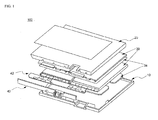
- FIG. 1 is an exploded view typically showing a conventional battery pack having a 2P-2S structure.
- a conventional battery pack 100 is configured so that four battery cells 30 are electrically connected to each other in a 2P-2S structure.
- a protection circuit module 40 and a flexible protection circuit board (FPCB) 42 are connected to the upper ends of the battery cells to control the operation of the battery pack.
- double-sided adhesive tapes 34 are provided between the battery cells 30 and between the battery cells 30 and a lower case 10.
- the battery cells 30, the protection circuit module 40, the flexible protection circuit board 42 are sealed by an upper case 20 and the lower case 10.
- the protection circuit module 40 includes an additional element (not shown) to adjust voltage unbalance between the battery cells due to series electrical connection between the battery cells.
- a battery pack mounted in a laptop computer requires high power and capacity.
- a conventional cylindrical battery pack including a plurality of cylindrical battery cells has generally been used.
- the size of a laptop computer has been reduced, and therefore, there is a high necessity for a slim type battery pack.
- the present invention has been made to solve the above problems, and other technical problems that have yet to be resolved.
- a battery pack including (a) a battery cell array including three or fewer battery cells, each of which has an electrode assembly of a cathode/separator/anode structure disposed in a battery case together with an electrolyte in a sealed state, arranged in the lateral direction, the battery cells having a current capacity of 3 amperes (Ah) or more and being electrically connected in series to each other, (b) a protection circuit module (PCM) connected to the upper end of the battery cell array to control the operation of the battery pack, the protection circuit module including a protection circuit, from which a function to adjust voltage unbalance between the battery cells is removed, and (c) a pack case in which the battery cell array and the protection circuit module are disposed.
- PCM protection circuit module
- the battery pack according to the present invention includes the battery cells each having a current capacity of 3 amperes or more. Consequently, the battery pack according to the present invention uses three or fewer battery cells as compared with a conventional battery pack for laptop computers including four or more battery cells each having a current capacity of 2.5 amperes, and therefore, it is possible to assemble the battery pack using a simpler method.
- the battery cells are electrically connected in series to each other. Consequently, it is possible to reduce a battery pack defect rate due to voltage unbalance between the battery cells as compared with a conventional battery pack for laptop computers including battery cells electrically connected in parallel to each other.
- the series electrical connection between the battery cells is not particularly restricted so long as parallel electrical connection between two or more battery cells is not included.
- the battery cells are electrically connected in series to each other in a 1 parallel (P)-2 series (S) structure or in a 1P-3S structure.
- the series electrical connection structure is achieved using three or fewer battery cells. Consequently, it is possible to manufacture a high capacity battery pack having a more compact structure.
- the battery pack may further include a spacer mounted between the pack case and the battery cell array to provide a space accommodating the increase in thickness of the battery cell array during charge and discharge of the battery pack.
- the thickness of a secondary battery after 300 to 500 cycles of charge and discharge of the secondary battery is 5 to 10% greater than the thickness of the secondary battery before charge and discharge of the secondary battery.
- the spacer may have a thickness equivalent to 5 to 10%, preferably 7 to 8%, of the thickness of the battery cell array so as to offset the increase in thickness of the secondary battery.
- the pack case may be formed of a plastic material
- the spacer may be formed of a sheet member or a plastic material.
- the pack case according to the present invention can reduce the weight of the battery pack and can be easily applied to complex products as compared with a pack case formed of a metal material.
- the sheet member may be formed of, preferably, a Nomex material.
- Nomex is a trademark of a product manufactured and sold by E.I. du Pont de Nemours and Company.
- the spacer is provided at the top or bottom thereof with an adhesive, by which the spacer is bonded to the outer side of the battery cell array. Consequently, it is possible to effectively prevent the spacer from moving out of position.
- the spacer may be formed of a double-sided adhesive tape.
- the spacer may be mounted to the tops and bottoms of the battery cells at two or more edges thereof in a state in which the spacer has a predetermined width.
- the spacer may have a width equivalent to 5 to 20% of the width of each of the battery cells.
- the spacer may be damaged since the width of the spacer is narrow.
- the width of the spacer is greater than 20% of the width of each of the battery cells, a space to offset the increase in thickness of the battery cell array becomes insufficient, which is not preferable.
- the spacer may be a strip member.
- the spacer may be formed to have a lattice structure in which the spacer is simultaneously mounted to the battery cells in a state in which the tops or bottoms of the battery cells are exposed.
- the protection circuit module may include connection terminals connected to electrode terminals of the battery cells by resistance welding, metal plates to electrically connect the battery cells to each other, and a protection circuit to control the operation of the battery pack.
- the metal plates to electrically connect the battery cells to each other may be formed at the top of the protection circuit module.
- this structure it is possible to easily manufacture the PCM and to easily assemble the battery pack as compared with a conventional battery pack structure in which metal wires are formed at a layer in the protection circuit of the PCM so as to electrically connect battery cells to each other.
- electrical connection regions between cathode terminals of the battery cells and the protection circuit module may be configured to have a structure in which conductive plates attached to tops of the respective connection terminals of the protection circuit module are welded so that the conductive plates wrap the respective cathode terminals of the battery cells.
- connection terminals of the protection circuit module and the cathode terminals of the battery cells are directly connected to each other with high welding coupling force via the conductive plates, which are configured to have a specific structure, and the battery cells are electrically connected in series to each other via the metal plates included in the protection circuit module. Consequently, it is possible to easily manufacture a high capacity battery pack through the use of a simple method.
- the battery cells are arranged in the lateral direction to constitute a battery cell array, the battery cell array and a PCM are disposed at a pack case, and electrode terminals of the battery cells and connection terminals of the PCM are connected to each other by resistance welding, thereby manufacturing a desired battery pack.
- the conductive plates may be attached to the connection terminals of the protection circuit module so that the conductive plates can be bent, the conductive plates may be bent in a bracket shape in a state in which the cathode terminals of the battery cells are placed on the conductive plates, and resistance welding may be carried out from above the bent portions of the conductive plates, thereby achieving physical coupling and electrical connection between the connection terminals of the protection circuit module and the cathode terminals of the battery cells.
- the shape of the conductive plates is not particularly restricted so long as the conductive plates can be easily bent.
- the conductive plates may be formed in an L shape in a state in which the conductive plates are attached to the corresponding connection terminals of the protection circuit module.
- Each of the conductive plates may include a first connection part attached to the top of a corresponding one of the connection terminals of the protection circuit module and a second connection part attached to the top of the cathode terminal of a corresponding one of the battery cells. Consequently, the connection between the cathode terminals of the battery cells and the connection terminals of the protection circuit module is more securely achieved. In addition, when external force is applied to the battery pack, deformation of the electrical connection regions between the cathode terminals of the battery cells and the protection circuit module is prevented.
- each of the conductive plates is not particularly restricted so long as the conductive plates can provide high coupling force when the conductive plates are welded as described above.
- each of the conductive plates is a nickel plate, and each of the cathode terminals of the battery cells is an aluminum terminal.
- the pack case includes a lower case, at which the battery cell array and the protection circuit module are disposed, and an upper case to cover the lower case so as to fix the battery cell array and the protection circuit module in place.
- the lower case may be partitioned into a battery cell mounting part, at which the battery cells are disposed, and a protection circuit module mounting part, at which the protection circuit module is disposed, and a partition wall may be formed at the interface between the battery cell mounting part and the protection circuit module mounting part. Also, openings, through which electrode terminals of the battery cells are exposed toward the protection circuit module, may be formed at portions of the partition wall corresponding to electrical connection regions between the electrode terminals of the battery cells and the protection circuit module.
- the openings, through which the electrode terminals of the battery cells are exposed toward the protection circuit module are formed at portions of the partition wall corresponding to the electrical connection regions between the electrode terminals of the battery cells and the protection circuit module, it is possible to easily weld the electrode terminals of the battery cells, which are exposed through the openings, to the connection terminals of the protection circuit module.
- the height of the partition wall may be sufficient to fully isolate the battery cell mounting part and the protection circuit module mounting part from each other.
- the protection circuit module mounting part may be configured to have a structure including support parts to support the electrical connection regions between the electrode terminals of the battery cells and the protection circuit module.
- the shape of the support parts is not particularly restricted so long as the support parts can easily support the electrical connection regions between the electrode terminals of the battery cells and the protection circuit module.
- the support parts may be formed on the lower case in the shape of an upward protrusion.
- the support parts are formed in the shape of a cross-shaped protrusion. Consequently, it is possible for the support parts to more stably support the electrical connection regions between the electrode terminals of the battery cells and the protection circuit module during resistance welding between the electrode terminals of the battery cells and the protection circuit module.
- any battery cells may be used in various manners irrespective of the kind and shape of the battery cells.
- a pouch-shaped secondary battery of an approximately hexahedral structure having a small thickness to width ratio, preferably a pouch-shaped lithium secondary battery, may be used as each battery cell of the battery pack.
- an external input and output terminal which inputs electric current to the battery pack, outputs electric current from the battery pack, and transmits and receives information, may be mounted at the front of the protection circuit module in a depressed form.
- the battery pack can be stably connected to an external device through the external input and output terminal since the external input and output terminal is configured to have a connector structure.
- a laptop computer including the battery pack with the above-stated construction as a power source.
- the battery pack according to the present invention may be manufactured so as to provide power and capacity required by a device by varying the number of battery cells constituting the battery pack.
- the battery pack according to the present invention can be applied to various devices requiring variable battery capacities in addition to the laptop computer.
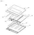
- FIG. 2 is an exploded view typically showing a battery pack according to an embodiment of the present invention.
- a battery pack 100a includes a battery cell array 30a including two battery cells 32a, having a current capacity of 3 amperes, arranged in the lateral direction in a state in which the battery cells 32a are electrically connected in series to each other, a protection circuit module 40a connected to the upper end of the battery cell array 30a, and pack cases 10a and 20a between which the battery cell array 30a and the protection circuit module 40a are disposed.
- the protection circuit module 40a includes a protection circuit, from which a function to adjust voltage unbalance between the battery cells is removed.
- Each of the battery cells 32a is a pouch-shaped secondary battery configured so that an electrode assembly having a cathode/separator/anode structure is disposed in a battery case together with an electrolyte in a sealed state.
- the pouch-shaped secondary battery is generally configured to have a plate-shaped structure, i.e. an approximately hexahedral structure having a small thickness to width ratio.
- the pouch-shaped secondary battery includes a pouch-shaped battery case.
- the battery case is configured to have a laminate sheet structure in which an outer coating layer formed of a polymer resin exhibiting high durability, a barrier layer formed of a metal material blocking moisture or air, and an inner sealant layer formed of a polymer resin that can be thermally welded are sequentially stacked.
- the pack cases include a lower case 10a to which the battery cell array 30a and the protection circuit module 40a are mounted and an upper case 20a disposed above the lower case 10a to fix the battery cell array 30a and the protection circuit module 40a in place.
- FIG. 3 and 4 are exploded views typically showing battery packs according to other embodiments of the present invention.
- a battery pack 100b of FIG. 3 is identical in structure to the battery pack 100a of FIG. 2 except that three battery cells 32b are electrically connected to series to each other, and therefore, a detailed description thereof will not be given.
- an upper case 20c and a lower case 10c are formed of a plastic material, and spacers 50c and 52c are formed of a double-sided adhesive tape, such as Nomex.
- the spacers 50c and 52c include an upper spacer 52c mounted to the top of a battery cell array 30c and a lower spacer 50c mounted to the bottom of the battery cell array 30c.
- Each of the spacers has a thickness equivalent to approximately 8% of the thickness of each battery cell 32c.
- FIG. 5 is a perspective view typically showing a structure in which the spacer is mounted to the upper end of the battery cell array of FIG. 4 .
- the upper spacer 52c includes first upper spacers 523c and 524c, each of which has a width w equivalent to approximately 20% of the width W of each of the battery cells 32c, and second upper spacers 521c and 522c, each of which has a width w equivalent to approximately 10% of the width W of each of the battery cells 32c.
- the thickness of the battery cells 32c increased during charge and discharge of the battery cells 32c is offset in spaces S between the first upper spacers 523c and 524c and the second upper spacers 521c and 522c. As a result, overall thickness of the battery pack does not change.
- first upper spacers 523c and 524c and the second upper spacers 521c and 522c are mounted to the tops of the corresponding battery cells 32c at two edges thereof.
- the first upper spacers 523c and 524c and the second upper spacers 521c and 522c are formed in the shape of an elongated strip.
- FIG. 6 is an exploded view typically showing a battery pack according to a further embodiment of the present invention
- FIG. 7 is an enlarged view typically showing a spacer of FIG. 6 .
- spacers 50d and 52d are mounted to the tops and bottoms of battery cells 32d at four edges thereof.
- the spacers 50d and 52d are formed to have a lattice structure in which the spacers 50d and 52d are simultaneously mounted to the battery cells 32d in a state in which the tops or bottoms of the battery cells 32d are exposed.
- FIG. 8 is an enlarged view typically showing a region A of FIG. 5
- FIG. 9 is an enlarged view typically showing a region B of FIG. 5 .
- the lower case 10c is partitioned into a battery cell mounting part 12c, at which the battery cells 32c are disposed, and a protection circuit module mounting part 14c, at which the protection circuit module 40c is disposed.
- a partition wall 16c is formed at the interface between the battery cell mounting part 12c and the protection circuit module mounting part 14c. Openings 18c, through which anode terminals 34c of the battery cells 32c are exposed toward the protection circuit module 40c, are formed at portions of the partition wall 16 corresponding to electrical connection regions between the anode terminals 34c of the battery cells 32c and the protection circuit module 40c.
- the partition wall 16c has a height h sufficient to fully isolate the battery cell mounting part 12c and the protection circuit module 40c from each other. According to circumstances, a corresponding partition wall may be formed at the upper case (not shown) so as to achieve the above-mentioned isolation.
- the protection circuit module 40c includes connection terminals 42c connected to cathode terminals 33c of the battery cells 32c by resistance welding, metal plates (not shown) to electrically connect the connection terminals 42c to each other, and a protection circuit (not shown) to control the operation of the battery pack.
- An electrical connection region B between the cathode terminal 33c of each of the battery cells 32c and the protection circuit module 40c is configured to have a structure in which a conductive plate 41c attached to a corresponding one of the connection terminals 42c of the protection circuit module 40c wraps the cathode terminal 33c of each of the battery cells 32c.
- the conductive plate 41c which may be a nickel plate, includes a first connection part 43c attached to the top of the corresponding connection terminal 42c of the protection circuit module 40c and a second connection part 44c attached to the top of the cathode terminal, which may be an aluminum terminal, of the corresponding battery cell 32.
- the conductive plate 41c is attached to the top of the corresponding connection terminal 42c of the protection circuit module 40c in an L shape.
- the conductive plate 41 is bent in a bracket shape in a state in which the cathode terminal 33c of the corresponding battery cell 32c is placed at the top of the first connection part 43c of the conductive plate 41c, and then resistance welding is carried out from above the second connection part 44c, which is a bent portion of the conductive plate 4 1 c.
- an external input and output terminal i.e. a connector 46c, which inputs electric current to the battery pack, outputs electric current from the battery pack, and transmits and receives information, is mounted at the front of the protection circuit module 40c in a depressed form.
- FIG. 10 is a perspective view typically showing the lower case
- FIG. 11 is an enlarged view typically showing a region C of FIG. 10 .
- an external input and output terminal mounting part 15c in which an external input and output terminal 46c, which inputs electric current to the battery pack, outputs electric current from the battery pack, and transmits and receives information, is mounted, is formed at the protection circuit module mounting part 14c of the lower case 10c.
- a support part 13c to support the electrical connection region between the cathode terminal 33c of each of the battery cells 32c and the protection circuit module 40c is formed on the lower case 10c in the shape of an upward cross-shaped protrusion in a state in which the support part 13 is connected to the partition wall 16c.
- the support part 13 appropriately supports downward pressure applied by a welding tip (not shown) to be located above the cathode terminal 33c of each of the battery cells 32 during resistance welding, thereby providing high welding force.
- FIG. 12 is a typical view showing a resistance welding structure of the present invention.
- electric current generated from a resistance welding rod 440 during resistance welding between a nickel plate 430, located at the top of a protection circuit board 410, and an aluminum terminal 420 flows from the nickel plate 430, resistance of which is high, to the aluminum terminal 420, resistance of which is low, and flows back to the nickel plate 430.
- heat is generated from the interface between the aluminum terminal 420 and the nickel plate 430 due to resistance difference therebetween with the result that the resistance welding between the nickel plate 430 and the aluminum terminal 420 is easily achieved.
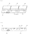
- FIG. 13 is a partial perspective view typically showing a structure in which a plurality of pouch-shaped battery cells according to another embodiment of the present invention is electrically connected to each other
- FIG. 14 is an enlarged plan view typically showing a protection circuit module (PCM) of FIG. 13 .
- PCM protection circuit module
- metal plates 402d to electrically connect battery cells 32d, 34d and 36d to each other are formed at the top of a protection circuit module 40d in a structure in which an anode terminal 324d of the first battery cell 32d is connected in series to a cathode terminal 342d of the second battery cell 34d.
- the protection circuit module 40d includes a PCM main body 401d having a protection circuit to control overcharge, overdischarge and overcurrent, connection terminals 404d and 407d formed at positions of the PCM main body 401d corresponding to the electrode terminals of the battery cells 32d, 34d and 36d so as to directly electrically connect the battery cells 32d, 34d and 36d to each other, metal plates 405d formed at the top of the PCM main body 401 d to electrically connect the connection terminals 404d and 407d to each other, and an external input and output terminal 403d to input electric current to the battery pack, to output electric current from the battery pack, and to transmit and receive information, are mounted at the front of the PCM main body 401 in a depressed form.
- the battery pack according to the present invention includes three or fewer battery cells, each of which has a current capacity of 3 amperes or more, electrically connected in series to each other in a state in which the battery cells are arranged in the lateral direction so as to provide high capacity. Consequently, it is possible to manufacture a high capacity battery pack without using a parallel connection structure and, at the same time, to greatly reduce a defect rate due to voltage unbalance between the battery cells when the battery cells are connected in parallel to each other.
- the protection circuit module does not include an element to adjust voltage unbalance between the battery cells. Consequently, it is possible to manufacture a battery pack using a simple and easy method and to reduce the number of parts constituting the battery pack, thereby greatly reducing manufacturing costs.
Landscapes
- Chemical & Material Sciences (AREA)
- Chemical Kinetics & Catalysis (AREA)
- Electrochemistry (AREA)
- General Chemical & Material Sciences (AREA)
- Engineering & Computer Science (AREA)
- Manufacturing & Machinery (AREA)
- Battery Mounting, Suspending (AREA)
- Secondary Cells (AREA)
Applications Claiming Priority (2)
| Application Number | Priority Date | Filing Date | Title |
|---|---|---|---|
| KR1020100009167A KR101230495B1 (ko) | 2010-02-01 | 2010-02-01 | 대용량의 전지팩 |
| PCT/KR2011/000537 WO2011093638A2 (fr) | 2010-02-01 | 2011-01-26 | Bloc d'éléments d'accumulateur de grande capacité |
Publications (3)
| Publication Number | Publication Date |
|---|---|
| EP2506335A2 true EP2506335A2 (fr) | 2012-10-03 |
| EP2506335A4 EP2506335A4 (fr) | 2014-05-07 |
| EP2506335B1 EP2506335B1 (fr) | 2017-02-22 |
Family
ID=44319977
Family Applications (1)
| Application Number | Title | Priority Date | Filing Date |
|---|---|---|---|
| EP11737277.1A Active EP2506335B1 (fr) | 2010-02-01 | 2011-01-26 | Bloc d'éléments d'accumulateur de grande capacité |
Country Status (6)
| Country | Link |
|---|---|
| US (1) | US9088033B2 (fr) |
| EP (1) | EP2506335B1 (fr) |
| JP (1) | JP5636443B2 (fr) |
| KR (1) | KR101230495B1 (fr) |
| CN (1) | CN102687306B (fr) |
| WO (1) | WO2011093638A2 (fr) |
Cited By (3)
| Publication number | Priority date | Publication date | Assignee | Title |
|---|---|---|---|---|
| EP2579359A4 (fr) * | 2010-05-28 | 2014-07-23 | Lg Chemical Ltd | Bloc-batterie possédant une structure compacte |
| EP2595213A4 (fr) * | 2010-07-16 | 2016-06-01 | Lg Chemical Ltd | Boîtier à la structure innovante |
| EP3886203A1 (fr) * | 2020-03-27 | 2021-09-29 | Samsung SDI Co., Ltd. | Procédé d'assemblage d'un empilement de cellules de batterie prismatiques, empilement de cellules de batterie prismatiques, module de batterie et véhicule incluant un bloc-batterie comprenant au moins un module de batterie |
Families Citing this family (8)
| Publication number | Priority date | Publication date | Assignee | Title |
|---|---|---|---|---|
| KR101293943B1 (ko) * | 2009-12-22 | 2013-08-07 | 주식회사 엘지화학 | 강성이 향상된 전지팩 |
| KR101483131B1 (ko) | 2013-07-09 | 2015-01-15 | 삼성에스디아이 주식회사 | 전지 팩 |
| US9304550B1 (en) | 2014-09-29 | 2016-04-05 | Apple Inc. | Adhesive bond with integrated release mechanism |
| JP2018510488A (ja) * | 2015-02-27 | 2018-04-12 | リテルヒューズ・インク | バッテリーパック保護のための相互接続部 |
| US10110025B2 (en) | 2016-01-26 | 2018-10-23 | Microsoft Technology Licensing, Llc | Enhanced parallel protection circuit |
| CN106207040A (zh) * | 2016-08-31 | 2016-12-07 | 河南新太行电源股份有限公司 | 一种电池弹性连接装置 |
| KR102669975B1 (ko) * | 2019-02-21 | 2024-05-29 | 삼성에스디아이 주식회사 | 배터리 팩 |
| CN113451633B (zh) * | 2020-03-27 | 2024-07-16 | 三星Sdi株式会社 | 电池单元的堆叠及其组装方法、电池模块和车辆 |
Family Cites Families (14)
| Publication number | Priority date | Publication date | Assignee | Title |
|---|---|---|---|---|
| JP4214450B2 (ja) | 2002-06-03 | 2009-01-28 | 日本電気株式会社 | モジュール |
| US7625665B2 (en) | 2004-11-30 | 2009-12-01 | Samsung Sdi Co., Ltd. | Secondary battery module and end-plate used in the same |
| WO2006068373A1 (fr) | 2004-12-24 | 2006-06-29 | Lg Chem, Ltd. | Module de batterie secondaire |
| JP4586656B2 (ja) * | 2005-07-05 | 2010-11-24 | トヨタ自動車株式会社 | フィルム外装型リチウム電池 |
| JP4208865B2 (ja) | 2005-07-07 | 2009-01-14 | 株式会社東芝 | 非水電解質電池及び電池パック |
| CN102931434B (zh) | 2005-10-20 | 2015-09-16 | 三菱化学株式会社 | 锂二次电池以及其中使用的非水电解液 |
| JP2007194209A (ja) | 2005-12-22 | 2007-08-02 | Mitsubishi Chemicals Corp | リチウム二次電池及びそれを連結した組電池 |
| JP5154454B2 (ja) * | 2006-03-06 | 2013-02-27 | エルジー・ケム・リミテッド | 電池モジュール |
| JP4165586B2 (ja) | 2006-08-02 | 2008-10-15 | ソニー株式会社 | 電池パック |
| KR100892046B1 (ko) | 2006-09-18 | 2009-04-07 | 주식회사 엘지화학 | 전지모듈 및 그것을 포함하고 있는 중대형 전지팩 |
| US20080299445A1 (en) * | 2007-05-31 | 2008-12-04 | Densei-Lambda K.K. | Secondary battery pack |
| KR101161135B1 (ko) * | 2007-06-28 | 2012-06-29 | 주식회사 엘지화학 | 중대형 전지모듈 |
| KR100983012B1 (ko) * | 2007-10-13 | 2010-09-17 | 주식회사 엘지화학 | 기계적 접속방식에 기반한 이차전지 팩 |
| EP2212941B1 (fr) * | 2007-11-21 | 2015-01-14 | LG Chem, Ltd. | Module de batterie à sécurité améliorée et bloc batterie de taille moyenne ou grande le contenant |
-
2010
- 2010-02-01 KR KR1020100009167A patent/KR101230495B1/ko active Active
-
2011
- 2011-01-26 WO PCT/KR2011/000537 patent/WO2011093638A2/fr not_active Ceased
- 2011-01-26 EP EP11737277.1A patent/EP2506335B1/fr active Active
- 2011-01-26 US US13/520,130 patent/US9088033B2/en active Active
- 2011-01-26 JP JP2012547036A patent/JP5636443B2/ja active Active
- 2011-01-26 CN CN201180005298.XA patent/CN102687306B/zh active Active
Cited By (4)
| Publication number | Priority date | Publication date | Assignee | Title |
|---|---|---|---|---|
| EP2579359A4 (fr) * | 2010-05-28 | 2014-07-23 | Lg Chemical Ltd | Bloc-batterie possédant une structure compacte |
| US9331313B2 (en) | 2010-05-28 | 2016-05-03 | Lg Chem, Ltd. | Battery pack of compact structure |
| EP2595213A4 (fr) * | 2010-07-16 | 2016-06-01 | Lg Chemical Ltd | Boîtier à la structure innovante |
| EP3886203A1 (fr) * | 2020-03-27 | 2021-09-29 | Samsung SDI Co., Ltd. | Procédé d'assemblage d'un empilement de cellules de batterie prismatiques, empilement de cellules de batterie prismatiques, module de batterie et véhicule incluant un bloc-batterie comprenant au moins un module de batterie |
Also Published As
| Publication number | Publication date |
|---|---|
| WO2011093638A3 (fr) | 2011-11-10 |
| CN102687306B (zh) | 2015-01-21 |
| CN102687306A (zh) | 2012-09-19 |
| KR20110089670A (ko) | 2011-08-09 |
| JP2013516044A (ja) | 2013-05-09 |
| US20120300396A1 (en) | 2012-11-29 |
| JP5636443B2 (ja) | 2014-12-03 |
| EP2506335A4 (fr) | 2014-05-07 |
| WO2011093638A2 (fr) | 2011-08-04 |
| EP2506335B1 (fr) | 2017-02-22 |
| US9088033B2 (en) | 2015-07-21 |
| KR101230495B1 (ko) | 2013-02-06 |
Similar Documents
| Publication | Publication Date | Title |
|---|---|---|
| EP2506335B1 (fr) | Bloc d'éléments d'accumulateur de grande capacité | |
| EP2533319B1 (fr) | Corps de liaison d'éléments d'accumulateur ayant une nouvelle structure et bloc d'éléments d'accumulateur le comprenant | |
| US9331313B2 (en) | Battery pack of compact structure | |
| US9041350B2 (en) | Battery pack having improved strength | |
| EP2579358B1 (fr) | Bloc-batterie de structure nouvelle | |
| KR101040975B1 (ko) | 신규한 구조의 이차전지 팩 | |
| EP2595213B1 (fr) | Boîtier à la structure innovante | |
| KR20150107475A (ko) | 배터리 보호회로모듈 및 이를 구비하는 배터리팩 | |
| US9240618B2 (en) | Rechargeable battery and battery module | |
| KR20100082677A (ko) | 신규한 구조의 대용량 전지팩 | |
| US20140349141A1 (en) | Battery pack | |
| KR102195728B1 (ko) | 배터리 팩 |
Legal Events
| Date | Code | Title | Description |
|---|---|---|---|
| PUAI | Public reference made under article 153(3) epc to a published international application that has entered the european phase |
Free format text: ORIGINAL CODE: 0009012 |
|
| 17P | Request for examination filed |
Effective date: 20120625 |
|
| AK | Designated contracting states |
Kind code of ref document: A2 Designated state(s): AL AT BE BG CH CY CZ DE DK EE ES FI FR GB GR HR HU IE IS IT LI LT LU LV MC MK MT NL NO PL PT RO RS SE SI SK SM TR |
|
| DAX | Request for extension of the european patent (deleted) | ||
| A4 | Supplementary search report drawn up and despatched |
Effective date: 20140407 |
|
| RIC1 | Information provided on ipc code assigned before grant |
Ipc: H01M 2/34 20060101ALI20140401BHEP Ipc: H01M 2/10 20060101AFI20140401BHEP Ipc: H01M 2/20 20060101ALI20140401BHEP Ipc: H01M 10/02 20060101ALI20140401BHEP |
|
| 17Q | First examination report despatched |
Effective date: 20150407 |
|
| GRAP | Despatch of communication of intention to grant a patent |
Free format text: ORIGINAL CODE: EPIDOSNIGR1 |
|
| STAA | Information on the status of an ep patent application or granted ep patent |
Free format text: STATUS: GRANT OF PATENT IS INTENDED |
|
| INTG | Intention to grant announced |
Effective date: 20161115 |
|
| GRAS | Grant fee paid |
Free format text: ORIGINAL CODE: EPIDOSNIGR3 |
|
| GRAA | (expected) grant |
Free format text: ORIGINAL CODE: 0009210 |
|
| STAA | Information on the status of an ep patent application or granted ep patent |
Free format text: STATUS: THE PATENT HAS BEEN GRANTED |
|
| AK | Designated contracting states |
Kind code of ref document: B1 Designated state(s): AL AT BE BG CH CY CZ DE DK EE ES FI FR GB GR HR HU IE IS IT LI LT LU LV MC MK MT NL NO PL PT RO RS SE SI SK SM TR |
|
| REG | Reference to a national code |
Ref country code: GB Ref legal event code: FG4D |
|
| REG | Reference to a national code |
Ref country code: CH Ref legal event code: EP |
|
| REG | Reference to a national code |
Ref country code: AT Ref legal event code: REF Ref document number: 869896 Country of ref document: AT Kind code of ref document: T Effective date: 20170315 |
|
| REG | Reference to a national code |
Ref country code: IE Ref legal event code: FG4D |
|
| REG | Reference to a national code |
Ref country code: DE Ref legal event code: R096 Ref document number: 602011035210 Country of ref document: DE |
|
| REG | Reference to a national code |
Ref country code: LT Ref legal event code: MG4D |
|
| REG | Reference to a national code |
Ref country code: NL Ref legal event code: MP Effective date: 20170222 |
|
| REG | Reference to a national code |
Ref country code: AT Ref legal event code: MK05 Ref document number: 869896 Country of ref document: AT Kind code of ref document: T Effective date: 20170222 |
|
| PG25 | Lapsed in a contracting state [announced via postgrant information from national office to epo] |
Ref country code: LT Free format text: LAPSE BECAUSE OF FAILURE TO SUBMIT A TRANSLATION OF THE DESCRIPTION OR TO PAY THE FEE WITHIN THE PRESCRIBED TIME-LIMIT Effective date: 20170222 Ref country code: HR Free format text: LAPSE BECAUSE OF FAILURE TO SUBMIT A TRANSLATION OF THE DESCRIPTION OR TO PAY THE FEE WITHIN THE PRESCRIBED TIME-LIMIT Effective date: 20170222 Ref country code: GR Free format text: LAPSE BECAUSE OF FAILURE TO SUBMIT A TRANSLATION OF THE DESCRIPTION OR TO PAY THE FEE WITHIN THE PRESCRIBED TIME-LIMIT Effective date: 20170523 Ref country code: NO Free format text: LAPSE BECAUSE OF FAILURE TO SUBMIT A TRANSLATION OF THE DESCRIPTION OR TO PAY THE FEE WITHIN THE PRESCRIBED TIME-LIMIT Effective date: 20170522 Ref country code: FI Free format text: LAPSE BECAUSE OF FAILURE TO SUBMIT A TRANSLATION OF THE DESCRIPTION OR TO PAY THE FEE WITHIN THE PRESCRIBED TIME-LIMIT Effective date: 20170222 |
|
| PG25 | Lapsed in a contracting state [announced via postgrant information from national office to epo] |
Ref country code: NL Free format text: LAPSE BECAUSE OF FAILURE TO SUBMIT A TRANSLATION OF THE DESCRIPTION OR TO PAY THE FEE WITHIN THE PRESCRIBED TIME-LIMIT Effective date: 20170222 Ref country code: RS Free format text: LAPSE BECAUSE OF FAILURE TO SUBMIT A TRANSLATION OF THE DESCRIPTION OR TO PAY THE FEE WITHIN THE PRESCRIBED TIME-LIMIT Effective date: 20170222 Ref country code: SE Free format text: LAPSE BECAUSE OF FAILURE TO SUBMIT A TRANSLATION OF THE DESCRIPTION OR TO PAY THE FEE WITHIN THE PRESCRIBED TIME-LIMIT Effective date: 20170222 Ref country code: ES Free format text: LAPSE BECAUSE OF FAILURE TO SUBMIT A TRANSLATION OF THE DESCRIPTION OR TO PAY THE FEE WITHIN THE PRESCRIBED TIME-LIMIT Effective date: 20170222 Ref country code: AT Free format text: LAPSE BECAUSE OF FAILURE TO SUBMIT A TRANSLATION OF THE DESCRIPTION OR TO PAY THE FEE WITHIN THE PRESCRIBED TIME-LIMIT Effective date: 20170222 Ref country code: LV Free format text: LAPSE BECAUSE OF FAILURE TO SUBMIT A TRANSLATION OF THE DESCRIPTION OR TO PAY THE FEE WITHIN THE PRESCRIBED TIME-LIMIT Effective date: 20170222 Ref country code: PT Free format text: LAPSE BECAUSE OF FAILURE TO SUBMIT A TRANSLATION OF THE DESCRIPTION OR TO PAY THE FEE WITHIN THE PRESCRIBED TIME-LIMIT Effective date: 20170622 Ref country code: BG Free format text: LAPSE BECAUSE OF FAILURE TO SUBMIT A TRANSLATION OF THE DESCRIPTION OR TO PAY THE FEE WITHIN THE PRESCRIBED TIME-LIMIT Effective date: 20170522 |
|
| PG25 | Lapsed in a contracting state [announced via postgrant information from national office to epo] |
Ref country code: SK Free format text: LAPSE BECAUSE OF FAILURE TO SUBMIT A TRANSLATION OF THE DESCRIPTION OR TO PAY THE FEE WITHIN THE PRESCRIBED TIME-LIMIT Effective date: 20170222 Ref country code: CZ Free format text: LAPSE BECAUSE OF FAILURE TO SUBMIT A TRANSLATION OF THE DESCRIPTION OR TO PAY THE FEE WITHIN THE PRESCRIBED TIME-LIMIT Effective date: 20170222 Ref country code: RO Free format text: LAPSE BECAUSE OF FAILURE TO SUBMIT A TRANSLATION OF THE DESCRIPTION OR TO PAY THE FEE WITHIN THE PRESCRIBED TIME-LIMIT Effective date: 20170222 Ref country code: EE Free format text: LAPSE BECAUSE OF FAILURE TO SUBMIT A TRANSLATION OF THE DESCRIPTION OR TO PAY THE FEE WITHIN THE PRESCRIBED TIME-LIMIT Effective date: 20170222 |
|
| REG | Reference to a national code |
Ref country code: DE Ref legal event code: R097 Ref document number: 602011035210 Country of ref document: DE |
|
| PG25 | Lapsed in a contracting state [announced via postgrant information from national office to epo] |
Ref country code: SM Free format text: LAPSE BECAUSE OF FAILURE TO SUBMIT A TRANSLATION OF THE DESCRIPTION OR TO PAY THE FEE WITHIN THE PRESCRIBED TIME-LIMIT Effective date: 20170222 Ref country code: PL Free format text: LAPSE BECAUSE OF FAILURE TO SUBMIT A TRANSLATION OF THE DESCRIPTION OR TO PAY THE FEE WITHIN THE PRESCRIBED TIME-LIMIT Effective date: 20170222 Ref country code: DK Free format text: LAPSE BECAUSE OF FAILURE TO SUBMIT A TRANSLATION OF THE DESCRIPTION OR TO PAY THE FEE WITHIN THE PRESCRIBED TIME-LIMIT Effective date: 20170222 |
|
| REG | Reference to a national code |
Ref country code: FR Ref legal event code: PLFP Year of fee payment: 8 |
|
| PLBE | No opposition filed within time limit |
Free format text: ORIGINAL CODE: 0009261 |
|
| STAA | Information on the status of an ep patent application or granted ep patent |
Free format text: STATUS: NO OPPOSITION FILED WITHIN TIME LIMIT |
|
| 26N | No opposition filed |
Effective date: 20171123 |
|
| PG25 | Lapsed in a contracting state [announced via postgrant information from national office to epo] |
Ref country code: SI Free format text: LAPSE BECAUSE OF FAILURE TO SUBMIT A TRANSLATION OF THE DESCRIPTION OR TO PAY THE FEE WITHIN THE PRESCRIBED TIME-LIMIT Effective date: 20170222 Ref country code: IT Free format text: LAPSE BECAUSE OF FAILURE TO SUBMIT A TRANSLATION OF THE DESCRIPTION OR TO PAY THE FEE WITHIN THE PRESCRIBED TIME-LIMIT Effective date: 20170222 |
|
| REG | Reference to a national code |
Ref country code: CH Ref legal event code: PL |
|
| PG25 | Lapsed in a contracting state [announced via postgrant information from national office to epo] |
Ref country code: LU Free format text: LAPSE BECAUSE OF NON-PAYMENT OF DUE FEES Effective date: 20180126 |
|
| REG | Reference to a national code |
Ref country code: IE Ref legal event code: MM4A |
|
| REG | Reference to a national code |
Ref country code: BE Ref legal event code: MM Effective date: 20180131 |
|
| PG25 | Lapsed in a contracting state [announced via postgrant information from national office to epo] |
Ref country code: BE Free format text: LAPSE BECAUSE OF NON-PAYMENT OF DUE FEES Effective date: 20180131 Ref country code: CH Free format text: LAPSE BECAUSE OF NON-PAYMENT OF DUE FEES Effective date: 20180131 Ref country code: LI Free format text: LAPSE BECAUSE OF NON-PAYMENT OF DUE FEES Effective date: 20180131 |
|
| PG25 | Lapsed in a contracting state [announced via postgrant information from national office to epo] |
Ref country code: IE Free format text: LAPSE BECAUSE OF NON-PAYMENT OF DUE FEES Effective date: 20180126 |
|
| PG25 | Lapsed in a contracting state [announced via postgrant information from national office to epo] |
Ref country code: MC Free format text: LAPSE BECAUSE OF FAILURE TO SUBMIT A TRANSLATION OF THE DESCRIPTION OR TO PAY THE FEE WITHIN THE PRESCRIBED TIME-LIMIT Effective date: 20170222 |
|
| PG25 | Lapsed in a contracting state [announced via postgrant information from national office to epo] |
Ref country code: MT Free format text: LAPSE BECAUSE OF NON-PAYMENT OF DUE FEES Effective date: 20180126 |
|
| PG25 | Lapsed in a contracting state [announced via postgrant information from national office to epo] |
Ref country code: TR Free format text: LAPSE BECAUSE OF FAILURE TO SUBMIT A TRANSLATION OF THE DESCRIPTION OR TO PAY THE FEE WITHIN THE PRESCRIBED TIME-LIMIT Effective date: 20170222 |
|
| PG25 | Lapsed in a contracting state [announced via postgrant information from national office to epo] |
Ref country code: HU Free format text: LAPSE BECAUSE OF FAILURE TO SUBMIT A TRANSLATION OF THE DESCRIPTION OR TO PAY THE FEE WITHIN THE PRESCRIBED TIME-LIMIT; INVALID AB INITIO Effective date: 20110126 |
|
| PG25 | Lapsed in a contracting state [announced via postgrant information from national office to epo] |
Ref country code: MK Free format text: LAPSE BECAUSE OF NON-PAYMENT OF DUE FEES Effective date: 20170222 Ref country code: CY Free format text: LAPSE BECAUSE OF FAILURE TO SUBMIT A TRANSLATION OF THE DESCRIPTION OR TO PAY THE FEE WITHIN THE PRESCRIBED TIME-LIMIT Effective date: 20170222 |
|
| PG25 | Lapsed in a contracting state [announced via postgrant information from national office to epo] |
Ref country code: AL Free format text: LAPSE BECAUSE OF FAILURE TO SUBMIT A TRANSLATION OF THE DESCRIPTION OR TO PAY THE FEE WITHIN THE PRESCRIBED TIME-LIMIT Effective date: 20170222 Ref country code: IS Free format text: LAPSE BECAUSE OF FAILURE TO SUBMIT A TRANSLATION OF THE DESCRIPTION OR TO PAY THE FEE WITHIN THE PRESCRIBED TIME-LIMIT Effective date: 20170622 |
|
| REG | Reference to a national code |
Ref country code: DE Ref legal event code: R079 Ref document number: 602011035210 Country of ref document: DE Free format text: PREVIOUS MAIN CLASS: H01M0002100000 Ipc: H01M0050200000 |
|
| REG | Reference to a national code |
Ref country code: DE Ref legal event code: R081 Ref document number: 602011035210 Country of ref document: DE Owner name: LG ENERGY SOLUTION LTD., KR Free format text: FORMER OWNER: LG CHEM. LTD., SEOUL, KR Ref country code: DE Ref legal event code: R081 Ref document number: 602011035210 Country of ref document: DE Owner name: LG ENERGY SOLUTION, LTD., KR Free format text: FORMER OWNER: LG CHEM. LTD., SEOUL, KR |
|
| P01 | Opt-out of the competence of the unified patent court (upc) registered |
Effective date: 20230512 |
|
| REG | Reference to a national code |
Ref country code: GB Ref legal event code: 732E Free format text: REGISTERED BETWEEN 20230824 AND 20230831 |
|
| REG | Reference to a national code |
Ref country code: DE Ref legal event code: R081 Ref document number: 602011035210 Country of ref document: DE Owner name: LG ENERGY SOLUTION, LTD., KR Free format text: FORMER OWNER: LG ENERGY SOLUTION LTD., SEOUL, KR |
|
| PGFP | Annual fee paid to national office [announced via postgrant information from national office to epo] |
Ref country code: GB Payment date: 20251222 Year of fee payment: 16 |
|
| PGFP | Annual fee paid to national office [announced via postgrant information from national office to epo] |
Ref country code: FR Payment date: 20251223 Year of fee payment: 16 |
|
| PGFP | Annual fee paid to national office [announced via postgrant information from national office to epo] |
Ref country code: DE Payment date: 20251222 Year of fee payment: 16 |