EP2506448B1 - Verfahren und Modul zum Schalten des Betriebsmodus und Endgerätausrüstung - Google Patents
Verfahren und Modul zum Schalten des Betriebsmodus und Endgerätausrüstung Download PDFInfo
- Publication number
- EP2506448B1 EP2506448B1 EP12161301.2A EP12161301A EP2506448B1 EP 2506448 B1 EP2506448 B1 EP 2506448B1 EP 12161301 A EP12161301 A EP 12161301A EP 2506448 B1 EP2506448 B1 EP 2506448B1
- Authority
- EP
- European Patent Office
- Prior art keywords
- operating mode
- relevant parameters
- target
- determining
- remaining battery
- Prior art date
- Legal status (The legal status is an assumption and is not a legal conclusion. Google has not performed a legal analysis and makes no representation as to the accuracy of the status listed.)
- Active
Links
Images




Classifications
-
- H—ELECTRICITY
- H04—ELECTRIC COMMUNICATION TECHNIQUE
- H04B—TRANSMISSION
- H04B5/00—Near-field transmission systems, e.g. inductive or capacitive transmission systems
- H04B5/70—Near-field transmission systems, e.g. inductive or capacitive transmission systems specially adapted for specific purposes
- H04B5/79—Near-field transmission systems, e.g. inductive or capacitive transmission systems specially adapted for specific purposes for data transfer in combination with power transfer
-
- H—ELECTRICITY
- H04—ELECTRIC COMMUNICATION TECHNIQUE
- H04M—TELEPHONIC COMMUNICATION
- H04M1/00—Substation equipment, e.g. for use by subscribers
- H04M1/72—Mobile telephones; Cordless telephones, i.e. devices for establishing wireless links to base stations without route selection
- H04M1/724—User interfaces specially adapted for cordless or mobile telephones
- H04M1/72403—User interfaces specially adapted for cordless or mobile telephones with means for local support of applications that increase the functionality
- H04M1/72409—User interfaces specially adapted for cordless or mobile telephones with means for local support of applications that increase the functionality by interfacing with external accessories
- H04M1/72412—User interfaces specially adapted for cordless or mobile telephones with means for local support of applications that increase the functionality by interfacing with external accessories using two-way short-range wireless interfaces
-
- H—ELECTRICITY
- H04—ELECTRIC COMMUNICATION TECHNIQUE
- H04M—TELEPHONIC COMMUNICATION
- H04M2250/00—Details of telephonic subscriber devices
- H04M2250/04—Details of telephonic subscriber devices including near field communication means, e.g. RFID
-
- H—ELECTRICITY
- H04—ELECTRIC COMMUNICATION TECHNIQUE
- H04W—WIRELESS COMMUNICATION NETWORKS
- H04W52/00—Power management, e.g. Transmission Power Control [TPC] or power classes
- H04W52/02—Power saving arrangements
- H04W52/0209—Power saving arrangements in terminal devices
- H04W52/0225—Power saving arrangements in terminal devices using monitoring of external events, e.g. the presence of a signal
-
- Y—GENERAL TAGGING OF NEW TECHNOLOGICAL DEVELOPMENTS; GENERAL TAGGING OF CROSS-SECTIONAL TECHNOLOGIES SPANNING OVER SEVERAL SECTIONS OF THE IPC; TECHNICAL SUBJECTS COVERED BY FORMER USPC CROSS-REFERENCE ART COLLECTIONS [XRACs] AND DIGESTS
- Y02—TECHNOLOGIES OR APPLICATIONS FOR MITIGATION OR ADAPTATION AGAINST CLIMATE CHANGE
- Y02D—CLIMATE CHANGE MITIGATION TECHNOLOGIES IN INFORMATION AND COMMUNICATION TECHNOLOGIES [ICT], I.E. INFORMATION AND COMMUNICATION TECHNOLOGIES AIMING AT THE REDUCTION OF THEIR OWN ENERGY USE
- Y02D30/00—Reducing energy consumption in communication networks
- Y02D30/70—Reducing energy consumption in communication networks in wireless communication networks
Definitions
- the present invention relates to near-field communication technology and in particular, to a method and module for switching operating mode and terminal equipment.
- NFC Near-field communication
- the initiator device generates a radio frequency field (RF field) to initialize the communication of NFCIP-1 (modulation scheme, encoding, transmission speed and frame format of RF interface) for initiating data transmission and making a data exchange request to the NFC target device.
- RF field radio frequency field
- the target device selects an RF field initiated by the initiator device or generated by itself to communicate in response to the command initiated by the initiator device.
- the target device may be a passive memory card or a terminal device capable of processing data by itself.
- the initiator device may communicate with the target device in an active communication mode or a passive communication mode.
- Figure 1 illustrates a schematic diagram of an NFC of an initiator device and a target device in an active communication mode of the prior art.
- the initiator device 101 and the target device 102 respectively use self-generated RF field to communicate.
- the initiator device 101 receives power supplied from a power source to generate an RF field, and then transmits a request message according to a selected transmission speed to start data communication.
- the target device 102 receives the request message from the initiator device 101 and generates an RF field. Then the target device 102 makes a response at the same speed (i.e. the transmission speed selected by the initiator device).
- a very fast connecting configuration between the initiator device 101 and the target device 102 may be obtained. And the operation for generating the RF field consumes much energy than other operations.
- Figure 2 illustrates a schematic diagram of an NFC of an initiator device and a target device in a passive communication mode of the prior art.
- the initiator device 201 and the target device 202 use RF field generated by the initiator device 201 to communicate.
- the initiator device 201 receives power supplied from a power source to generate an RF field, and then transmits a request message according to a selected transmission speed to initiate data communication.
- the target device 202 receives the request message from the initiator device 201 and uses the needed power supplied by induced electromotive force, instead of generating an RF field by itself. Then the target device 202 receives and transmits data by using a load modulation technique.
- the target device 202 since the target device 202 does not generate an RF field, its power consumption is reduced greatly.
- Documents US 2006/245402 and US 2004/116074 provide an exemplary method for communication processing of an NFC communication device according to the operation described above.
- the mobile terminal as the initiator device performs the high power-consumption operation for generating an RF field when the duration time of the power source of the mobile terminal as the initiator device is shorter than the duration time of the power source of the mobile terminal as the target device.
- the embodiments of the present invention provide a method and module in accordance with the claims for switching operating mode to solve the above technical problem in the prior art and reasonably distribute power consumption in both devices in communication.
- portable radio communication apparatus includes portable radio communication apparatus.
- portable radio communication apparatus which hereinafter is referred to as a "mobile terminal”, “portable electronic device”, or “portable communication device”, comprises all apparatuses such as mobile telephones, pagers, communicators, electronic organizers, personal digital assistants (PDAs), smartphones, portable communication devices or the like.
- PDAs personal digital assistants
- embodiments of the invention are described primarily in the context of a portable electronic device in the form of a mobile telephone (also referred to as "mobile phone").
- a mobile telephone also referred to as "mobile phone”
- the invention is not limited to the context of a mobile telephone and may relate to any type of appropriate electronic apparatus having the function of photographing and sound recording, examples of such electronic apparatus including a media player, gaming devices, a PDA, a computer, and a digital video camera, etc.
- one device generating an RF field of the two devices in the near-field communication is referred to as an initiator device, and its operating mode is referred to as an initiative mode; and the other device not generating an RF field is referred to as a target device, and its operating mode is referred to as a target mode
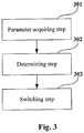
- Figure 3 is a flowchart of operating mode switching method between devices in near-field communication in a passive communication mode of embodiment 1 of the present invention. As shown in Fig. 3 , the method comprises:
- the switching of the operating mode refers to the one device being switched to the target mode to operate, and the other device being switched to the initiative mode to operate; and when the one device is a current target device, the switching of the operating mode refers to the current target device being switched to the initiative mode to operate, and the other device being switched to the target mode to operate.
- either one of the current initiator device and the current target device may determine whether to exchange operating mode with the other device according to the relevant parameters including the type of the device, so as to realize more reasonable distribution of power consumption between both devices in the near-field communication, reducing power consumption of the current initiator device.
- the one device may acquire the relevant parameters of the other device from the other device in any existing manner.
- the one device may transmit a parameter inquiry request to the other device; and the other device may return its relevant parameters to the one device through a parameter response message after receiving the parameter inquiry request, such that the one device acquires the relevant parameters of the other device.
- the type of the device may be included in the parameter inquiry request for transmission to the other device, such that the other device determines the relevant parameters provided to the one device according to the type of the parameters of the one device.
- the one device may acquire the relevant parameters of the other device from the other device at a predetermined time interval, namely, transmitting the parameter inquiry request to the other device at a predetermined time interval.
- the one device may also receive a switch inquiry message including the relevant parameters of the other device transmitted by the other device, so as to acquire the relevant parameters of the other device.
- the relevant parameters when one device and the other device are both mobile devices, the relevant parameters further include a duration time T1 of one device and a duration time T2 of the other device, wherein the duration time is also referred to as an endurance time.
- the duration time of the current initiator device is the value obtained by dividing the current energy supplied to the current initiator device by the real-time power consumption of the current initiator device; and when the other device is a current target device, the duration time of the current target device is the value obtained by dividing the current energy supplied to the current target device by the real-time power consumption of the current target device.
- the duration time may be obtained by any existing manner. Two of the manners will be described below.
- Step 302 will be described below taking that the one device is the current initiator device and the other device is the current target device as an example:
- Step 302 will be described below taking that the one device is the current target device and the other device is the current initiator device as an example:
- step 303 in case it is determined in step 302 that the one device exchanges operating mode with the other device, the exchange of the operating mode may be performed in the following steps when the one device is a current initiator device and exchanges operating mode with the other device:
- the one device When the one device is a current target device, the one device exchanges operating modes with the other device, comprising:
- either one of the current initiator device and the current target device may determine whether to exchange operating mode with the other device according to the types of the devices or the types of the devices and duration times, so as to realize more reasonable distribution of power consumption between both devices in the near-field communication, reducing power consumption of the current initiator device.
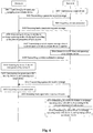
- Figure 4 is a flowchart of operating mode switch method between devices in near-field communication in a passive communication mode of embodiment 2 of the present invention.
- the description is provided taking the near-field communication in a passive communication mode between device A and device B as an example, wherein device A is a current initiator device and device B is a current target device.
- the relevant parameters of device B are obtained through transmitting by device A a parameter inquiry message to device B, the parameters comprising the type of device B.
- Device A is terminal equipment of a portable electronic device powered by a battery, such as a mobile phone.
- Device B is, for example, a smart card as a passive device, or a fixed device powered by commercial power.
- a fixed device that may be used as device B can be an automatic ticket issuing machine, ticket check gate, or an information booth, etc.
- the method comprises:
- step S409 in a case where device B transmits to device A the switch confirmation message in step S409, device A starts to perform step S410 after receiving the switch confirmation message; however, in a case where device B does not transmit to device A the switch confirmation message, device A may start to detect the RF field generated by device B after transmitting the switch request message; device A may be kept operating as a target device after the generation of RF field has been terminated in step S411; at this moment, device A is switched to a target device to operate and device B is switched to an initiator device to operate; in such a case, device B, as the current initiator device, may further determine whether to exchange operating mode with device A, comprising the steps of:
- device A when device A is a mobile device and device B is a passive device or a fixed device, after device A determines to exchange operating mode with device B, more reasonable distribution of power consumption between both devices in the near-field communication may be realized, reducing power consumption of the current initiator device, i.e. power consumption of the mobile device.
- device A is a mobile device and device B is a passive device or a fixed device as an example.
- Fig. 5 is a flowchart of operating mode switch method between devices in near-field communication in a passive communication mode of embodiment 3 of the present invention, wherein device B and device A are both mobile devices.
- steps S501 to S503 are similar to the corresponding steps of embodiment 2 shown in Fig. 4 , which shall not be described any further.
- the acquired relevant parameters comprise not only the type of device B, but also the duration time of device B.
- step S506 device A determines whether to exchange operating mode with device B according to the relevant parameters of both devices, comprising: acquiring the relevant parameters of its own by device A after obtaining the parameters of device B, the relevant parameters comprising the type of device, and duration time of device A; then determining by device A whether to exchange operating mode with device B according to the relevant parameters of both devices.
- device A determines whether the duration time of device B is greater than that of device A; and if the determining result is that the duration time of device B is greater than that of device A, device A determines to exchange operating mode with device B, that is to say, device A is switched to a target device to operate and device B is switched to an initiator device to operate.
- a first predetermined value is determined if the determining result is that the duration time of device B is greater than that of device A; and if the determining result is positive, it is determined that device A is switched to a target device to operate and device B is switched to an initiate device to operate; wherein the first predetermined value is configured as temporally required, which shall not be described any further.
- Steps S507 to S511 are similar to S407 to S411 of embodiment 2 shown in Fig. 4 , which shall not be described any further.
- the relevant parameters include not only the type of device, but also the duration time; thus, when the types of the devices are both mobile devices and the duration time of the current target device is greater than that of the current initiator device, the initiator device may determine to exchange operating mode with the target device, thereby the power consumption of the initiator device and the target device tending to equilibrium.
- the relationship between the duration times of devices A and B may change to a relatively large extent after a period of time. For example, since other applications consuming much power are suddenly added after device B is switched to a target device, the duration time of device B is shortened; or since other applications consuming much power in device A stop operating, the duration time of device A is extended. Therefore, it is preferable that device B, as a current initiator device, may transmit a parameter inquiry message at a certain time interval to device A, as a current target device, and perform the steps similar to steps S503 to S511, so as to determine whether to exchange operating mode with device A, as a current target device.
- step S512 similar to step S412 shown in Fig. 4 , device B may transmit to device A the parameter inquiry message with its type of device included.
- step S509 when device B transmits to device A the switch confirmation message, device A starts to perform step S510 after receiving the switch confirmation message.
- device A may detect the RF field generated by device B after receiving the switch confirmation message.
- devices A and B are both mobile devices
- device A determines to exchange operating mode with device B
- more reasonable power consumption distribution may be realized between both devices in near-field communication, reducing the power consumption of the current initiator device.
- the initiator device may proceed to determine whether to switch operating mode, further realizing the reasonable distribution of power consumption.
- device A as the initiator device, acquires the relevant parameters of device B from device B, as the target device; furthermore, device A may also acquire the relevant parameters of device B in the manner shown in Fig. 6 .
- Fig. 6 is a flowchart of operating mode switch method between devices in near-field communication in a passive communication mode of embodiment 4 of the present invention.
- steps S601 and S602 are similar to steps S401 and S402 shown in Fig. 4 , which shall not be described any further.
- step S603 device B, as the target device, first acquires its relevant parameters, for example, similar to embodiment 3, obtaining its type of device and duration time, and transmitting to device A a switch inquiry message with its relevant parameters included, such that device A acquires the relevant parameters of device B.
- device B as the target device, first acquires its relevant parameters, for example, similar to embodiment 3, obtaining its type of device and duration time, and transmitting to device A a switch inquiry message with its relevant parameters included, such that device A acquires the relevant parameters of device B.
- Step S605 is similar to step S506 shown in Fig. 5 , which shall not be described any further.
- step S606 determining in step S605 that device A is to be switched to the target mode to operate, device A transmits to device B the switch response message.
- Steps S607 to S610 are similar to steps S508 to S511 shown in Fig. 5 , which shall not be described any further.
- the initiator device determines whether to exchange operating mode as an example; in addition, the target device may also determine whether to exchange operating mode.
- Fig. 7 is a flowchart of operating mode switch method between devices in near-field communication in a passive communication mode of embodiment 5 of the present invention, wherein device A is used as the initiator device and device B is used as the target device.
- Steps S701 to S702 are similar to embodiment 2 and 3 shown in Fig. 4 and Fig.5 , which shall not be described any further.
- device B determines whether to exchange operating mode, comprising the steps of:
- This embodiment differs from embodiment 5 in that the manner for acquiring the parameters of device A is different.
- Fig. 8 is a flowchart of operating mode switch method between devices in near-field communication in a passive communication mode of embodiment 6 of the present invention, wherein device A operates as the initiator device and device B operates as the target device.
- Steps S801 to S802 are similar to embodiments 2 and 3 shown in Figs. 4 and 5 , which shall not be described any further.
- step S803 obtaining first by device A, as the initiator device, its relevant parameters, for example, obtaining its type of device, or its type of device and duration time;
- step S804 transmitting by device A the switch inquiry message to device B, including its relevant parameters, such that device B acquires the relevant parameters of device A;
- step S805 determining by device B whether to exchange operating mode with device A according to the relevant parameters of both devices; wherein the determining method is the same as that described above in embodiments 1-4, which shall not be described any further;
- step S806 generating by device B an RF field and switching to the initiative mode to operate as an initiator device if it is determined in step S805 that device B is to exchange operating mode with device A;
- step S807 transmitting by device B to device B the switch response message;
- step S808 detecting by device A the RF field generated by device B;
- step S809 terminating by device A the generation of the RF field and switching to the target mode to operate as a
- the initiator device may proceed to determine whether to exchange operating modes, so as to further realize reasonable power consumption distribution.
- step S506 device A acquires its relevant parameters in receiving the parameter response message fed back by device B; however, such relevant parameters may also be acquired after the near-field communication is established, instead of being acquired after the parameter response message of device B is received.
- the step of acquiring the relevant parameters of device A may be performed after the near-field communication is established and before the parameter inquiry message is transmitted.
- device A may be terminal equipment of a portable electronic device powered by a battery, such as a mobile phone.
- Device B may be, for example, a smart card as a passive device, a mobile device of a portable electronic device in the form of a mobile phone powered by a battery, or a fixed device powered by commercial power.
- a fixed device that may be used as device B can be an automatic ticket issuing machine, ticket check gate, or an information booth, etc.
- the embodiments of the present invention further provide an operating mode switch module and terminal equipment as described below.
- the principles for the operating mode switch module and terminal equipment in solving the technical problems are similar to the near-field communication method as described in above embodiments 1-6, the implementation of the operating mode switch module and terminal equipment may refer to the implementation of the method, which shall not be described any further.
- Fig. 9 is a schematic diagram of the structure of the operating mode switch module of embodiment 7 of the present invention.
- the operating mode switch module comprises: a parameter acquiring unit 901, a determining unit 902 and a switching unit 903, wherein the parameter acquiring unit 901 is used to acquire the relevant parameters containing the type of the device of the other device in near-field communication with the device where the operating mode switch module is present; the determining unit 902 is used to determine whether to exchange operating modes with the other device according to the relevant parameters of the device where the operating mode switch module is present and the relevant parameters of the other device acquired by the parameter acquiring unit 901; wherein the relevant parameters of the device where the operating mode switch module is present include type of the device; and the switching unit 903 is used to exchange the operating mode of the device where the operating mode switch module is present with the other device, if the determining result of the determining unit 902 is positive, such that the device where the operating mode switch module is present performs near-field communication with the other device in the exchanged operating
- the switching of operating mode refers to that the device where the operating mode switch module is present is switched to a target mode to operate and the other device is switched to an initiative mode to operate; and when the device where the operating mode switch module is present is a current target device, the switching of operating mode refers to that the device where the operating mode switch module is present is switched to an initiative mode to operate and the other device is switched to a target mode to operate.
- either one of the current initiator device and the current target device where the operating mode switch module is present can determine whether to exchange operating mode with the other device according to the relevant parameters including the type of device, so as to realize more reasonable distribution of power consumption between both devices in the near-field communication, reducing power consumption of the current initiator device.
- the manner for the parameter acquiring unit 901 to acquire the relevant parameters is the same as the two manners described in embodiments 1-6, which shall not be described any further.
- the operating mode switch module is referred to as operating mode switch module A when the device where the operating mode switch module is present is a current initiator device
- the operating mode switch module is referred to as operating mode switch module B when the device where the operating mode switch module are present is a current target device .
- the determining unit 902 of the operating mode switch module A may be used in the following cases; however, these cases are just embodiments of the present invention and the present invention are not limited thereto, and other manners may also be adopted for determination:
- the determining unit 902 comprises the following units (not shown):
- the determining unit 902 comprises the following units (not shown):
- its switching unit 903 may comprise:
- the switching unit 903 may optionally comprise a response message receiving unit (not shown) to receive the response message transmitted by the other device, and the detecting unit1002 may detect an RF field after the response message receiving unit receives the response message.
- the determining unit 902 of the operating mode switch module B may be used in the following cases; however, these cases are just embodiments of the present invention and the present invention is not limited thereto, and other manners may also be used for determination:
- its switching unit 903 may comprise:
- either the operating mode switch module A or the operating mode switch module B may further comprise a calculating unit (not shown) to calculate the duration time of the device where the operating mode switch module is present in a manner as described in embodiment 1, which shall not be described any further.
- the type of device may be obtained from the storing unit of the device where the operating mode switch module is present.
- the operating mode switch module may be arranged in different devices, that is to say, the device comprising the operating mode switch module A may be an initiator device, and the device comprising the operating mode switch module B may be a target device, such that the initiator device and the target device in near-field communication exchange operating mode realize more reasonable power consumption distribution in both parties in near-field communication and reducing the power consumption of the current initiator device.
- Fig. 12 is a schematic diagram of the structure of the terminal equipment containing an operating mode switch module of embodiment 8 of the present invention, wherein the terminal equipment comprises the operating mode switch module A as described in embodiment 7.
- the terminal equipment is a mobile phone, and this figure is exemplary only; the mobile phone 1200 may further have other types of circuit parts to supplement or replace this operational circuit, so as to realize the communication function or other functions. It is obvious that the mobile phone 1200 shown in Fig. 12 illustrates more parts than may be necessary to practice the invention, for example, the camera 1206 may be excluded.
- the mobile phone 1200 comprises a main control circuit 1201, a transceiver 1202, an input unit 1203, an audio processing unit 1204, a memory 1205, a camera 1206, a display 1207, a power supply 1208, a coulometer 1209 and a operating mode switch module A.
- the main control circuit 1201 is sometimes referred to as a controller or an operational control, which may comprise a microprocessor or other processing devices and/or logic devices, and receive input and control the operations of every components of the mobile phone 1200.
- the input unit 1203 provides multiple user input operations.
- the input unit 1203 generally comprises alphanumeric keys to allow for input of alphanumeric information, such a telephone number, a telephone number list, information on contact, and remarks, etc.
- the input unit 1203 may comprise specific functional keys, such as a "call transmit" key to initiate a call or respond a call, a "call end” key to end or “hang up” a call, and a channel recommendation key, etc.
- the input unit 1203 may be a touch screen.
- the function of a key or functions similar to the function of a key may be implemented as a touch screen related to the display 1207.
- the camera 1206 is used to capture image data.
- the image data captured by the camera 1206 is supplied to the main control circuit 1201 for use in a conventional way, such as for storage, and for transmission, etc.
- the display 1207 may be for example an LCD display, but it is not limited thereto. As usual, the display 1207 displays information to a user, such as an operating state, time, a phone number, information on a contact, and navigation menus, etc., so that the user can use all the functions of the telephone 1200. The display 1207 may also be visually display the contents received from the mobile phone 1200 and/or the contents taken from the memory 1205 of the mobile phone 1200.
- the mobile phone 1200 comprises an antenna 1211 coupled to the transceiver 1202.
- the transceiver 1202 comprises an RF transmitter and receiver to transmit and receive signals through the antenna 1211.
- the transceiver 1202 may be configured to operate in such mobile communication systems as GSM, CDMA, and WCDMA, etc., and receives audio contents.
- the receiver may be an IP data broadcasting compatible receiver, which is compatible with a mixed network structure providing mobile communication and services based on DVB-H or similar services.
- the transceiver 1202 is also coupled to a loudspeaker 1204-2 and a microphone 1204-1 via the audio processing unit 1204, so as to provide audio output via the loudspeaker 1204-2 and receive audio input from the microphone 1204-1.
- the audio processing unit 1204 may also comprise any appropriate buffers, decoders, and amplifiers, etc.
- the audio processing unit 1204 may be coupled to the main control circuit 1201, thereby enabling recording in the mobile phone 1 via the microphone 1204-1, that is, enabling the audio signals stored in the memory 1205 to be played via the loudspeaker 1204-2.
- the memory 1205 may be one or more of a buffer, a flash memory, a hard drive, a mobile medium, a volatile memory, a nonvolatile memory, or other appropriate devices.
- the memory 1205 comprises: a buffer cache to buffer data; an application/function storing portion to store applications and function programs or to store the operational flows to be executed by the main control circuit 1201; a data storing portion to store the data indicative of the type of the mobile phone, here, the code of the mobile device, and furthermore, to store the numerical values of the current energy, real-time power consumption of the mobile phone 1200, and contact, digital data, pictures, voices and/or other data used by the mobile phone 1200; and a driver storing portion to store the drivers of all the components of the mobile phone 1200, such as the drivers of the operating mode switch module A.
- the power supply 1208 is used to supply power to the mobile phone 1, and the coulometer 1209 is used to measure the current energy of the power supply 1208.
- the coulometer 1209 may be an amperemeter, which may be two, one for measuring the current total power of the battery, and the other for measuring the operating current of all the components including the operating mode switch module A of the mobile phone 1200; and then the two measured current values are compared to obtain the duration time of the mobile phone 1200.
- the coulometer 1209 may comprise two coulometers, one for measuring the current energy of the battery of the mobile phone 1200, and the other for detecting the energy at the current instant and at the next instant; in such a case, the duration time is the ratio of the current energy of the battery detected by the coulometer to the amount of change of the energy between the current instant and the next instant.
- the precision of the coulometer for measuring the current energy of the battery of the mobile phone may be lower than that of the coulometer for measuring the power at a certain instant.
- the operating mode switch module A may further comprise a calculating unit to calculate the duration time.
- the operating mode switch module A is an operating mode switch module disposed within the initiator device, that is to say, the mobile phone 1200 is the initiator device, and the operating mode switch module A is used to establish near-field communication with the operating mode switch module B in device B as the target device and may determine whether to exchange operating mode with device B after the near-field communication is established.
- the structure and communication manner of the operating mode switch module A are as described in embodiments 1-4, which shall not be described any further.
- the operating mode switch module A may determine the duration time of the mobile phone 1200 based on the current energy and real-time power consumption measured by the coulometer 1209 and read the code representative of the type of the mobile phone 1200 from the data storing portion in the memory 1205 in the mobile phone 1200.
- the calculating unit in the operating mode switch module A may calculate the duration time of the mobile phone 1200 by dividing the current power measured by the coulometer 1209 by the real-time power consumption of the device A.
- All the components in the mobile phone 1200 may be implemented by specific hardware, firmware, software, or a combination thereof, without departing from the scope of the present invention.
- Terminal equipment may be provided in embodiment 9.
- the equipment 1300 and respective components 1301-1309 and 1311 may comprise all the components 1201-1209 and 1211, respectively, shown in Fig. 12 , with the exception that the operating mode switch module A is replaced by the operating mode switch module B, such that the device containing the operating mode switch module B is used as the target device.
- the structure and communication manner of the operating mode switch module B are as described in embodiments 5-7, which shall not be described any further.
- the functions of all the components of the target device and the function of the operating mode switch module B are as described in the above embodiments, which shall not be described any further.
- terminal equipment may be provided in another embodiment of the present invention, which comprises the operating mode switch module A and the operating mode switch module B at the same time.
- the terminal equipment may correspond respectively to the initiator device and the target device, and the structures and communication manners of the switch modules for operating mode are as described in embodiments 8 and 9, which shall not be described any further.
- either one of the current initiator device and the current target device containing the operating mode switch module may determine whether to exchange operating mode with the other device according to the relevant parameters including the type of device, so as to realize more reasonable power consumption distribution in both parties in near-field communication and reduce the power consumption of the current initiator device.
- both devices in near-field communication generate an RF field; however, one of the devices may determine whether to switch to the target mode to operate according to the relevant parameters of both devices including the type of device, or further including the duration time; and if the determining result is that it can be switched to the target mode to operate, the power consumption of this device may be reduced.
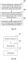
- Fig. 14 is a flowchart of operating mode switch method between devices in near-field communication in an active communication mode of embodiment 10 of the present invention. As shown in Fig. 14 , the method comprises:
- both of the devices in near-field communication generate an RF field; however, one of the devices may determine whether to switch to the target mode to operate according to the relevant parameters of both devices including type of the device, and if the determining result is that it can be switched to the target mode to operate, the power consumption of this device may be reduced.
- step S1401 is implemented as described in the above embodiment, which shall not be described any further.
- the determining step S1402 may include the following cases:
- the one device further determines whether the duration time of the other device is greater than the duration time of the one device when the one device determines according to the relevant parameters that the types of the one device and the other device are both mobile devices; and if the determining result is positive, the one device determines to switch to the target mode to operate.
- whether the difference between the duration times is greater than a predetermined value may further be determined before determining to switch to the target mode to operate; if the difference is greater than the predetermined value, it is determined to switch to the target mode to operate.
- switching the operation mode to the target mode refers to switching one of the both devices in an active mode to the target mode to operate, that is to say, this device stops generating an RF field, thereby reducing the power consumption of this device.
- Fig. 15 is a schematic diagram of the structure of the operating mode switch module of embodiment 11 of the present invention. As shown in Fig. 15 , the operating mode switch module comprises:
- both of the devices in near-field communication generate an RF field; however, one of the devices determines whether to switch to the target mode to operate according to the relevant parameters of both devices including type of the device, and if the determining result is that it can be switched to the target mode to operate, the power consumption of this device may be reduced.
- the determining unit 1502 is used to determine that the device where the operating mode switch module is present is to be switched to the target mode to operate when the type of the device where the operating mode switch module is present is a mobile device and the type of the other device is a fixed device.
- the determining unit 1502 is used to determine that the device where the operating mode switch module is present is not to be switched to the target mode to operate when the type of the device where the operating mode switch module is present is a fixed device and the type of the other device is a mobile device.
- the relevant parameters include the duration time of the one device and the duration time of the other device.
- the determining unit 1502 is used to determine that the device where the operating mode switch module is present is to be switched to the target mode to operate when the types of the device where the operating mode switch module is present and the other device are both mobile devices and the duration time of the other device is greater than the duration time of the device where the operating mode switch module is present.
- whether the difference between the duration times is greater than a predetermined value may further be determined before it is determined by the determining unit 1502 to switch to the target mode to operate; if the difference is greater than the predetermined value, it is determined to switch to the target mode to operate.
- switching the operation mode to the target mode by the switching unit 1503 refers to switching one of the both devices in an active mode to the target mode to operate, that is to say, this device stops generating an RF field, thereby reducing the power consumption of this device.
- Fig. 16 is a schematic block diagram of the operational circuit or system structure of the terminal equipment of embodiment 12 of the present invention.
- the terminal equipment 1600 comprises the operating mode switch module C , of which the structure and function are similar to that of the above embodiment, which shall not be described any further; and other components 1601-1609 and 1611 are similar to those shown in Figs. 12 and 13 (designated by corresponding reference numerals 1201-1209 and 1211 and by corresponding reference numerals 1311-1309 and 1311, respectively), with the functions of the identical parts being identical to those shown in Figs. 12 and 13 , which shall not be described any further.
- one of the devices in near-field communication may determine whether to switch to the target mode to operate according to the relevant parameters of both devices in near-field communication including the type of device, or further including the duration times of both devices, or may determine whether to exchange operating mode with other device, thereby realizing more reasonable power consumption distribution in both devices in near-field communication.
- the above devices and methods of the present invention may be implemented by hardware, and may also be implemented by hardware in combination with software.
- the present invention relates to such a computer-readable program that when the program is executed by a logic part, it enables the logic part to realized the above-described devices or components, or enables the logic part to realize all the methods and steps as described above.
- the present invention relates also to a storage medium storing the above program, such as a hard disc, a floppy disc, a compacted disc, a DVD, and a flash memory, etc.
Landscapes
- Engineering & Computer Science (AREA)
- Computer Networks & Wireless Communication (AREA)
- Signal Processing (AREA)
- Human Computer Interaction (AREA)
- Telephone Function (AREA)
- Mobile Radio Communication Systems (AREA)
Claims (11)
- Verfahren zum Umschalten eines Betriebsmodus zwischen Nahfeldkommunikationsvorrichtungen, wobei das Verfahren die folgenden Schritte umfasst:einen Parametererfassungsschritt (301, 1401): Erfassen, durch eine Vorrichtung von zwei Vorrichtungen in Nahfeldkommunikation, von relevanten Parametern der einen Vorrichtung und der anderen Vorrichtung, die Art der anderen Vorrichtung, eine verbleibende Batteriedauer der einen Vorrichtung und eine verbleibende Batteriedauer der anderen Vorrichtung beinhalten;einen Bestimmungsschritt (302, 1402): Bestimmen, durch die eine Vorrichtung, ob gemäß den relevanten Parametern der einen Vorrichtung und der anderen Vorrichtung in einen Ziel-Betriebsmodus umgeschaltet werden soll, wobei die relevanten Parameter der einen Vorrichtung die Art der einen Vorrichtung beinhalten, und Bestimmen, ob die verbleibende Batteriedauer der anderen Vorrichtung größer als die verbleibende Batteriedauer der einen Vorrichtung ist; undeinen Umschaltschritt (303, 1403): Umschalten des Betriebsmodus durch die eine Vorrichtung in den Zielmodus, wenn die Bestimmungsergebnisse des Bestimmungsschritts positiv sind.
- Verfahren nach Anspruch 1, wobei
das Bestimmen, durch die eine Vorrichtung, ob gemäß den relevanten Parametern der einen Vorrichtung und der anderen Vorrichtung in einen Ziel-Betriebsmodus umgeschaltet werden soll, Folgendes umfasst:
Bestimmen, durch die eine Vorrichtung, ob sowohl die Art der einen Vorrichtung als auch die Art der anderen Vorrichtung eine Mobilvorrichtung ist. - Verfahren nach Anspruch 2, wobei die eine Vorrichtung eine aktuelle Initiatorvorrichtung ist und die andere Vorrichtung eine aktuelle Zielvorrichtung ist, und
wobei die verbleibende Batteriedauer der aktuellen Initiatorvorrichtung (101, 201) ein Wert ist, der durch Dividieren einer der einen Vorrichtung (101, 201) zugeführten aktuellen Energie durch eine Echtzeitleistungsaufnahme der aktuellen Initiatorvorrichtung (101, 201) erhalten wird; und
die verbleibende Batteriedauer der aktuellen Zielvorrichtung (102, 202) ein Wert ist, der durch Dividieren einer der aktuellen Zielvorrichtung (102, 202) zugeführten aktuellen Energie durch eine Echtzeitleistungsaufnahme der aktuellen Zielvorrichtung (102, 202) erhalten wird. - Verfahren nach Anspruch 1, wobei der Parametererfassungsschritt Folgendes umfasst: Empfangen, durch die eine Vorrichtung, einer Umschaltanfragenachricht, die die durch die andere Vorrichtung übertragenen relevanten Parameter der anderen Vorrichtung enthält, um die relevanten Parameter der anderen Vorrichtung zu erfassen; wobei die relevanten Parameter die Art und die verbleibende Batteriedauer der anderen Vorrichtung umfassen.
- Verfahren zum Umschalten eines Betriebsmodus zwischen Nahfeldkommunikationsvorrichtungen, wobei das Verfahren die folgenden Schritte umfasst:einen Parametererfassungsschritt (301, 1401): Erfassen, durch eine Vorrichtung von zwei Vorrichtungen in Nahfeldkommunikation, von relevanten Parametern der einen Vorrichtung und der anderen Vorrichtung, die Art der anderen Vorrichtung, eine verbleibende Batteriedauer der einen Vorrichtung und eine verbleibende Batteriedauer der anderen Vorrichtung beinhalten;einen Bestimmungsschritt (302, 1402): Bestimmen, durch die eine Vorrichtung, ob gemäß den relevanten Parametern der einen Vorrichtung und der anderen Vorrichtung Betriebsmodi getauscht werden sollen, wobei die relevanten Parameter der einen Vorrichtung die Art der einen Vorrichtung beinhalten, und Bestimmen, ob die verbleibende Batteriedauer der anderen Vorrichtung größer als die verbleibende Batteriedauer der einen Vorrichtung ist; undeinen Umschaltschritt (303, 1403): Tauschen des Betriebsmodus der einen Vorrichtung mit dem der anderen Vorrichtung, wenn die Bestimmungsergebnisse des Bestimmungsschritts positiv sind.
- Verfahren nach Anspruch 5, wobei die eine Vorrichtung eine aktuelle Initiatorvorrichtung (101, 201) ist und die andere Vorrichtung eine aktuelle Zielvorrichtung (102, 202) ist; und
wobei das Bestimmen, durch die eine Vorrichtung, ob gemäß den relevanten Parametern der einen Vorrichtung und der anderen Vorrichtung Betriebsmodi getauscht werden sollen, Folgendes umfasst: Bestimmen, durch die eine Vorrichtung, ob sowohl die Art der einen Vorrichtung als auch die Art der anderen Vorrichtung eine Mobilvorrichtung ist. - Verfahren nach Anspruch 5, wobei der Parametererfassungsschritt Folgendes umfasst: Empfangen, durch die eine Vorrichtung, einer Umschaltanfragenachricht, die die durch die andere Vorrichtung übertragenen relevanten Parameter der anderen Vorrichtung enthält, um die relevanten Parameter der anderen Vorrichtung zu erfassen; wobei die relevanten Parameter die Art und die verbleibende Batteriedauer der anderen Vorrichtung umfassen.
- Verfahren nach Anspruch 5, wobei, wenn die eine Vorrichtung eine aktuelle Initiatorvorrichtung (101, 201) ist, die eine Vorrichtung Betriebsmodi mit der anderen Vorrichtung tauscht, umfassend:Übertragen, durch die eine Vorrichtung an die andere Vorrichtung, einer Umschaltanfragenachricht, die die andere Vorrichtung anweist, zum Betrieb in den Zielmodus umzuschalten, so dass die andere Vorrichtung ein HF-Feld erzeugt und zum Betrieb in den Initiativmodus umschaltet;Detektieren (S410, S510, S609, S709, S809) des durch die andere Vorrichtung erzeugten HF-Felds; undBeenden (S411, S511, S610, S710, S810) durch die eine Vorrichtung der Erzeugung des HF-Felds und Umschalten zum Betrieb in den Zielmodus, wenn das durch die andere Vorrichtung erzeugte HF-Feld detektiert wird.
- Verfahren nach Anspruch 5, wobei, wenn die eine Vorrichtung eine aktuelle Zielvorrichtung (102, 202) ist, die eine Vorrichtung Betriebsmodi mit der anderen Vorrichtung tauscht, umfassend:Erzeugen (S408, S508, S517, S607) eines HF-Felds durch die eine Vorrichtung und Umschalten in den Initiativmodus zum Betrieb; undInformieren (S409, S509, S518, S608) der anderen Vorrichtung, so dass die andere Vorrichtung die Erzeugung des HF-Felds beendet und zum Betrieb in den Zielmodus umschaltet, wenn die andere Vorrichtung das durch die eine Vorrichtung erzeugte HF-Feld detektiert.
- Modul zum Umschalten eines Betriebsmodus zwischen Nahfeldkommunikationsvorrichtungen, wobei das Modul in einer Vorrichtung von zwei Vorrichtungen in Nahfeldkommunikation angeordnet ist und wobei das Modul Folgendes umfasst:eine Parametererfassungseinheit (901, 1501), ausgelegt zum Erfassen von relevanten Parametern der einen Vorrichtung und der anderen Vorrichtung, die Art der anderen Vorrichtung, eine verbleibende Batteriedauer der einen Vorrichtung und eine verbleibende Batteriedauer der anderen Vorrichtung beinhalten;eine Bestimmungseinheit (902, 1502), ausgelegt zum Bestimmen, ob gemäß den relevanten Parametern der einen Vorrichtung und der anderen Vorrichtung in einen Ziel-Betriebsmodus umgeschaltet werden soll; wobei die relevanten Parameter der einen Vorrichtung die Art der einen Vorrichtung beinhalten; und die Bestimmungseinheit ferner ausgelegt ist zum Bestimmen, ob die verbleibende Batteriedauer der anderen Vorrichtung größer als die verbleibende Batteriedauer der einen Vorrichtung ist; undeine Umschalteinheit (903, 1503), ausgelegt zum Umschalten des Betriebsmodus der einen Vorrichtung in den Zielmodus, wenn die Bestimmungsergebnisse der Bestimmungseinheit positiv sind.
- Modul zum Umschalten eines Betriebsmodus zwischen Nahfeldkommunikationsvorrichtungen, wobei das Modul in einer Vorrichtung von zwei Vorrichtungen in Nahfeldkommunikation angeordnet ist und wobei das Modul Folgendes umfasst:eine Parametererfassungseinheit (901, 1501), ausgelegt zum Erfassen von relevanten Parametern der einen Vorrichtung und der anderen Vorrichtung, die Art der anderen Vorrichtung, eine verbleibende Batteriedauer der einen Vorrichtung und eine verbleibende Batteriedauer der anderen Vorrichtung beinhalten;eine Bestimmungseinheit (902, 1502), ausgelegt zum Bestimmen, ob gemäß den relevanten Parametern der einen Vorrichtung und der anderen Vorrichtung Betriebsmodi mit der anderen getauscht werden sollen; wobei die relevanten Parameter der einen Vorrichtung die Art der einen Vorrichtung beinhalten; und die Bestimmungseinheit ferner ausgelegt ist zum Bestimmen, ob die verbleibende Batteriedauer der anderen Vorrichtung größer als die verbleibende Batteriedauer der einen Vorrichtung ist; undeine Umschalteinheit (903, 1503), ausgelegt zum Tauschen des Betriebsmodus der einen Vorrichtung mit dem der anderen Vorrichtung, wenn die Bestimmungsergebnisse der Bestimmungseinheit positiv sind.
Applications Claiming Priority (2)
| Application Number | Priority Date | Filing Date | Title |
|---|---|---|---|
| CN2011100760538A CN102710296A (zh) | 2011-03-28 | 2011-03-28 | 工作模式切换方法、工作模式切换模块和终端设备 |
| US13/428,783 US20120252363A1 (en) | 2011-03-28 | 2012-03-23 | Method and module for switching operating mode, and terminal equipment |
Publications (3)
| Publication Number | Publication Date |
|---|---|
| EP2506448A2 EP2506448A2 (de) | 2012-10-03 |
| EP2506448A3 EP2506448A3 (de) | 2017-10-25 |
| EP2506448B1 true EP2506448B1 (de) | 2021-08-04 |
Family
ID=45874733
Family Applications (1)
| Application Number | Title | Priority Date | Filing Date |
|---|---|---|---|
| EP12161301.2A Active EP2506448B1 (de) | 2011-03-28 | 2012-03-26 | Verfahren und Modul zum Schalten des Betriebsmodus und Endgerätausrüstung |
Country Status (1)
| Country | Link |
|---|---|
| EP (1) | EP2506448B1 (de) |
Families Citing this family (4)
| Publication number | Priority date | Publication date | Assignee | Title |
|---|---|---|---|---|
| JP5969775B2 (ja) * | 2012-03-05 | 2016-08-17 | キヤノン株式会社 | 情報処理装置、制御方法、およびプログラム |
| CN104219386B (zh) * | 2014-08-28 | 2018-04-27 | 深圳市金立通信设备有限公司 | 一种终端 |
| CN104219387B (zh) * | 2014-08-28 | 2018-04-27 | 深圳市金立通信设备有限公司 | 一种情景模式的自动切换方法 |
| CN120021297A (zh) * | 2023-11-20 | 2025-05-20 | 维沃移动通信有限公司 | 信息处理方法、装置、通信设备及可读存储介质 |
Family Cites Families (6)
| Publication number | Priority date | Publication date | Assignee | Title |
|---|---|---|---|---|
| JP3951298B2 (ja) * | 2002-12-17 | 2007-08-01 | ソニー株式会社 | 通信装置および通信方法 |
| JP4023308B2 (ja) * | 2002-12-17 | 2007-12-19 | ソニー株式会社 | 通信装置および通信方法 |
| EP1653632B1 (de) * | 2004-10-29 | 2014-12-17 | Sony Deutschland GmbH | Verfahren zum Betrieb eines Nahfeld-Kommunikationssystems |
| GB0507285D0 (en) * | 2005-04-11 | 2005-05-18 | Innovision Res & Tech Plc | Nfc enabled high-speed data |
| JP4684888B2 (ja) * | 2005-12-28 | 2011-05-18 | キヤノン株式会社 | 通信装置及び電力制御方法 |
| JP2010130311A (ja) * | 2008-11-27 | 2010-06-10 | Sony Corp | 通信装置、通信方法、プログラム、および通信システム |
-
2012
- 2012-03-26 EP EP12161301.2A patent/EP2506448B1/de active Active
Non-Patent Citations (1)
| Title |
|---|
| None * |
Also Published As
| Publication number | Publication date |
|---|---|
| EP2506448A3 (de) | 2017-10-25 |
| EP2506448A2 (de) | 2012-10-03 |
Similar Documents
| Publication | Publication Date | Title |
|---|---|---|
| US20120252363A1 (en) | Method and module for switching operating mode, and terminal equipment | |
| JP5645438B2 (ja) | 給電装置及び給電方法 | |
| US9697725B2 (en) | Apparatus and method for providing battery information, and user terminal therefor | |
| US20110001457A1 (en) | Battery charge status indicator for user terminal device | |
| US8335870B2 (en) | Method of controlling mobile terminal on external device basis and external device operating system using the same | |
| US11968665B2 (en) | Resource configuration methods and apparatuses | |
| US11646856B2 (en) | Timing configuration method and apparatus | |
| RU2634750C2 (ru) | Схема сопряжения, способ и устройство для переключения состояний | |
| US12167433B2 (en) | Methods and apparatuses for configuring sidelink resource | |
| KR20120138311A (ko) | 휴대 단말기에서 배터리를 교체하는 장치 및 방법 | |
| CN105407473A (zh) | 无线局域网发现方法及装置 | |
| JP6061620B2 (ja) | 電子機器、制御方法及びコンピュータプログラム | |
| CN114898760A (zh) | 语音编码方法、装置、电子设备及存储介质 | |
| EP2506448A2 (de) | Verfahren und Modul zum Schalten des Betriebsmodus und Endgerätausrüstung | |
| JP2015109749A (ja) | 通信装置、通信装置の制御方法、プログラム | |
| CN105262512A (zh) | 切换主机的方法及装置 | |
| US11917562B2 (en) | Vehicle-to-everything synchronization method and device | |
| EP2587617A2 (de) | Vorrichtung und Verfahren zur Steuerung des Ladestroms in einem tragbaren Endgerät | |
| CN104967174A (zh) | 充电控制方法及装置 | |
| CN114362326A (zh) | 充放电系统、方法、装置、终端设备及存储介质 | |
| US8935324B2 (en) | Apparatus and method for providing instant messaging and presence service in mobile communication system | |
| KR20150042066A (ko) | 부팅 운용 방법 및 그 전자 장치 | |
| EP4037127A1 (de) | Verfahren und vorrichtung zum laden, endgerät und speichermedium | |
| CN104917238A (zh) | 控制设备供电的方法、装置及智能设备 | |
| CN103985895A (zh) | 电池控制方法、装置及终端 |
Legal Events
| Date | Code | Title | Description |
|---|---|---|---|
| PUAI | Public reference made under article 153(3) epc to a published international application that has entered the european phase |
Free format text: ORIGINAL CODE: 0009012 |
|
| AK | Designated contracting states |
Kind code of ref document: A2 Designated state(s): AL AT BE BG CH CY CZ DE DK EE ES FI FR GB GR HR HU IE IS IT LI LT LU LV MC MK MT NL NO PL PT RO RS SE SI SK SM TR |
|
| AX | Request for extension of the european patent |
Extension state: BA ME |
|
| RIC1 | Information provided on ipc code assigned before grant |
Ipc: H04W 52/02 20090101ALI20170504BHEP Ipc: H04B 5/00 20060101AFI20170504BHEP |
|
| PUAL | Search report despatched |
Free format text: ORIGINAL CODE: 0009013 |
|
| AK | Designated contracting states |
Kind code of ref document: A3 Designated state(s): AL AT BE BG CH CY CZ DE DK EE ES FI FR GB GR HR HU IE IS IT LI LT LU LV MC MK MT NL NO PL PT RO RS SE SI SK SM TR |
|
| AX | Request for extension of the european patent |
Extension state: BA ME |
|
| RIC1 | Information provided on ipc code assigned before grant |
Ipc: H04W 52/02 20090101ALI20170918BHEP Ipc: H04B 5/00 20060101AFI20170918BHEP |
|
| STAA | Information on the status of an ep patent application or granted ep patent |
Free format text: STATUS: REQUEST FOR EXAMINATION WAS MADE |
|
| 17P | Request for examination filed |
Effective date: 20180328 |
|
| RBV | Designated contracting states (corrected) |
Designated state(s): AL AT BE BG CH CY CZ DE DK EE ES FI FR GB GR HR HU IE IS IT LI LT LU LV MC MK MT NL NO PL PT RO RS SE SI SK SM TR |
|
| STAA | Information on the status of an ep patent application or granted ep patent |
Free format text: STATUS: EXAMINATION IS IN PROGRESS |
|
| 17Q | First examination report despatched |
Effective date: 20180829 |
|
| GRAP | Despatch of communication of intention to grant a patent |
Free format text: ORIGINAL CODE: EPIDOSNIGR1 |
|
| STAA | Information on the status of an ep patent application or granted ep patent |
Free format text: STATUS: GRANT OF PATENT IS INTENDED |
|
| INTG | Intention to grant announced |
Effective date: 20210311 |
|
| GRAS | Grant fee paid |
Free format text: ORIGINAL CODE: EPIDOSNIGR3 |
|
| GRAA | (expected) grant |
Free format text: ORIGINAL CODE: 0009210 |
|
| STAA | Information on the status of an ep patent application or granted ep patent |
Free format text: STATUS: THE PATENT HAS BEEN GRANTED |
|
| AK | Designated contracting states |
Kind code of ref document: B1 Designated state(s): AL AT BE BG CH CY CZ DE DK EE ES FI FR GB GR HR HU IE IS IT LI LT LU LV MC MK MT NL NO PL PT RO RS SE SI SK SM TR |
|
| RAP1 | Party data changed (applicant data changed or rights of an application transferred) |
Owner name: SONY GROUP CORPORATION |
|
| REG | Reference to a national code |
Ref country code: GB Ref legal event code: FG4D |
|
| REG | Reference to a national code |
Ref country code: AT Ref legal event code: REF Ref document number: 1418056 Country of ref document: AT Kind code of ref document: T Effective date: 20210815 |
|
| REG | Reference to a national code |
Ref country code: CH Ref legal event code: EP |
|
| REG | Reference to a national code |
Ref country code: DE Ref legal event code: R096 Ref document number: 602012076270 Country of ref document: DE |
|
| REG | Reference to a national code |
Ref country code: NL Ref legal event code: FP Ref country code: IE Ref legal event code: FG4D |
|
| REG | Reference to a national code |
Ref country code: LT Ref legal event code: MG9D |
|
| REG | Reference to a national code |
Ref country code: AT Ref legal event code: MK05 Ref document number: 1418056 Country of ref document: AT Kind code of ref document: T Effective date: 20210804 |
|
| PG25 | Lapsed in a contracting state [announced via postgrant information from national office to epo] |
Ref country code: HR Free format text: LAPSE BECAUSE OF FAILURE TO SUBMIT A TRANSLATION OF THE DESCRIPTION OR TO PAY THE FEE WITHIN THE PRESCRIBED TIME-LIMIT Effective date: 20210804 Ref country code: SE Free format text: LAPSE BECAUSE OF FAILURE TO SUBMIT A TRANSLATION OF THE DESCRIPTION OR TO PAY THE FEE WITHIN THE PRESCRIBED TIME-LIMIT Effective date: 20210804 Ref country code: AT Free format text: LAPSE BECAUSE OF FAILURE TO SUBMIT A TRANSLATION OF THE DESCRIPTION OR TO PAY THE FEE WITHIN THE PRESCRIBED TIME-LIMIT Effective date: 20210804 Ref country code: BG Free format text: LAPSE BECAUSE OF FAILURE TO SUBMIT A TRANSLATION OF THE DESCRIPTION OR TO PAY THE FEE WITHIN THE PRESCRIBED TIME-LIMIT Effective date: 20211104 Ref country code: LT Free format text: LAPSE BECAUSE OF FAILURE TO SUBMIT A TRANSLATION OF THE DESCRIPTION OR TO PAY THE FEE WITHIN THE PRESCRIBED TIME-LIMIT Effective date: 20210804 Ref country code: RS Free format text: LAPSE BECAUSE OF FAILURE TO SUBMIT A TRANSLATION OF THE DESCRIPTION OR TO PAY THE FEE WITHIN THE PRESCRIBED TIME-LIMIT Effective date: 20210804 Ref country code: NO Free format text: LAPSE BECAUSE OF FAILURE TO SUBMIT A TRANSLATION OF THE DESCRIPTION OR TO PAY THE FEE WITHIN THE PRESCRIBED TIME-LIMIT Effective date: 20211104 Ref country code: PT Free format text: LAPSE BECAUSE OF FAILURE TO SUBMIT A TRANSLATION OF THE DESCRIPTION OR TO PAY THE FEE WITHIN THE PRESCRIBED TIME-LIMIT Effective date: 20211206 Ref country code: FI Free format text: LAPSE BECAUSE OF FAILURE TO SUBMIT A TRANSLATION OF THE DESCRIPTION OR TO PAY THE FEE WITHIN THE PRESCRIBED TIME-LIMIT Effective date: 20210804 Ref country code: ES Free format text: LAPSE BECAUSE OF FAILURE TO SUBMIT A TRANSLATION OF THE DESCRIPTION OR TO PAY THE FEE WITHIN THE PRESCRIBED TIME-LIMIT Effective date: 20210804 |
|
| PG25 | Lapsed in a contracting state [announced via postgrant information from national office to epo] |
Ref country code: PL Free format text: LAPSE BECAUSE OF FAILURE TO SUBMIT A TRANSLATION OF THE DESCRIPTION OR TO PAY THE FEE WITHIN THE PRESCRIBED TIME-LIMIT Effective date: 20210804 Ref country code: LV Free format text: LAPSE BECAUSE OF FAILURE TO SUBMIT A TRANSLATION OF THE DESCRIPTION OR TO PAY THE FEE WITHIN THE PRESCRIBED TIME-LIMIT Effective date: 20210804 Ref country code: GR Free format text: LAPSE BECAUSE OF FAILURE TO SUBMIT A TRANSLATION OF THE DESCRIPTION OR TO PAY THE FEE WITHIN THE PRESCRIBED TIME-LIMIT Effective date: 20211105 |
|
| PG25 | Lapsed in a contracting state [announced via postgrant information from national office to epo] |
Ref country code: DK Free format text: LAPSE BECAUSE OF FAILURE TO SUBMIT A TRANSLATION OF THE DESCRIPTION OR TO PAY THE FEE WITHIN THE PRESCRIBED TIME-LIMIT Effective date: 20210804 |
|
| PGFP | Annual fee paid to national office [announced via postgrant information from national office to epo] |
Ref country code: GB Payment date: 20220225 Year of fee payment: 11 Ref country code: DE Payment date: 20220217 Year of fee payment: 11 |
|
| REG | Reference to a national code |
Ref country code: DE Ref legal event code: R097 Ref document number: 602012076270 Country of ref document: DE |
|
| PG25 | Lapsed in a contracting state [announced via postgrant information from national office to epo] |
Ref country code: SM Free format text: LAPSE BECAUSE OF FAILURE TO SUBMIT A TRANSLATION OF THE DESCRIPTION OR TO PAY THE FEE WITHIN THE PRESCRIBED TIME-LIMIT Effective date: 20210804 Ref country code: SK Free format text: LAPSE BECAUSE OF FAILURE TO SUBMIT A TRANSLATION OF THE DESCRIPTION OR TO PAY THE FEE WITHIN THE PRESCRIBED TIME-LIMIT Effective date: 20210804 Ref country code: RO Free format text: LAPSE BECAUSE OF FAILURE TO SUBMIT A TRANSLATION OF THE DESCRIPTION OR TO PAY THE FEE WITHIN THE PRESCRIBED TIME-LIMIT Effective date: 20210804 Ref country code: EE Free format text: LAPSE BECAUSE OF FAILURE TO SUBMIT A TRANSLATION OF THE DESCRIPTION OR TO PAY THE FEE WITHIN THE PRESCRIBED TIME-LIMIT Effective date: 20210804 Ref country code: CZ Free format text: LAPSE BECAUSE OF FAILURE TO SUBMIT A TRANSLATION OF THE DESCRIPTION OR TO PAY THE FEE WITHIN THE PRESCRIBED TIME-LIMIT Effective date: 20210804 Ref country code: AL Free format text: LAPSE BECAUSE OF FAILURE TO SUBMIT A TRANSLATION OF THE DESCRIPTION OR TO PAY THE FEE WITHIN THE PRESCRIBED TIME-LIMIT Effective date: 20210804 |
|
| PGFP | Annual fee paid to national office [announced via postgrant information from national office to epo] |
Ref country code: NL Payment date: 20220217 Year of fee payment: 11 |
|
| PLBE | No opposition filed within time limit |
Free format text: ORIGINAL CODE: 0009261 |
|
| STAA | Information on the status of an ep patent application or granted ep patent |
Free format text: STATUS: NO OPPOSITION FILED WITHIN TIME LIMIT |
|
| 26N | No opposition filed |
Effective date: 20220506 |
|
| PG25 | Lapsed in a contracting state [announced via postgrant information from national office to epo] |
Ref country code: IT Free format text: LAPSE BECAUSE OF FAILURE TO SUBMIT A TRANSLATION OF THE DESCRIPTION OR TO PAY THE FEE WITHIN THE PRESCRIBED TIME-LIMIT Effective date: 20210804 |
|
| PG25 | Lapsed in a contracting state [announced via postgrant information from national office to epo] |
Ref country code: SI Free format text: LAPSE BECAUSE OF FAILURE TO SUBMIT A TRANSLATION OF THE DESCRIPTION OR TO PAY THE FEE WITHIN THE PRESCRIBED TIME-LIMIT Effective date: 20210804 |
|
| PG25 | Lapsed in a contracting state [announced via postgrant information from national office to epo] |
Ref country code: MC Free format text: LAPSE BECAUSE OF FAILURE TO SUBMIT A TRANSLATION OF THE DESCRIPTION OR TO PAY THE FEE WITHIN THE PRESCRIBED TIME-LIMIT Effective date: 20210804 |
|
| REG | Reference to a national code |
Ref country code: CH Ref legal event code: PL |
|
| REG | Reference to a national code |
Ref country code: BE Ref legal event code: MM Effective date: 20220331 |
|
| PG25 | Lapsed in a contracting state [announced via postgrant information from national office to epo] |
Ref country code: LU Free format text: LAPSE BECAUSE OF NON-PAYMENT OF DUE FEES Effective date: 20220326 Ref country code: LI Free format text: LAPSE BECAUSE OF NON-PAYMENT OF DUE FEES Effective date: 20220331 Ref country code: IE Free format text: LAPSE BECAUSE OF NON-PAYMENT OF DUE FEES Effective date: 20220326 Ref country code: FR Free format text: LAPSE BECAUSE OF NON-PAYMENT OF DUE FEES Effective date: 20220331 Ref country code: CH Free format text: LAPSE BECAUSE OF NON-PAYMENT OF DUE FEES Effective date: 20220331 |
|
| PG25 | Lapsed in a contracting state [announced via postgrant information from national office to epo] |
Ref country code: BE Free format text: LAPSE BECAUSE OF NON-PAYMENT OF DUE FEES Effective date: 20220331 |
|
| REG | Reference to a national code |
Ref country code: DE Ref legal event code: R119 Ref document number: 602012076270 Country of ref document: DE |
|
| REG | Reference to a national code |
Ref country code: NL Ref legal event code: MM Effective date: 20230401 |
|
| GBPC | Gb: european patent ceased through non-payment of renewal fee |
Effective date: 20230326 |
|
| PG25 | Lapsed in a contracting state [announced via postgrant information from national office to epo] |
Ref country code: NL Free format text: LAPSE BECAUSE OF NON-PAYMENT OF DUE FEES Effective date: 20230401 |
|
| PG25 | Lapsed in a contracting state [announced via postgrant information from national office to epo] |
Ref country code: GB Free format text: LAPSE BECAUSE OF NON-PAYMENT OF DUE FEES Effective date: 20230326 |
|
| PG25 | Lapsed in a contracting state [announced via postgrant information from national office to epo] |
Ref country code: GB Free format text: LAPSE BECAUSE OF NON-PAYMENT OF DUE FEES Effective date: 20230326 Ref country code: DE Free format text: LAPSE BECAUSE OF NON-PAYMENT OF DUE FEES Effective date: 20231003 |
|
| PG25 | Lapsed in a contracting state [announced via postgrant information from national office to epo] |
Ref country code: HU Free format text: LAPSE BECAUSE OF FAILURE TO SUBMIT A TRANSLATION OF THE DESCRIPTION OR TO PAY THE FEE WITHIN THE PRESCRIBED TIME-LIMIT; INVALID AB INITIO Effective date: 20120326 |
|
| PG25 | Lapsed in a contracting state [announced via postgrant information from national office to epo] |
Ref country code: MK Free format text: LAPSE BECAUSE OF FAILURE TO SUBMIT A TRANSLATION OF THE DESCRIPTION OR TO PAY THE FEE WITHIN THE PRESCRIBED TIME-LIMIT Effective date: 20210804 Ref country code: CY Free format text: LAPSE BECAUSE OF FAILURE TO SUBMIT A TRANSLATION OF THE DESCRIPTION OR TO PAY THE FEE WITHIN THE PRESCRIBED TIME-LIMIT Effective date: 20210804 |
|
| PG25 | Lapsed in a contracting state [announced via postgrant information from national office to epo] |
Ref country code: MT Free format text: LAPSE BECAUSE OF FAILURE TO SUBMIT A TRANSLATION OF THE DESCRIPTION OR TO PAY THE FEE WITHIN THE PRESCRIBED TIME-LIMIT Effective date: 20210804 |
|
| PG25 | Lapsed in a contracting state [announced via postgrant information from national office to epo] |
Ref country code: TR Free format text: LAPSE BECAUSE OF FAILURE TO SUBMIT A TRANSLATION OF THE DESCRIPTION OR TO PAY THE FEE WITHIN THE PRESCRIBED TIME-LIMIT Effective date: 20210804 |