EP2506573B1 - Dispositif d'affichage par projection et procédé d'affichage par projection - Google Patents
Dispositif d'affichage par projection et procédé d'affichage par projection Download PDFInfo
- Publication number
- EP2506573B1 EP2506573B1 EP12161632.0A EP12161632A EP2506573B1 EP 2506573 B1 EP2506573 B1 EP 2506573B1 EP 12161632 A EP12161632 A EP 12161632A EP 2506573 B1 EP2506573 B1 EP 2506573B1
- Authority
- EP
- European Patent Office
- Prior art keywords
- light
- light emitting
- emitting elements
- unit
- semiconductor light
- Prior art date
- Legal status (The legal status is an assumption and is not a legal conclusion. Google has not performed a legal analysis and makes no representation as to the accuracy of the status listed.)
- Active
Links
Images


Classifications
-
- H—ELECTRICITY
- H04—ELECTRIC COMMUNICATION TECHNIQUE
- H04N—PICTORIAL COMMUNICATION, e.g. TELEVISION
- H04N9/00—Details of colour television systems
- H04N9/12—Picture reproducers
- H04N9/31—Projection devices for colour picture display, e.g. using electronic spatial light modulators [ESLM]
- H04N9/3102—Projection devices for colour picture display, e.g. using electronic spatial light modulators [ESLM] using two-dimensional electronic spatial light modulators
- H04N9/3111—Projection devices for colour picture display, e.g. using electronic spatial light modulators [ESLM] using two-dimensional electronic spatial light modulators for displaying the colours sequentially, e.g. by using sequentially activated light sources
-
- G—PHYSICS
- G09—EDUCATION; CRYPTOGRAPHY; DISPLAY; ADVERTISING; SEALS
- G09G—ARRANGEMENTS OR CIRCUITS FOR CONTROL OF INDICATING DEVICES USING STATIC MEANS TO PRESENT VARIABLE INFORMATION
- G09G3/00—Control arrangements or circuits, of interest only in connection with visual indicators other than cathode-ray tubes
- G09G3/001—Control arrangements or circuits, of interest only in connection with visual indicators other than cathode-ray tubes using specific devices not provided for in groups G09G3/02 - G09G3/36, e.g. using an intermediate record carrier such as a film slide; Projection systems; Display of non-alphanumerical information, solely or in combination with alphanumerical information, e.g. digital display on projected diapositive as background
- G09G3/002—Control arrangements or circuits, of interest only in connection with visual indicators other than cathode-ray tubes using specific devices not provided for in groups G09G3/02 - G09G3/36, e.g. using an intermediate record carrier such as a film slide; Projection systems; Display of non-alphanumerical information, solely or in combination with alphanumerical information, e.g. digital display on projected diapositive as background to project the image of a two-dimensional display, such as an array of light emitting or modulating elements or a CRT
-
- G—PHYSICS
- G09—EDUCATION; CRYPTOGRAPHY; DISPLAY; ADVERTISING; SEALS
- G09G—ARRANGEMENTS OR CIRCUITS FOR CONTROL OF INDICATING DEVICES USING STATIC MEANS TO PRESENT VARIABLE INFORMATION
- G09G5/00—Control arrangements or circuits for visual indicators common to cathode-ray tube indicators and other visual indicators
- G09G5/02—Control arrangements or circuits for visual indicators common to cathode-ray tube indicators and other visual indicators characterised by the way in which colour is displayed
- G09G5/06—Control arrangements or circuits for visual indicators common to cathode-ray tube indicators and other visual indicators characterised by the way in which colour is displayed using colour palettes, e.g. look-up tables
-
- H—ELECTRICITY
- H04—ELECTRIC COMMUNICATION TECHNIQUE
- H04N—PICTORIAL COMMUNICATION, e.g. TELEVISION
- H04N9/00—Details of colour television systems
- H04N9/12—Picture reproducers
- H04N9/31—Projection devices for colour picture display, e.g. using electronic spatial light modulators [ESLM]
- H04N9/3102—Projection devices for colour picture display, e.g. using electronic spatial light modulators [ESLM] using two-dimensional electronic spatial light modulators
- H04N9/3111—Projection devices for colour picture display, e.g. using electronic spatial light modulators [ESLM] using two-dimensional electronic spatial light modulators for displaying the colours sequentially, e.g. by using sequentially activated light sources
- H04N9/3114—Projection devices for colour picture display, e.g. using electronic spatial light modulators [ESLM] using two-dimensional electronic spatial light modulators for displaying the colours sequentially, e.g. by using sequentially activated light sources by using a sequential colour filter producing one colour at a time
-
- H—ELECTRICITY
- H04—ELECTRIC COMMUNICATION TECHNIQUE
- H04N—PICTORIAL COMMUNICATION, e.g. TELEVISION
- H04N9/00—Details of colour television systems
- H04N9/12—Picture reproducers
- H04N9/31—Projection devices for colour picture display, e.g. using electronic spatial light modulators [ESLM]
- H04N9/3141—Constructional details thereof
- H04N9/3144—Cooling systems
-
- H—ELECTRICITY
- H04—ELECTRIC COMMUNICATION TECHNIQUE
- H04N—PICTORIAL COMMUNICATION, e.g. TELEVISION
- H04N9/00—Details of colour television systems
- H04N9/12—Picture reproducers
- H04N9/31—Projection devices for colour picture display, e.g. using electronic spatial light modulators [ESLM]
- H04N9/3141—Constructional details thereof
- H04N9/315—Modulator illumination systems
- H04N9/3155—Modulator illumination systems for controlling the light source
-
- H—ELECTRICITY
- H04—ELECTRIC COMMUNICATION TECHNIQUE
- H04N—PICTORIAL COMMUNICATION, e.g. TELEVISION
- H04N9/00—Details of colour television systems
- H04N9/12—Picture reproducers
- H04N9/31—Projection devices for colour picture display, e.g. using electronic spatial light modulators [ESLM]
- H04N9/3141—Constructional details thereof
- H04N9/315—Modulator illumination systems
- H04N9/3158—Modulator illumination systems for controlling the spectrum
-
- H—ELECTRICITY
- H04—ELECTRIC COMMUNICATION TECHNIQUE
- H04N—PICTORIAL COMMUNICATION, e.g. TELEVISION
- H04N9/00—Details of colour television systems
- H04N9/12—Picture reproducers
- H04N9/31—Projection devices for colour picture display, e.g. using electronic spatial light modulators [ESLM]
- H04N9/3141—Constructional details thereof
- H04N9/315—Modulator illumination systems
- H04N9/3161—Modulator illumination systems using laser light sources
-
- H—ELECTRICITY
- H04—ELECTRIC COMMUNICATION TECHNIQUE
- H04N—PICTORIAL COMMUNICATION, e.g. TELEVISION
- H04N9/00—Details of colour television systems
- H04N9/12—Picture reproducers
- H04N9/31—Projection devices for colour picture display, e.g. using electronic spatial light modulators [ESLM]
- H04N9/3179—Video signal processing therefor
- H04N9/3182—Colour adjustment, e.g. white balance, shading or gamut
-
- H—ELECTRICITY
- H04—ELECTRIC COMMUNICATION TECHNIQUE
- H04N—PICTORIAL COMMUNICATION, e.g. TELEVISION
- H04N9/00—Details of colour television systems
- H04N9/12—Picture reproducers
- H04N9/31—Projection devices for colour picture display, e.g. using electronic spatial light modulators [ESLM]
- H04N9/3191—Testing thereof
- H04N9/3194—Testing thereof including sensor feedback
-
- G—PHYSICS
- G09—EDUCATION; CRYPTOGRAPHY; DISPLAY; ADVERTISING; SEALS
- G09G—ARRANGEMENTS OR CIRCUITS FOR CONTROL OF INDICATING DEVICES USING STATIC MEANS TO PRESENT VARIABLE INFORMATION
- G09G2320/00—Control of display operating conditions
- G09G2320/02—Improving the quality of display appearance
- G09G2320/0242—Compensation of deficiencies in the appearance of colours
-
- G—PHYSICS
- G09—EDUCATION; CRYPTOGRAPHY; DISPLAY; ADVERTISING; SEALS
- G09G—ARRANGEMENTS OR CIRCUITS FOR CONTROL OF INDICATING DEVICES USING STATIC MEANS TO PRESENT VARIABLE INFORMATION
- G09G2320/00—Control of display operating conditions
- G09G2320/02—Improving the quality of display appearance
- G09G2320/0271—Adjustment of the gradation levels within the range of the gradation scale, e.g. by redistribution or clipping
- G09G2320/0276—Adjustment of the gradation levels within the range of the gradation scale, e.g. by redistribution or clipping for the purpose of adaptation to the characteristics of a display device, i.e. gamma correction
-
- G—PHYSICS
- G09—EDUCATION; CRYPTOGRAPHY; DISPLAY; ADVERTISING; SEALS
- G09G—ARRANGEMENTS OR CIRCUITS FOR CONTROL OF INDICATING DEVICES USING STATIC MEANS TO PRESENT VARIABLE INFORMATION
- G09G2320/00—Control of display operating conditions
- G09G2320/04—Maintaining the quality of display appearance
- G09G2320/041—Temperature compensation
-
- G—PHYSICS
- G09—EDUCATION; CRYPTOGRAPHY; DISPLAY; ADVERTISING; SEALS
- G09G—ARRANGEMENTS OR CIRCUITS FOR CONTROL OF INDICATING DEVICES USING STATIC MEANS TO PRESENT VARIABLE INFORMATION
- G09G2320/00—Control of display operating conditions
- G09G2320/06—Adjustment of display parameters
- G09G2320/0666—Adjustment of display parameters for control of colour parameters, e.g. colour temperature
-
- G—PHYSICS
- G09—EDUCATION; CRYPTOGRAPHY; DISPLAY; ADVERTISING; SEALS
- G09G—ARRANGEMENTS OR CIRCUITS FOR CONTROL OF INDICATING DEVICES USING STATIC MEANS TO PRESENT VARIABLE INFORMATION
- G09G2330/00—Aspects of power supply; Aspects of display protection and defect management
- G09G2330/12—Test circuits or failure detection circuits included in a display system, as permanent part thereof
-
- G—PHYSICS
- G09—EDUCATION; CRYPTOGRAPHY; DISPLAY; ADVERTISING; SEALS
- G09G—ARRANGEMENTS OR CIRCUITS FOR CONTROL OF INDICATING DEVICES USING STATIC MEANS TO PRESENT VARIABLE INFORMATION
- G09G2360/00—Aspects of the architecture of display systems
- G09G2360/14—Detecting light within display terminals, e.g. using a single or a plurality of photosensors
- G09G2360/145—Detecting light within display terminals, e.g. using a single or a plurality of photosensors the light originating from the display screen
-
- G—PHYSICS
- G09—EDUCATION; CRYPTOGRAPHY; DISPLAY; ADVERTISING; SEALS
- G09G—ARRANGEMENTS OR CIRCUITS FOR CONTROL OF INDICATING DEVICES USING STATIC MEANS TO PRESENT VARIABLE INFORMATION
- G09G3/00—Control arrangements or circuits, of interest only in connection with visual indicators other than cathode-ray tubes
- G09G3/20—Control arrangements or circuits, of interest only in connection with visual indicators other than cathode-ray tubes for presentation of an assembly of a number of characters, e.g. a page, by composing the assembly by combination of individual elements arranged in a matrix no fixed position being assigned to or needed to be assigned to the individual characters or partial characters
- G09G3/34—Control arrangements or circuits, of interest only in connection with visual indicators other than cathode-ray tubes for presentation of an assembly of a number of characters, e.g. a page, by composing the assembly by combination of individual elements arranged in a matrix no fixed position being assigned to or needed to be assigned to the individual characters or partial characters by control of light from an independent source
- G09G3/3406—Control of illumination source
- G09G3/3413—Details of control of colour illumination sources
-
- G—PHYSICS
- G09—EDUCATION; CRYPTOGRAPHY; DISPLAY; ADVERTISING; SEALS
- G09G—ARRANGEMENTS OR CIRCUITS FOR CONTROL OF INDICATING DEVICES USING STATIC MEANS TO PRESENT VARIABLE INFORMATION
- G09G3/00—Control arrangements or circuits, of interest only in connection with visual indicators other than cathode-ray tubes
- G09G3/20—Control arrangements or circuits, of interest only in connection with visual indicators other than cathode-ray tubes for presentation of an assembly of a number of characters, e.g. a page, by composing the assembly by combination of individual elements arranged in a matrix no fixed position being assigned to or needed to be assigned to the individual characters or partial characters
- G09G3/34—Control arrangements or circuits, of interest only in connection with visual indicators other than cathode-ray tubes for presentation of an assembly of a number of characters, e.g. a page, by composing the assembly by combination of individual elements arranged in a matrix no fixed position being assigned to or needed to be assigned to the individual characters or partial characters by control of light from an independent source
- G09G3/3433—Control arrangements or circuits, of interest only in connection with visual indicators other than cathode-ray tubes for presentation of an assembly of a number of characters, e.g. a page, by composing the assembly by combination of individual elements arranged in a matrix no fixed position being assigned to or needed to be assigned to the individual characters or partial characters by control of light from an independent source using light modulating elements actuated by an electric field and being other than liquid crystal devices and electrochromic devices
- G09G3/346—Control arrangements or circuits, of interest only in connection with visual indicators other than cathode-ray tubes for presentation of an assembly of a number of characters, e.g. a page, by composing the assembly by combination of individual elements arranged in a matrix no fixed position being assigned to or needed to be assigned to the individual characters or partial characters by control of light from an independent source using light modulating elements actuated by an electric field and being other than liquid crystal devices and electrochromic devices based on modulation of the reflection angle, e.g. micromirrors
Definitions
- the present invention relates to a projection apparatus and a projection method suitable for a Digital Light Processing (DLP) (a registered trademark) projector apparatus, for example.
- DLP Digital Light Processing
- LEDs light emitting diodes
- LDs laser diodes
- each semiconductor light emitting element essentially emits light at a single wavelength, a plurality of semiconductor light emitting elements with different light emission wavelengths need to be combined together for use.
- the semiconductor light emitting element has its light emission wavelength varied with temperature, while having its sensitivity varied with the wavelength of incident light.
- a change in the temperature of any of the semiconductor light emitting elements serving as light sources changes a detected value from the illuminance sensor even with the level of an output from the semiconductor light emitting element unchanged.
- the balance among the colors of the projected image is disrupted.
- Reference US 2006/215124 discloses an image projecting apparatus comprising green (114-G), red (114-R) and blue (114-B) LEDs.
- one or more temperature sensors (116-G, 116-RB, 118) are provided to measure temperatures of the LEDs. If the measured temperature is greater than a threshold (S220, S320, S402), the light levels of the R-, G- and B-light are measured sequentially to derive adjusted pulse widths (cf. Figures 2A to 3C ).
- Reference US 2009/206236 discloses an illumination device comprising red (4a), green (4b) and blue (4c) color LEDs, respective optical sensors (5a to 5c) and respective temperature sensors (6a to 6c). As shown in Figure 3 and the related text passages, the temperatures of the LEDs (step S12) and the emitted light amount (step S18) are determined and used to adjust the drive current (step S19).
- Reference US 2007/070296 A1 relates to a projector being adapted to react to different projection conditions.
- a luminous sensor measures the luminous intensity of the projectors environment and adapts the projector so that an optimized image can be generated.
- the present invention is applied to a DLP (a registered trademark) data projector apparatus.
- FIG. 1 is a diagram showing a general functional configuration of a data projector apparatus 10 according to the present embodiment.
- the image conversion unit 12 is also referred to as a scaler and converts input image data into the same predetermined format suitable for projection to transmit the converted image data to a projection processing unit 13.
- the image conversion unit 12 further processes the image data as needed by superimposes, on the image data, data such as symbols for On-Screen Display (OSD) which are indicative of various operating conditions.
- the image conversion unit 12 then transmits the processed image data to the projection processing unit 13.
- OSD On-Screen Display
- the projection processing unit 13 drives a micro mirror element 14 serving as a spatial optical modulation element, performing faster time divisional driving in which a frame rate, for example, 60 [frames/second], Lhe number of color components into which light is split, and a display gradation number are multiplied in accordance with a predetermined format.
- a frame rate for example, 60 [frames/second]
- Lhe number of color components into which light is split and a display gradation number are multiplied in accordance with a predetermined format.
- the micro mirror element 14 performs a high-speed turn-on/off operation individually on the inclination angles of a plurality of micro mirrors, for example, micro mirrors the number of which corresponds to WXGA (Wide extended Graphic Array) (1280 horizontal pixels ⁇ 800 vertical pixels) to display an image.
- WXGA Wide extended Graphic Array
- a light source unit 15 cyclically outputs light beams in primary colors R, G, and B in a time division manner.
- the primary light beams from the light source unit 15 are totally reflected by a mirror 16 and delivered to micro mirror element 14.
- the reflected light from the micro mirror element 14 forms the optical image.
- the optical image formed is projected and displayed on a screen (not shown in the drawings), which is a projection target, via a projection lens unit 17.
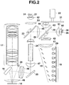
- the light source unit 15 includes LD 18 that emits blue laser light.
- the blue laser light (B) emitted by LD 18 is reflected by a mirror 19, passes through a dichroic mirror wheel 20, and is delivered to a peripheral surface of a fluorescent wheel 21.
- the fluorescent wheel 21 is rotated by a wheel motor (M) 22 and forms a phosphor layer 21g all over the peripheral surface irradiated with the blue laser light.
- the phosphor layer 21g is formed by coating a phosphor on the circumference of the fluorescent wheel 21 irradiated with the laser light.
- a reflector is provided on the back of the surface of the fluorescent wheel 21 in which the phosphor layer 21g is formed so that the reflector overlaps the phosphor layer 21g.
- green light When the phosphor layer 21g of the fluorescent wheel 21 is irradiated with blue laser light, green light (G) is excited as reflected light.
- the green light is reflected by the dichroic mirror wheel 20 and also by a diachronic mirror wheel 23.
- the reflected light is converted into a luminous flux with an even luminance distribution by an integrator 24.
- the luminous flux is then reflected by a mirror 25, and reaches the mirror 16.
- the light source unit 15 further includes LED 26 that emits red light and LED 27 that emits blue light.
- the red light (R) emitted by LED 26 passes through the dichroic mirror wheel 20 and is then reflected by the dichroic mirror wheel 23.
- the reflected light is converted into a luminous flux with an even luminance distribution by the integrator 24.
- the luminous flux is then reflected by the mirror 25, and reaches the mirror 16.
- the blue light (B) emitted by LED 27 passes through the dichroic mirror wheel 23, and is converted into a luminous flux with an even luminance distribution by the integrator 24. The luminous flux is then reflected by the mirror 25, and reaches the mirror 16.
- the dichroic mirror wheel 20 allows the blue light and the red light to pass through, while reflecting the green light.
- the dichroic mirror wheel 23 allows the blue light to pass through, while reflecting the green light and the red light.
- the micro mirror element 14 performs an operation of distributing the reflected light to allow light failing to be reflected toward the projection lens unit 17, that is, what is called "off light” to enter the illuminance sensor 28, serving as a measurement unit.
- the illuminance sensor 28 measures the illuminance of incident light and outputs, to the above-described projection processing unit 13, a signal Ilm indicative of the result of measurement of the illuminance of light during an R field period, a signal IIlm indicative of the result of measurement of the illuminance of light during a G field period, and a signal IIIlm indicative of the result of measurement of the illuminance of light during a B field period, as described below in detail.
- LD 18 is provided with a temperature sensor 29 installed away from the light emission direction of LD 18 and serving as a temperature detection unit.
- LD 26 is provided with a temperature sensor 30 installed away from the light emission direction of LD 26
- LD 27 is provided with a temperature sensor 31 installed away from the light emission direction of LED 27.
- CPU 34 performs various projection operations in response to key operation signals from an operation unit 37.
- the operation unit 37 includes a key operation unit provided on the main body of the data projector apparatus 10 and an infrared light reception unit that receives infrared light from a remote controller (not shown in the drawings) dedicated to the data projector apparatus 10.
- the operation unit 37 outputs key operation signals based on keys operated by a user using the key operation unit or the remote controller, directly to CPU 31.
- the CPU 34 is also connected to a sound processing unit 38 via the system bus SB.
- the sound processing unit 38 includes a sound source circuit such as a PCM sound source.
- the sound processing unit 38 converts sound data provided during a projection operation into analog data, and drives a speaker unit 39 to amplify and emit sound or generate a beep or the like as needed.
- LD 18 includes an LD array with a plurality of, for example, 6 ⁇ 4 (the direction of the sheet of the drawing), that is, a total of 24 LDs arranged in a matrix and emit light.
- the output blue laser light is reflected by a mirror 19 including a stepped array of mirrors arranged in a matrix and which are identical to LDs 18 in number.
- the green light excited by the phosphor layer 21g of the fluorescent wheel 21 is reflected by the reflector provided on the back of the surface of the fluorescent wheel 21 in which the phosphor layer 21g is formed.
- the reflected green light is further reflected by the dichroic mirror wheel 20 via the lenses 43 and 44, passes through a lens 45, and is reflected by the dichroic mirror wheel 23.
- the green light reflected by the dichroic mirror wheel 23 is reflected by the mirror 25 via a lens 46, the integrator 24, and a lens 47, and passes though a lens 48 to the mirror 16.
- the green light reflected by the mirror 16 is delivered to the micro mirror element 14 via a lens 49, and the micro mirror element 14 forms an optical image in the corresponding color.
- the optical image formed is output toward the projection lens unit 17 via the lens 49.
- the red light emitted by LED 26 passes through the dichroic mirror wheel 20 via lenses 50 and 51, and is reflected by the dichroic mirror wheel 23 via the lens 45.
- the blue light emitted by LED 27 passes through the dichroic mirror wheel 23 via lenses 52 and 53.
- one color image frame is projected by, for example, forming the frame using four fields for R (Red), G (Green), W (White), and B (Blue), respectively, and projecting an image in these colors.
- R Red
- G Green
- W White
- B Blue
- FIG. 3 is a flowchart illustrating the contents of processing mainly for correcting the color balance among light sources which processing is carried out while the data projector apparatus 10 is powered on.
- CPU 34 carries out processing for an ordinary projection operation in which the micro mirror element 14 forms an optical image according to an image signal input by the input unit 11 and in which light from the light source unit 15 is projected by the projection lens unit 17 (step S101).
- CPU 34 determines whether or not the next frame timing is intended for correction of the color balance among the light sources (step S102).
- one frame timing for connection of the color balance among the light sources is assumed to be provided for every hour and the frame rate is 60 [frames/second], one frame timing is provided for every 216,000 frames.
- CPU 34 determines that the next frame timing is not intended for correction of the color balance among the light sources, CPU 34 makes the corresponding determination in step S102 and returns to the processing starting in step S101.
- CPU 34 waits for a frame timing intended for correction of the color balance among the light sources.
- CPU 34 makes the corresponding determination in the above-described step S102.
- CPU 34 then carries out projection by allowing the micro mirror element 14 to display an entirely black image throughout the period of an R field positioned at the head of the subsequent one frame (step S103).
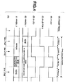
- FIG. 4 shows operational timings during an image projection period for one frame intended for correction of the color balance among the light sources.
- the one frame includes four fields: an R field, a G field, a W field, and a B field.
- the field periods are assumed to have an equal length.
- CPU 34 corrects the measurement result from the illuminance sensor 28 based on the detection result ThR from the temperature sensor 30.
- CPU 34 can thus determine the accurate light emission output from LED 26 and calculate the adjusted value for the light emission output, that is, the correct driving current value.
- the data projector apparatus 10 uses the rotating dichroic mirror wheels to guide light to the integrator 24.
- the data projector apparatus 10 may of course be constructed by using dichroic mirrors that are not rotatable.
- lookup tables for allowing the light source illuminance to be corrected may be pre-stored in the program memory.
- lookup tables as shown in FIGS. 7 and 8 are used.
- FIG. 7 is a schematic diagram of lookup tables that allow determination of correction factors for use in finding correction values based on the measured values of the light source illuminances and the temperatures of the light sources.
- FIG. 8 is a schematic diagram of a lookup table (R corrected current ir' table) that allows a driving current value for the red light source LED 26 to be determined based on the correction factor determined in FIG. 7 .
- the lookup tables are simplified for description. For example, in the table of FIG. 8 , the unit "[A]" for each current value is omitted except the upper left portion.
- the temperature of LED 27 is measured using the temperature sensor 31, and the illuminance at that measurement point of time is measured using the illuminance sensor 28. Then, a blue correction factor Ab is determined using a temperature and an illuminance obtained by referencing a B corrected value Ab table, one of the lookup tables in FIG. 7 .
Landscapes
- Engineering & Computer Science (AREA)
- Multimedia (AREA)
- Signal Processing (AREA)
- Physics & Mathematics (AREA)
- Computer Hardware Design (AREA)
- General Physics & Mathematics (AREA)
- Theoretical Computer Science (AREA)
- Optics & Photonics (AREA)
- Projection Apparatus (AREA)
- Led Device Packages (AREA)
- Semiconductor Lasers (AREA)
Claims (5)
- Appareil de projection (10) comprenant :une unité de source de lumière (15) ayant une pluralité de types différents d'éléments électroluminescents à semi-conducteur (18, 26, 27) ayant différentes longueurs d'onde d'émission de lumièreet configurée pour délivrer en sortie de manière cyclique des faisceaux lumineux dans des couleurs primaires et des faisceaux lumineux dans lesquels la pluralité de types différents des éléments électroluminescents à semi-conducteur (18, 26, 27) émettent simultanément de la lumière d'une manière par répartition dans le temps ;une unité d'entrée (11) configurée pour entrer un signal d'image ;une unité de formation d'image optique (14) configurée pour former une image optique en fonction du signal d'image entré par l'unité d'entrée (11) en utilisant de la lumière émise par les éléments électroluminescents à semi-conducteur (18, 26, 27) ;une unité de projection (17) configurée pour projeter l'image optique formée par l'unité de formation d'image optique (14) vers une cible de projection ;une pluralité d'unités de détection de température (29-31), chacune étant configurée pour détecter, pendant une correction de balance des couleurs, une température d'un type respectif d'élément électroluminescent à semi-conducteur (18, 26, 27) pendant une émission de lumière de couleurs primaires respective ;une unité de mesure (28) configurée pour mesurer, pendant la correction de balance des couleurs, une intensité de lumière provenant de chaque type d'éléments électroluminescents à semi-conducteur (18, 26, 27) pendant une émission de couleurs primaires respective en utilisant une lumière réfléchie qui n'est pas réfléchie vers l'unité de projection (17) par l'unité de formation d'image optique (14), dans lequel l'unité de formation d'image optique (14) est en outre configurée, pendant la correction de balance des couleurs, pour former une image optique entièrement noire pendant une période au cours de laquelle un type unique d'éléments électroluminescents à semi-conducteur (18, 26, 27) émet une couleur primaire, et pour former une image optique correspondant à un signal de luminance en fonction du signal d'image entré par l'unité d'entrée (11) pendant une période au cours de laquelle la pluralité de types différents des éléments électroluminescents à semi-conducteur (18, 26, 27) émettent simultanément de la lumière ; etune unité de commande d'émission de lumière (34) configurée (a) pour corriger, pendant la correction de balance des couleurs, un résultat de mesure provenant de l'unité de mesure (28) en utilisant un résultat de détection provenant des unités de détection de température (29-31) en prenant en compte un décalage de longueur d'onde induit par température des différents types d'éléments électroluminescents à semi-conducteur et un changement associé de la sensibilité de l'unité de mesure et (b) pour commander l'intensité d'émission de lumière pour chacun des éléments électroluminescents à semi-conducteur (18, 26, 27) sur la base du résultat de mesure corrigé, en maintenant ainsi la balance des couleurs parmi les éléments électroluminescents à semi-conducteur.
- Appareil de projection (10) selon la revendication 1, dans lequel la pluralité d'unités de détection de température (29-31) et l'unité de mesure (28) sont configurées pour détecter la température de chaque type des éléments électroluminescents à semi-conducteur (18, 26, 27) et pour mesurer l'intensité lumineuse provenant de chaque type des éléments électroluminescents à semi-conducteur (18, 26, 27), respectivement, pendant l'émission de lumière à un instant correspondant à un centre significatif de chaque période d'émission de couleurs primaires.
- Appareil de projection (10) selon la revendication 1, dans lequel l'unité de commande d'émission de lumière (34) est configurée(a) pour effectuer une opération arithmétique prédéterminée sur la base du résultat de détection provenant des unités de détection de température (29-31),(b) pour corriger le résultat de mesure provenant de l'unité de mesure (28) en fonction d'un résultat de calcul de l'opération arithmétique, et ensuite(c) pour commander l'intensité d'émission de lumière de chacun des éléments électroluminescents à semi-conducteur (18, 26, 27) sur la base du résultat de mesure corrigé.
- Appareil de projection (10) selon la revendication 1, dans lequel l'unité de commande d'émission de lumière (34) est configurée(a) pour référencer une table de consultation prédéterminée et pour corriger le résultat de mesure provenant de l'unité de mesure (28) sur la base du résultat de détection provenant des unités de détection de température (29-31), et ensuite(b) pour commander l'intensité d'émission de lumière de chacun des éléments électroluminescents à semi-conducteur (18, 26, 27) sur la base des facteurs de correction.
- Procédé de projection appliqué à un appareil (10) comprenant une unité de source de lumière (15) ayant une pluralité de types différents d'éléments électroluminescents à semi-conducteur (18, 26, 27) ayant différentes longueurs d'onde d'émission de lumière et délivrant en sortie de manière cyclique des faisceaux lumineux dans des couleurs primaires et des faisceaux lumineux dans lesquels la pluralité de types différents des éléments électroluminescents à semi-conducteur (18, 26, 27) émettent simultanément de la lumière d'une manière par répartition dans le temps, une unité d'entrée (11) configurée pour entrer un signal d'image, une unité de formation d'image optique (14) qui forme une image optique en fonction du signal d'image entré par l'unité d'entrée (11) en utilisant de la lumière émise par les éléments électroluminescents à semi-conducteur (18, 26, 27), et une unité de projection (17) qui projette l'image optique formée par l'unité de formation d'image optique (14) vers une cible de projection le procédé comprenant les étapes consistant à :détecter (S104, S107, S111), pendant une correction de balance des couleurs, une température de chaque type d'éléments électroluminescents à semi-conducteur (18, 26, 27) pendant une émission de couleurs primaires respective ;mesurer (S104, S107, S111), pendant la correction de balance des couleurs, une intensité de lumière provenant de chaque type des éléments électroluminescents à semi-conducteur (18, 26, 27) pendant une émission de couleurs primaires respective en utilisant une lumière réfléchie qui n'est pas réfléchie vers l'unité de projection (17) par l'unité de formation d'image optique (14) ;former (S103, S106, S110), pendant la correction de balance des couleurs, une image optique entièrement noire pendant une période au cours de laquelle un type unique d'éléments électroluminescents à semi-conducteur (18, 26, 27) émet une couleur primaire ;former (S109), pendant la correction de balance des couleurs, une image optique correspondant à un signal de luminance en fonction du signal d'image entré par l'unité d'entrée (11) pendant une période au cours de laquelle la pluralité de types différents des éléments électroluminescents à semi-conducteur (18, 26, 27) émettent simultanément de la lumière ;corriger (S105, S108, S112), pendant la correction de balance des couleurs, un résultat de mesure obtenu lors de la mesure de l'intensité de lumière en utilisant un résultat de détection obtenu lors de la détection de température en prenant en compte un décalage de longueur d'onde induit par température des différents types d'éléments électroluminescents à semi-conducteur et un changement associé de la sensibilité de l'unité de mesure ; etcommander (S113) l'intensité d'émission de lumière pour chacun des éléments électroluminescents à semi-conducteur (18, 26, 27) sur la base du résultat de mesure corrigé, en maintenant ainsi la balance des couleurs parmi différents types d'éléments électroluminescents à semi-conducteur.
Applications Claiming Priority (2)
| Application Number | Priority Date | Filing Date | Title |
|---|---|---|---|
| JP2011070007 | 2011-03-28 | ||
| JP2012051992A JP5408278B2 (ja) | 2011-03-28 | 2012-03-08 | 投影装置、投影方法及びプログラム |
Publications (3)
| Publication Number | Publication Date |
|---|---|
| EP2506573A2 EP2506573A2 (fr) | 2012-10-03 |
| EP2506573A3 EP2506573A3 (fr) | 2017-01-25 |
| EP2506573B1 true EP2506573B1 (fr) | 2021-06-30 |
Family
ID=46062032
Family Applications (1)
| Application Number | Title | Priority Date | Filing Date |
|---|---|---|---|
| EP12161632.0A Active EP2506573B1 (fr) | 2011-03-28 | 2012-03-28 | Dispositif d'affichage par projection et procédé d'affichage par projection |
Country Status (3)
| Country | Link |
|---|---|
| US (1) | US8794765B2 (fr) |
| EP (1) | EP2506573B1 (fr) |
| JP (1) | JP5408278B2 (fr) |
Families Citing this family (26)
| Publication number | Priority date | Publication date | Assignee | Title |
|---|---|---|---|---|
| JP5703631B2 (ja) | 2010-08-26 | 2015-04-22 | セイコーエプソン株式会社 | プロジェクター |
| CN103376634B (zh) * | 2012-04-24 | 2015-11-18 | 中强光电股份有限公司 | 光源模组与投影装置 |
| DE102012013028A1 (de) * | 2012-07-02 | 2014-01-02 | Infitec Gmbh | Stereoprojektionsvorrichtung und Verfahren zur Projektion von stereoskopischen Bildern |
| JP6056293B2 (ja) * | 2012-09-12 | 2017-01-11 | 株式会社リコー | 照明光源装置及びこの照明光源装置を備えた投射装置及び投射装置の制御方法 |
| US9769439B2 (en) * | 2013-01-04 | 2017-09-19 | Seiko Epson Corporation | Projector and method for controlling the same the same that adjust light source output based on a corrected detected light brightness |
| JP6286825B2 (ja) * | 2013-01-04 | 2018-03-07 | セイコーエプソン株式会社 | プロジェクター及びその制御方法 |
| JP6252081B2 (ja) * | 2013-10-03 | 2017-12-27 | セイコーエプソン株式会社 | プロジェクター及びその制御方法 |
| JP5956949B2 (ja) * | 2013-03-22 | 2016-07-27 | 株式会社日立エルジーデータストレージ | 画像表示装置 |
| WO2014192115A1 (fr) * | 2013-05-30 | 2014-12-04 | Necディスプレイソリューションズ株式会社 | Dispositif de source de lumière et dispositif d'affichage du type à projection |
| JP6229316B2 (ja) * | 2013-06-03 | 2017-11-15 | セイコーエプソン株式会社 | 光源装置およびプロジェクター |
| JP2015022096A (ja) * | 2013-07-18 | 2015-02-02 | 株式会社日立エルジーデータストレージ | 画像表示装置 |
| JP2015148782A (ja) | 2014-02-10 | 2015-08-20 | ソニー株式会社 | 画像表示装置及び表示装置 |
| JP6314518B2 (ja) * | 2014-02-10 | 2018-04-25 | ソニー株式会社 | 画像表示装置及び表示装置 |
| CN106233200B (zh) * | 2014-05-09 | 2018-07-17 | 麦克赛尔株式会社 | 投影型影像显示装置 |
| JP6476602B2 (ja) * | 2014-06-13 | 2019-03-06 | 株式会社リコー | 光源装置及び投影表示装置 |
| CN104166300B (zh) * | 2014-07-24 | 2016-01-20 | 杭州虹视科技有限公司 | 一种激光显示系统 |
| CN105491359B (zh) * | 2014-10-13 | 2018-07-06 | 联想(北京)有限公司 | 投影设备、投影系统和投影方法 |
| CN107113393A (zh) * | 2014-12-24 | 2017-08-29 | 富士胶片株式会社 | 投射型显示装置及其光源控制方法 |
| JP6623779B2 (ja) * | 2016-01-15 | 2019-12-25 | セイコーエプソン株式会社 | プロジェクター、及び、光源制御方法 |
| JP6631273B2 (ja) * | 2016-01-25 | 2020-01-15 | 株式会社リコー | 画像投射装置 |
| JP6731784B2 (ja) * | 2016-05-20 | 2020-07-29 | 三菱電機株式会社 | 光源装置および映像表示装置 |
| GB201622220D0 (en) | 2016-12-23 | 2017-02-08 | Barco Nv | Cooling system for spatial light modulating devices |
| JP6468323B2 (ja) * | 2017-07-20 | 2019-02-13 | カシオ計算機株式会社 | 光源ユニット、投影装置、投影方法及びプログラム |
| CN109917610B (zh) | 2017-12-12 | 2020-12-01 | 中强光电股份有限公司 | 光源模块以及投影装置 |
| CN110888293B (zh) * | 2018-09-10 | 2022-09-16 | 深圳光峰科技股份有限公司 | 投影装置、白平衡的预设方法及实现方法 |
| JP7001974B2 (ja) * | 2019-09-03 | 2022-02-04 | カシオ計算機株式会社 | 光源装置及び投影装置 |
Citations (1)
| Publication number | Priority date | Publication date | Assignee | Title |
|---|---|---|---|---|
| US20070070296A1 (en) * | 2005-09-29 | 2007-03-29 | Casio Computer Co., Ltd. | Projector and method of controlling a light source for use with the projector |
Family Cites Families (25)
| Publication number | Priority date | Publication date | Assignee | Title |
|---|---|---|---|---|
| JP3939141B2 (ja) | 2001-12-05 | 2007-07-04 | オリンパス株式会社 | 投射型画像表示システム及びその色補正方法 |
| JP2004184852A (ja) | 2002-12-05 | 2004-07-02 | Olympus Corp | 表示装置、光源装置、及び照明装置 |
| JP3902128B2 (ja) | 2002-12-19 | 2007-04-04 | 株式会社アドバンスト・ディスプレイ | 透過型表示装置の表示色制御方法 |
| JP4254317B2 (ja) | 2003-04-11 | 2009-04-15 | セイコーエプソン株式会社 | 表示装置、プロジェクタ、及びそれらの駆動方法 |
| JP2004341206A (ja) | 2003-05-15 | 2004-12-02 | Olympus Corp | 表示装置 |
| JP2005106951A (ja) | 2003-09-29 | 2005-04-21 | Seiko Epson Corp | プロジェクタおよびプロジェクタ用光源ランプの駆動制御 |
| JP4426281B2 (ja) | 2003-12-25 | 2010-03-03 | 船井電機株式会社 | プロジェクタ装置 |
| JP2005208231A (ja) * | 2004-01-21 | 2005-08-04 | Seiko Epson Corp | 光源装置、光源装置用制御装置、光源装置の制御方法及びプロジェクタ |
| JP4217643B2 (ja) * | 2004-03-18 | 2009-02-04 | キヤノン株式会社 | 画像濃度補正方法及び画像濃度補正システム |
| JP4107266B2 (ja) * | 2004-06-11 | 2008-06-25 | セイコーエプソン株式会社 | 表示装置及びその調光方法 |
| JP2006163360A (ja) * | 2004-11-11 | 2006-06-22 | Casio Comput Co Ltd | 投影装置、投影方法、投影制御プログラム |
| KR100643774B1 (ko) * | 2005-03-09 | 2006-11-10 | 삼성전자주식회사 | 발광다이오드 광원의 온도 및 발광레벨을 감안하여 화이트밸런스를 조정하는 영상투사장치 및 그의 화이트밸런스 조정방법 |
| JP2006330177A (ja) | 2005-05-24 | 2006-12-07 | Olympus Corp | 表示装置及びプロジェクタ |
| US20090128451A1 (en) | 2005-08-25 | 2009-05-21 | Kei Tokui | Image display device |
| JP4903407B2 (ja) | 2005-08-29 | 2012-03-28 | Necディスプレイソリューションズ株式会社 | 投射型表示装置の光の調整方法 |
| JP2008079113A (ja) | 2006-09-22 | 2008-04-03 | Seiko Epson Corp | プロジェクタおよび調整方法 |
| JP5175504B2 (ja) | 2006-10-10 | 2013-04-03 | 三洋電機株式会社 | 投写型映像表示装置 |
| JP2008177049A (ja) | 2007-01-18 | 2008-07-31 | Sharp Corp | 点灯装置及びプロジェクタ |
| JP2008192421A (ja) | 2007-02-02 | 2008-08-21 | Seiko Epson Corp | 光源制御装置、画像表示装置およびプロジェクタ |
| JP5095311B2 (ja) * | 2007-08-30 | 2012-12-12 | 株式会社日立製作所 | 画像表示装置、及び画像表示装置における反射鏡の振動状態調整方法 |
| US7874681B2 (en) * | 2007-10-05 | 2011-01-25 | Huebner Kenneth J | Interactive projector system and method |
| JP5399035B2 (ja) * | 2007-10-24 | 2014-01-29 | 三洋電機株式会社 | 投写型映像表示装置 |
| JP4525767B2 (ja) * | 2008-02-14 | 2010-08-18 | ソニー株式会社 | 照明装置及び表示装置 |
| JP4743318B2 (ja) | 2008-11-27 | 2011-08-10 | カシオ計算機株式会社 | 投影装置、投影方法及びプログラム |
| US8585213B2 (en) * | 2009-05-28 | 2013-11-19 | Transpacific Image, Llc | Projection-type display and control thereof |
-
2012
- 2012-03-08 JP JP2012051992A patent/JP5408278B2/ja active Active
- 2012-03-27 US US13/431,462 patent/US8794765B2/en active Active
- 2012-03-28 EP EP12161632.0A patent/EP2506573B1/fr active Active
Patent Citations (1)
| Publication number | Priority date | Publication date | Assignee | Title |
|---|---|---|---|---|
| US20070070296A1 (en) * | 2005-09-29 | 2007-03-29 | Casio Computer Co., Ltd. | Projector and method of controlling a light source for use with the projector |
Also Published As
| Publication number | Publication date |
|---|---|
| US20120249976A1 (en) | 2012-10-04 |
| JP2012215846A (ja) | 2012-11-08 |
| EP2506573A3 (fr) | 2017-01-25 |
| JP5408278B2 (ja) | 2014-02-05 |
| EP2506573A2 (fr) | 2012-10-03 |
| US8794765B2 (en) | 2014-08-05 |
Similar Documents
| Publication | Publication Date | Title |
|---|---|---|
| EP2506573B1 (fr) | Dispositif d'affichage par projection et procédé d'affichage par projection | |
| TWI446095B (zh) | 投影裝置、投影方法及程式 | |
| TWI438546B (zh) | 投影裝置、利用投影裝置的投影方法、及非暫態電腦可讀取記錄媒體 | |
| TWI439726B (zh) | 光源裝置、投影裝置及投影方法 | |
| TWI524127B (zh) | 光源裝置、投影裝置、投影方法及記錄媒體 | |
| US8403493B2 (en) | Projection apparatus and projection method for controlling emission of plural color light sources having different luminous efficiencies | |
| JP6019859B2 (ja) | プロジェクター、及び、プロジェクターにおける発光制御方法 | |
| TWI414874B (zh) | 使用發光色相異之複數個光源以進行脈衝驅動之投影裝置 | |
| JP5625675B2 (ja) | 投影装置、投影方法及びプログラム | |
| TW201316041A (zh) | 投影裝置及投影控制方法 | |
| JP5640761B2 (ja) | 投影装置、投影方法及びプログラム | |
| US9057937B2 (en) | Image projection device and color correction method | |
| JP5930001B2 (ja) | 投影装置 | |
| JP2012053279A (ja) | カラー画像形成装置、カラー画像形成方法及びこのカラー画像形成装置を備えた投影装置 | |
| JP6135037B2 (ja) | 投影装置、投影方法及びプログラム | |
| JP4133886B2 (ja) | プロジェクタ装置及びプロジェクタ装置における色補正方法 | |
| JP2014120796A (ja) | 画像表示装置 | |
| JP5574179B2 (ja) | プロジェクタにおける階調補正方法及びプロジェクタ | |
| JP2017010057A (ja) | プロジェクター、及び、プロジェクターにおける発光制御方法 | |
| JP2010066465A (ja) | 画像表示装置 | |
| JP4715244B2 (ja) | 投写装置 | |
| JP7303990B2 (ja) | 投影装置、投影制御装置及びプログラム | |
| JP2017182071A (ja) | 投影装置、投影方法及びプログラム | |
| JP6186687B2 (ja) | 表示装置、表示方法及びプログラム |
Legal Events
| Date | Code | Title | Description |
|---|---|---|---|
| PUAI | Public reference made under article 153(3) epc to a published international application that has entered the european phase |
Free format text: ORIGINAL CODE: 0009012 |
|
| 17P | Request for examination filed |
Effective date: 20120328 |
|
| AK | Designated contracting states |
Kind code of ref document: A2 Designated state(s): AL AT BE BG CH CY CZ DE DK EE ES FI FR GB GR HR HU IE IS IT LI LT LU LV MC MK MT NL NO PL PT RO RS SE SI SK SM TR |
|
| AX | Request for extension of the european patent |
Extension state: BA ME |
|
| PUAL | Search report despatched |
Free format text: ORIGINAL CODE: 0009013 |
|
| AK | Designated contracting states |
Kind code of ref document: A3 Designated state(s): AL AT BE BG CH CY CZ DE DK EE ES FI FR GB GR HR HU IE IS IT LI LT LU LV MC MK MT NL NO PL PT RO RS SE SI SK SM TR |
|
| AX | Request for extension of the european patent |
Extension state: BA ME |
|
| RIC1 | Information provided on ipc code assigned before grant |
Ipc: H04N 9/31 20060101AFI20161216BHEP |
|
| STAA | Information on the status of an ep patent application or granted ep patent |
Free format text: STATUS: EXAMINATION IS IN PROGRESS |
|
| 17Q | First examination report despatched |
Effective date: 20200131 |
|
| GRAP | Despatch of communication of intention to grant a patent |
Free format text: ORIGINAL CODE: EPIDOSNIGR1 |
|
| STAA | Information on the status of an ep patent application or granted ep patent |
Free format text: STATUS: GRANT OF PATENT IS INTENDED |
|
| INTG | Intention to grant announced |
Effective date: 20210226 |
|
| GRAS | Grant fee paid |
Free format text: ORIGINAL CODE: EPIDOSNIGR3 |
|
| GRAA | (expected) grant |
Free format text: ORIGINAL CODE: 0009210 |
|
| STAA | Information on the status of an ep patent application or granted ep patent |
Free format text: STATUS: THE PATENT HAS BEEN GRANTED |
|
| AK | Designated contracting states |
Kind code of ref document: B1 Designated state(s): AL AT BE BG CH CY CZ DE DK EE ES FI FR GB GR HR HU IE IS IT LI LT LU LV MC MK MT NL NO PL PT RO RS SE SI SK SM TR |
|
| REG | Reference to a national code |
Ref country code: GB Ref legal event code: FG4D Ref country code: CH Ref legal event code: EP |
|
| REG | Reference to a national code |
Ref country code: DE Ref legal event code: R096 Ref document number: 602012075949 Country of ref document: DE Ref country code: AT Ref legal event code: REF Ref document number: 1407484 Country of ref document: AT Kind code of ref document: T Effective date: 20210715 |
|
| REG | Reference to a national code |
Ref country code: IE Ref legal event code: FG4D |
|
| REG | Reference to a national code |
Ref country code: LT Ref legal event code: MG9D |
|
| PG25 | Lapsed in a contracting state [announced via postgrant information from national office to epo] |
Ref country code: FI Free format text: LAPSE BECAUSE OF FAILURE TO SUBMIT A TRANSLATION OF THE DESCRIPTION OR TO PAY THE FEE WITHIN THE PRESCRIBED TIME-LIMIT Effective date: 20210630 Ref country code: BG Free format text: LAPSE BECAUSE OF FAILURE TO SUBMIT A TRANSLATION OF THE DESCRIPTION OR TO PAY THE FEE WITHIN THE PRESCRIBED TIME-LIMIT Effective date: 20210930 Ref country code: HR Free format text: LAPSE BECAUSE OF FAILURE TO SUBMIT A TRANSLATION OF THE DESCRIPTION OR TO PAY THE FEE WITHIN THE PRESCRIBED TIME-LIMIT Effective date: 20210630 |
|
| REG | Reference to a national code |
Ref country code: NL Ref legal event code: MP Effective date: 20210630 |
|
| REG | Reference to a national code |
Ref country code: AT Ref legal event code: MK05 Ref document number: 1407484 Country of ref document: AT Kind code of ref document: T Effective date: 20210630 |
|
| PG25 | Lapsed in a contracting state [announced via postgrant information from national office to epo] |
Ref country code: NO Free format text: LAPSE BECAUSE OF FAILURE TO SUBMIT A TRANSLATION OF THE DESCRIPTION OR TO PAY THE FEE WITHIN THE PRESCRIBED TIME-LIMIT Effective date: 20210930 Ref country code: RS Free format text: LAPSE BECAUSE OF FAILURE TO SUBMIT A TRANSLATION OF THE DESCRIPTION OR TO PAY THE FEE WITHIN THE PRESCRIBED TIME-LIMIT Effective date: 20210630 Ref country code: SE Free format text: LAPSE BECAUSE OF FAILURE TO SUBMIT A TRANSLATION OF THE DESCRIPTION OR TO PAY THE FEE WITHIN THE PRESCRIBED TIME-LIMIT Effective date: 20210630 Ref country code: LV Free format text: LAPSE BECAUSE OF FAILURE TO SUBMIT A TRANSLATION OF THE DESCRIPTION OR TO PAY THE FEE WITHIN THE PRESCRIBED TIME-LIMIT Effective date: 20210630 Ref country code: GR Free format text: LAPSE BECAUSE OF FAILURE TO SUBMIT A TRANSLATION OF THE DESCRIPTION OR TO PAY THE FEE WITHIN THE PRESCRIBED TIME-LIMIT Effective date: 20211001 |
|
| PG25 | Lapsed in a contracting state [announced via postgrant information from national office to epo] |
Ref country code: AT Free format text: LAPSE BECAUSE OF FAILURE TO SUBMIT A TRANSLATION OF THE DESCRIPTION OR TO PAY THE FEE WITHIN THE PRESCRIBED TIME-LIMIT Effective date: 20210630 Ref country code: ES Free format text: LAPSE BECAUSE OF FAILURE TO SUBMIT A TRANSLATION OF THE DESCRIPTION OR TO PAY THE FEE WITHIN THE PRESCRIBED TIME-LIMIT Effective date: 20210630 Ref country code: PT Free format text: LAPSE BECAUSE OF FAILURE TO SUBMIT A TRANSLATION OF THE DESCRIPTION OR TO PAY THE FEE WITHIN THE PRESCRIBED TIME-LIMIT Effective date: 20211102 Ref country code: NL Free format text: LAPSE BECAUSE OF FAILURE TO SUBMIT A TRANSLATION OF THE DESCRIPTION OR TO PAY THE FEE WITHIN THE PRESCRIBED TIME-LIMIT Effective date: 20210630 Ref country code: RO Free format text: LAPSE BECAUSE OF FAILURE TO SUBMIT A TRANSLATION OF THE DESCRIPTION OR TO PAY THE FEE WITHIN THE PRESCRIBED TIME-LIMIT Effective date: 20210630 Ref country code: SK Free format text: LAPSE BECAUSE OF FAILURE TO SUBMIT A TRANSLATION OF THE DESCRIPTION OR TO PAY THE FEE WITHIN THE PRESCRIBED TIME-LIMIT Effective date: 20210630 Ref country code: SM Free format text: LAPSE BECAUSE OF FAILURE TO SUBMIT A TRANSLATION OF THE DESCRIPTION OR TO PAY THE FEE WITHIN THE PRESCRIBED TIME-LIMIT Effective date: 20210630 Ref country code: CZ Free format text: LAPSE BECAUSE OF FAILURE TO SUBMIT A TRANSLATION OF THE DESCRIPTION OR TO PAY THE FEE WITHIN THE PRESCRIBED TIME-LIMIT Effective date: 20210630 Ref country code: EE Free format text: LAPSE BECAUSE OF FAILURE TO SUBMIT A TRANSLATION OF THE DESCRIPTION OR TO PAY THE FEE WITHIN THE PRESCRIBED TIME-LIMIT Effective date: 20210630 |
|
| PG25 | Lapsed in a contracting state [announced via postgrant information from national office to epo] |
Ref country code: PL Free format text: LAPSE BECAUSE OF FAILURE TO SUBMIT A TRANSLATION OF THE DESCRIPTION OR TO PAY THE FEE WITHIN THE PRESCRIBED TIME-LIMIT Effective date: 20210630 |
|
| REG | Reference to a national code |
Ref country code: DE Ref legal event code: R097 Ref document number: 602012075949 Country of ref document: DE |
|
| PG25 | Lapsed in a contracting state [announced via postgrant information from national office to epo] |
Ref country code: DK Free format text: LAPSE BECAUSE OF FAILURE TO SUBMIT A TRANSLATION OF THE DESCRIPTION OR TO PAY THE FEE WITHIN THE PRESCRIBED TIME-LIMIT Effective date: 20210630 |
|
| PLBE | No opposition filed within time limit |
Free format text: ORIGINAL CODE: 0009261 |
|
| STAA | Information on the status of an ep patent application or granted ep patent |
Free format text: STATUS: NO OPPOSITION FILED WITHIN TIME LIMIT |
|
| PG25 | Lapsed in a contracting state [announced via postgrant information from national office to epo] |
Ref country code: AL Free format text: LAPSE BECAUSE OF FAILURE TO SUBMIT A TRANSLATION OF THE DESCRIPTION OR TO PAY THE FEE WITHIN THE PRESCRIBED TIME-LIMIT Effective date: 20210630 |
|
| 26N | No opposition filed |
Effective date: 20220331 |
|
| PG25 | Lapsed in a contracting state [announced via postgrant information from national office to epo] |
Ref country code: IT Free format text: LAPSE BECAUSE OF FAILURE TO SUBMIT A TRANSLATION OF THE DESCRIPTION OR TO PAY THE FEE WITHIN THE PRESCRIBED TIME-LIMIT Effective date: 20210630 |
|
| PG25 | Lapsed in a contracting state [announced via postgrant information from national office to epo] |
Ref country code: MC Free format text: LAPSE BECAUSE OF FAILURE TO SUBMIT A TRANSLATION OF THE DESCRIPTION OR TO PAY THE FEE WITHIN THE PRESCRIBED TIME-LIMIT Effective date: 20210630 |
|
| REG | Reference to a national code |
Ref country code: CH Ref legal event code: PL |
|
| REG | Reference to a national code |
Ref country code: BE Ref legal event code: MM Effective date: 20220331 |
|
| PG25 | Lapsed in a contracting state [announced via postgrant information from national office to epo] |
Ref country code: LU Free format text: LAPSE BECAUSE OF NON-PAYMENT OF DUE FEES Effective date: 20220328 Ref country code: LI Free format text: LAPSE BECAUSE OF NON-PAYMENT OF DUE FEES Effective date: 20220331 Ref country code: IE Free format text: LAPSE BECAUSE OF NON-PAYMENT OF DUE FEES Effective date: 20220328 Ref country code: CH Free format text: LAPSE BECAUSE OF NON-PAYMENT OF DUE FEES Effective date: 20220331 |
|
| PG25 | Lapsed in a contracting state [announced via postgrant information from national office to epo] |
Ref country code: BE Free format text: LAPSE BECAUSE OF NON-PAYMENT OF DUE FEES Effective date: 20220331 |
|
| PG25 | Lapsed in a contracting state [announced via postgrant information from national office to epo] |
Ref country code: LT Free format text: LAPSE BECAUSE OF FAILURE TO SUBMIT A TRANSLATION OF THE DESCRIPTION OR TO PAY THE FEE WITHIN THE PRESCRIBED TIME-LIMIT Effective date: 20210630 |
|
| PG25 | Lapsed in a contracting state [announced via postgrant information from national office to epo] |
Ref country code: HU Free format text: LAPSE BECAUSE OF FAILURE TO SUBMIT A TRANSLATION OF THE DESCRIPTION OR TO PAY THE FEE WITHIN THE PRESCRIBED TIME-LIMIT; INVALID AB INITIO Effective date: 20120328 |
|
| PG25 | Lapsed in a contracting state [announced via postgrant information from national office to epo] |
Ref country code: MK Free format text: LAPSE BECAUSE OF FAILURE TO SUBMIT A TRANSLATION OF THE DESCRIPTION OR TO PAY THE FEE WITHIN THE PRESCRIBED TIME-LIMIT Effective date: 20210630 Ref country code: CY Free format text: LAPSE BECAUSE OF FAILURE TO SUBMIT A TRANSLATION OF THE DESCRIPTION OR TO PAY THE FEE WITHIN THE PRESCRIBED TIME-LIMIT Effective date: 20210630 |
|
| PG25 | Lapsed in a contracting state [announced via postgrant information from national office to epo] |
Ref country code: TR Free format text: LAPSE BECAUSE OF FAILURE TO SUBMIT A TRANSLATION OF THE DESCRIPTION OR TO PAY THE FEE WITHIN THE PRESCRIBED TIME-LIMIT Effective date: 20210630 |
|
| PG25 | Lapsed in a contracting state [announced via postgrant information from national office to epo] |
Ref country code: MT Free format text: LAPSE BECAUSE OF FAILURE TO SUBMIT A TRANSLATION OF THE DESCRIPTION OR TO PAY THE FEE WITHIN THE PRESCRIBED TIME-LIMIT Effective date: 20210630 |
|
| PGFP | Annual fee paid to national office [announced via postgrant information from national office to epo] |
Ref country code: GB Payment date: 20260209 Year of fee payment: 15 |
|
| PGFP | Annual fee paid to national office [announced via postgrant information from national office to epo] |
Ref country code: DE Payment date: 20260204 Year of fee payment: 15 |
|
| PGFP | Annual fee paid to national office [announced via postgrant information from national office to epo] |
Ref country code: FR Payment date: 20260209 Year of fee payment: 15 |