EP2507452B1 - Mécanisme de verrou détendeur de pression - Google Patents
Mécanisme de verrou détendeur de pression Download PDFInfo
- Publication number
- EP2507452B1 EP2507452B1 EP10835213.9A EP10835213A EP2507452B1 EP 2507452 B1 EP2507452 B1 EP 2507452B1 EP 10835213 A EP10835213 A EP 10835213A EP 2507452 B1 EP2507452 B1 EP 2507452B1
- Authority
- EP
- European Patent Office
- Prior art keywords
- bolt
- handle
- detent
- mounting bracket
- latch mechanism
- Prior art date
- Legal status (The legal status is an assumption and is not a legal conclusion. Google has not performed a legal analysis and makes no representation as to the accuracy of the status listed.)
- Active
Links
Images




Classifications
-
- E—FIXED CONSTRUCTIONS
- E05—LOCKS; KEYS; WINDOW OR DOOR FITTINGS; SAFES
- E05C—BOLTS OR FASTENING DEVICES FOR WINGS, SPECIALLY FOR DOORS OR WINDOWS
- E05C3/00—Fastening devices with bolts moving pivotally or rotatively
- E05C3/02—Fastening devices with bolts moving pivotally or rotatively without latching action
- E05C3/06—Fastening devices with bolts moving pivotally or rotatively without latching action with operating handle or equivalent member moving otherwise than rigidly with the bolt
- E05C3/08—Fastening devices with bolts moving pivotally or rotatively without latching action with operating handle or equivalent member moving otherwise than rigidly with the bolt the handle or member moving essentially towards or away from the plane of the wing or frame
-
- E—FIXED CONSTRUCTIONS
- E05—LOCKS; KEYS; WINDOW OR DOOR FITTINGS; SAFES
- E05B—LOCKS; ACCESSORIES THEREFOR; HANDCUFFS
- E05B5/00—Handles completely let into the surface of the wing
-
- E—FIXED CONSTRUCTIONS
- E05—LOCKS; KEYS; WINDOW OR DOOR FITTINGS; SAFES
- E05B—LOCKS; ACCESSORIES THEREFOR; HANDCUFFS
- E05B51/00—Operating or controlling locks or other fastening devices by other non-mechanical means
- E05B51/02—Operating or controlling locks or other fastening devices by other non-mechanical means by pneumatic or hydraulic means
- E05B51/023—Operating or controlling locks or other fastening devices by other non-mechanical means by pneumatic or hydraulic means actuated in response to external pressure, blast or explosion
-
- E—FIXED CONSTRUCTIONS
- E05—LOCKS; KEYS; WINDOW OR DOOR FITTINGS; SAFES
- E05B—LOCKS; ACCESSORIES THEREFOR; HANDCUFFS
- E05B63/00—Locks or fastenings with special structural characteristics
- E05B63/0065—Operating modes; Transformable to different operating modes
- E05B63/0069—Override systems, e.g. allowing opening from inside without the key, even when locked from outside
-
- B—PERFORMING OPERATIONS; TRANSPORTING
- B64—AIRCRAFT; AVIATION; COSMONAUTICS
- B64D—EQUIPMENT FOR FITTING IN OR TO AIRCRAFT; FLIGHT SUITS; PARACHUTES; ARRANGEMENT OR MOUNTING OF POWER PLANTS OR PROPULSION TRANSMISSIONS IN AIRCRAFT
- B64D29/00—Power-plant nacelles, fairings or cowlings
- B64D29/06—Attaching of nacelles, fairings or cowlings
-
- E—FIXED CONSTRUCTIONS
- E05—LOCKS; KEYS; WINDOW OR DOOR FITTINGS; SAFES
- E05B—LOCKS; ACCESSORIES THEREFOR; HANDCUFFS
- E05B15/00—Other details of locks; Parts for engagement by bolts of fastening devices
- E05B15/04—Spring arrangements in locks
- E05B2015/0403—Wound springs
- E05B2015/0406—Wound springs wound in a cylindrical shape
- E05B2015/0413—Wound springs wound in a cylindrical shape loaded by compression
-
- E—FIXED CONSTRUCTIONS
- E05—LOCKS; KEYS; WINDOW OR DOOR FITTINGS; SAFES
- E05B—LOCKS; ACCESSORIES THEREFOR; HANDCUFFS
- E05B15/00—Other details of locks; Parts for engagement by bolts of fastening devices
- E05B15/04—Spring arrangements in locks
- E05B2015/0431—Modifying spring characteristic or tension
-
- Y—GENERAL TAGGING OF NEW TECHNOLOGICAL DEVELOPMENTS; GENERAL TAGGING OF CROSS-SECTIONAL TECHNOLOGIES SPANNING OVER SEVERAL SECTIONS OF THE IPC; TECHNICAL SUBJECTS COVERED BY FORMER USPC CROSS-REFERENCE ART COLLECTIONS [XRACs] AND DIGESTS
- Y10—TECHNICAL SUBJECTS COVERED BY FORMER USPC
- Y10T—TECHNICAL SUBJECTS COVERED BY FORMER US CLASSIFICATION
- Y10T292/00—Closure fasteners
- Y10T292/08—Bolts
- Y10T292/1043—Swinging
- Y10T292/1075—Operating means
- Y10T292/1083—Rigid
Definitions
- the present disclosure relates to a pressure relief latch mechanism for releasably latching and/or holding a first member with respect to a second member, and in particular to a latch mechanism including a manually operable trigger for releasing a bolt of the latch mechanism from a latched condition and that is configured to alternatively automatically release the bolt of latch mechanism from the latched condition in response to an over-pressure condition encountered by the first member.
- EP 1 197 619 A1 discloses a blowout latch for releasably securing and aircraft panel to an aircraft structure.
- US 5 765 883 relates to a pressure relief latch for latching a first panel to a second panel and for release under pressure.
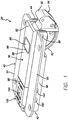
- latch mechanism 20 is adapted to releasably latch a first member 22 to a second member 24.
- First member 22 includes a first surface 26, a second surface 28 and an aperture 30 that extends through first member 22 from first surface 26 to second surface 28.
- Second member 24 includes a first surface 32 and a second surface 34.
- Second member 24 may be, for example, an aircraft frame or other body member.
- First member 22 may be, for example, a door or panel that is adapted to be removed or displaced with respect to second member 24.
- Latch mechanism 20 includes a mounting bracket 40 that extends between a first end 42 and a second end 44.
- Bracket 40 includes a pair of generally planar side walls 46 that are spaced apart and generally parallel to one another.
- a generally planar bottom wall 48 extends between the bottom ends of side walls 46 and is generally perpendicular to side walls 46, such that the side walls 46 and bottom wall 48 are generally U-shaped and form an open receptacle therebetween.
- a flange 50 extends outwardly and generally perpendicularly from the top end of each side wall 46.
- Each flange 50 includes one or more apertures adapted to receive a fastener for use in attaching bracket 40 in engagement with the second surface 28 of the first member 22 in alignment with aperture 30.
- Latch mechanism 20 includes a bolt 56 pivotally coupled to bracket 40 by a pin 58 having a generally linear central axis 60.
- Pin 58 extends generally transversely between side walls 46 of mounting bracket 40 and is coupled at each end to a respective side wall 46.
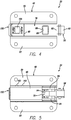
- Bolt 56 is pivotal with respect to bracket 40 about axis 60 from the retracted position as shown in Fig. 2 toward an extended position as shown in Figs.
- Bolt 56 includes an engagement member 62 that is located longitudinally outwardly from second end 44 of mounting bracket 40, such that engagement member 62 is adapted to engage second surface 34 of second member 24 when bolt 56 is in the retracted position and latch mechanism 20 is in the latched condition.
- Bolt 56 also includes an arm 64 extending between a first end 66 and a second end 68. Arm 64 and engagement member 62 are located on opposite sides of pin 58 and axis 60. Arm 64 includes a convexly curved outer surface 70 that extends between first end 66 and second end 68. A recess or detent 72 is formed in outer surface 70 adjacent second end 68 of arm 64. Outer surface 70 of arm 64 conforms generally to an arc of a circle about axis 60 between second end 68 of arm 64 and detent 72.
- Latch mechanism 20 includes an elongate handle 78 that extends between a first end 80 and a second end 82.
- Handle 78 includes a pair of generally planar side walls 84 that are spaced apart and generally parallel to one another.
- a generally planar top wall 86 extends between the top ends of side walls 84 generally perpendicular to side walls 84, such that side walls 84 and top wall 86 are arranged in a generally inverted U-shaped manner.
- Top wall 86 includes an aperture 88 configured to receive arm 64 of bolt 56.
- handle 78 includes an internal wall 90 located between first end 80 and second end 82 and that extends generally perpendicular to side walls 84 and top wall 86.
- Internal wall 90 includes a central generally circular aperture 92.
- Handle 78 includes a bottom wall 94 that extends between first end 80 and internal wall 90, and between the bottom ends of side walls 84.
- An elongate generally cylindrical chamber 96 is formed in handle 78 between side walls 84, top wall 86 and bottom wall 94 that extends from first end 80 to internal wall 90.
- Aperture 92 is in communication with chamber 96.
- Bottom wall 94 includes an aperture 98 that is communication with chamber 96.
- Side walls 84 of handle 78 include an aperture 100 at second end 82. Side walls 84 of handle 78 are located between side walls 46 of mounting bracket 40 with bolt 56 located between side walls 84 of handle 78. Pin 58 extends through apertures 100 of side walls 84 of handle 78 such that handle 78 is pivotally coupled to mounting bracket 48. Handle 78 is pivotal with respect to mounting bracket 40 about axis 60 between a retracted position as shown in Fig. 1 , and an extended position as shown in Fig. 17 wherein latch mechanism 20 is in an unlatched condition.
- a resilient biasing member such as a torsion spring or a leaf spring, is coupled to handle 78 and resiliently biases handle 78 toward the extended position.
- Handle 78 includes one or more retention members 104 at first end 80.
- a retention member 104 may be respectively located at each side wall 84.
- Each retention member 104 includes a generally planar top engagement surface 106 and a biasing surface 108 at the outer distal end of the retention member 104.
- Biasing surface 108 may be generally planar and inclined with respect to a central longitudinal axis 110 of handle 78 or biasing surface 108 may be curved.
- Latch mechanism 20 includes a detent mechanism 114 located within chamber 96 of handle 78.
- Detent mechanism 114 includes a detent member 116 such as a generally spherical metal ball or cylindrical roller.
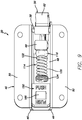
- Detent mechanism 114 includes an adjustable biasing mechanism 118 having a resilient biasing member 120, such as a helical coil spring, a plunger 122 and a plug or base member 124.
- Biasing member 120 extends between a first end 126 and a second end 128 generally concentrically about axis 110.
- Plunger 120 includes a head 130 having a recess 132 configured to receive a portion of detent member 116.
- Plunger 120 also includes a generally cylindrical stem extending from head 130 along axis 110. Stem 134 extends within second end 128 of biasing member 124.
- Base member 124 includes a head 138 and a stem 140 that extends within first end 126 of biasing member 120.
- biasing member 124 engages an interior surface of head 138 of base member 124
- second end 128 of biasing member 120 engages an interior surface of head 130 of plunger 122.
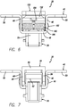
- Biasing member 120 resiliently biases plunger 122 into engagement with detent member 116 and thereby resiliently biases detent member 116 toward internal wall 90 of handle 78 and into detent 72 of bolt 56 as shown in Fig. 8 .
- the outer circumferential surface of head 138 of base member 124 threadably engages threads in cylindrical chamber 96 such that selective rotation of base member 124 about axis 110 will move base member 124 along axis 110 in a desired direction to compress or expand biasing member 120 to a desired extent such that biasing member 120 applies a desired force to detent member 116 for engagement with detent 72.
- detent member 116 When detent member 116 is in an extended position as shown in Fig. 8 , a portion of detent member 116 projects outwardly from aperture 92 of internal wall 90 and is located within detent 72 of arm 64 of bolt 56 to inhibit pivotal movement of belt 56 with respect to handle 74. Detent member 116 thereby releasably locks bolt 56 to handle 78 such that bolt 56 and handle 78 will conjointly pivot with one another about axis 60. However, when a sufficiently large force as applied to engagement member 62 of bolt 56 in a generally downward direction is viewed in Fig.
- the retention force with which biasing member 120 presses detent member 116 into detent 72 of bolt 56 may be overcome, such that arm 64 of bolt 56 presses detent member 116 toward base member 124 and first end 80 of handle 78 along axis 110 and compresses biasing member 122, such that bolt 56 may rotate in a generally clockwise direction about axis 60 with respect to handle 78 and bracket 40.
- bolt 56 may pivot about axis 60 with respect to mounting bracket 40 and handle 78 to a retracted position as shown in Figs. 18-19 .
- Outer surface 70 of arm 64 slides along detent member 116 as bolt 56 pivots about axis 60 between the retracted position as shown in Fig.
- Bolt 56 may be manually returned to the position as shown in Fig. 8 with respect to handle 78 by pressing downwardly on second end 68 of arm 64 to pivot bolt 56 in a counter-clockwise direction about axis 60 with respect to handle 78 until detent member 116 is located within detent 72 of bolt 56.
- Latch mechanism 20 also includes a trigger 150 that extends between a first end 152 and a second end 154.
- Trigger 150 includes a body 156 and an arm 158 that extends downwardly from the bottom end of body 156.
- a distal end of arm 158 includes a bore 160.
- a pin 162 having a central axis 164 extends through bore 160. The ends of pin 162 are coupled to respective side walls 46 of mounting bracket 40.
- Trigger 150 is located between side walls 46 of mounting bracket 40 and is pivotally coupled to mounting bracket 40 by pin 162 such that trigger 150 is pivotal with respect to mounting bracket 40 about axis 164.
- Axis 164 is spaced apart from and generally parallel to axis 58 of pin 60.
- Body 156 of trigger 150 includes an inclined slot 166 that is open at the top surface of body 156. Slot 166 is adapted to receive a tool, such as the tip of the screw driver, to assist in manually pivoting trigger 150 from a retracted position as shown in Figs. 1 and 8 in a counter-clockwise direction about axis 164 to an extended position as shown in Figs. 16 and 17 .
- Body 156 of trigger 150 includes a locking member 170 having a bottom surface 172 adapted to engage engagement surface 106 of retention members 104 of handle 78 when handle 78 is in the retracted position and trigger 150 is in the retracted position as shown in Figs. 3 and 8 , such that locking member 170 prevents pivotal movement of handle 78 about axis 68 in a generally clockwise direction with respect to mounting bracket 40 when a force is applied to engagement member 62 of bolt 56.
- Latch mechanism 20 includes a resilient biasing member 180, such as coil torsion spring.
- a pin 182 extends between and is coupled to side walls 46 of mounting bracket 40 and couples biasing member 180 to bracket 40.
- Biasing member 180 includes a first end 184 that is in biased engagement with a bottom surface of body 156 adjacent first end 152 of trigger 150 and a second end 186 that is in biased engagement with bottom wall 48 of mounting bracket 40.
- Biasing member 180 may be wrapped around pin 182.
- Biasing member 180 resiliently biases trigger 158 in a generally clock-wise direction about axis 164 from the extended position of trigger 150 as shown in Figs. 16 and 17 toward the retracted position of trigger 150 as shown in Fig. 3 .
- Trigger 150 is selectively manually pivotal from the retracted position as shown in Figs. 3 and 8 , wherein trigger 150 locks handle 178 in the retracted position with respect to mounting bracket 40, toward an extended position as shown in Figs. 16 and 17 wherein locking member 170 of trigger 150 is released from retention members 104 of handle 78, such that handle 78 and bolt 56 may conjointly pivot about axis 60 from their retracted positions toward their extended positions whereupon bolt 56 is released from second member 24. First member 22 may then be removed from, or repositioned with respect to, second member 24.
- the biasing member 180 When trigger 150 is manually released, the biasing member 180 will resiliently bias trigger 150 from the extended position to the retracted position.
- the handle 78 and bolt 56 When the handle 178 and bolt 56 are in the extended positions, the handle 78 and bolt 56 may be manually pivoted in a generally counter-clockwise direction about axis 60 by manually pressing second end 80 of handle 78 toward the retracted position.
- biasing surfaces 108 of retention members 104 will engage second end 154 of trigger 150 and will pivot trigger 150 in a counter-clockwise direction about axis 164 until retention members 104 pass by locking member 170 of trigger 150.
- Biasing member 180 then pivots trigger 150 in a clockwise direction about axis 162 such that locking member 170 of trigger 150 engages retention members 104 of handle 78 to thereby releasably lock handle 74 in the retracted position.
- Arm 64 of bolt 56 will extend and pass through aperture 88 in top wall 86 of handle 78 as bolt 56 pivots in a clockwise direction about axis 60 with respect to handle 78.
- First member 22 may be automatically removed from, or repositioned with respect to, second member 24 as a result of the excess-pressure condition, thereby preventing or reducing damage that may otherwise be caused to first member 22 and second member 24.
- Bolt 56 may be manually reset to the retracted position with respect to handle 78 as shown in Fig. 8 by pressing downwardly on second end 68 of arm 64.
Landscapes
- Engineering & Computer Science (AREA)
- Structural Engineering (AREA)
- Mechanical Engineering (AREA)
- Clamps And Clips (AREA)
Claims (10)
- Mécanisme de verrou (20) pour verrouiller, de manière amovible, un premier élément (22) à un second élément (24), l'élément de verrou comprenant :un support de montage (40) adapté pour être couplé au premier élément ;une poignée ayant une première extrémité et une seconde extrémité couplées de manière pivotante au support de montage, la poignée (78, 178) pouvant pivoter autour d'un axe central (60), d'une position rétractée à une position étendue ;une gâchette (150) pour verrouiller sélectivement la poignée dans la position rétractée ;un boulon (56) couplé, de manière pivotante, au support de montage pour le mouvement pivotant par rapport à la poignée et par rapport au support de montage, d'une position rétractée à une position étendue, le boulon comprenant un élément de mise en prise adapté pour mettre en prise le second élément, caractérisé en ce que le mécanisme de verrou comprend en outre :
un mécanisme de détente (114) pour coupler, de manière amovible, le boulon à la poignée, de sorte que le boulon et la poignée peuvent pivoter conjointement par rapport au support de montage, moyennant quoi le mécanisme de détente libère le boulon afin de pivoter par rapport à la poignée, lorsqu'une force excessive est appliquée sur l'élément de mise en prise du boulon. - Mécanisme de verrou (20) selon la revendication 1, dans lequel le mécanisme de détente (114) comprend un élément de détente (116) et un mécanisme de sollicitation (118) ayant un élément de sollicitation résilient (120) sollicitant, de manière résiliente, l'élément de détente (116) dans un évidement (72) du boulon (56).
- Mécanisme de verrou (20) selon la revendication 2, dans lequel le mécanisme de sollicitation (118) est ajustable.
- Mécanisme de verrou (20) selon les revendications 2 ou 3, dans lequel l'élément de sollicitation est un ressort hélicoïdal.
- Mécanisme de verrou selon l'une des revendications 2 à 4, dans lequel l'élément de détente (116) est une bille.
- Mécanisme de verrou selon l'une des revendications 2 à 5, dans lequel le mécanisme de sollicitation comprend un piston plongeur (122) ayant un évidement (132) configuré pour recevoir une partie de l'élément de détente (116).
- Procédé pour verrouiller, de manière amovible, un premier élément (22) à un second élément (24), le procédé comprenant les étapes consistant à :prévoir un mécanisme de verrou (20) comprenant un support de montage adapté pour être couplé au premier élément; une poignée (78, 178) ayant une première extrémité et une seconde extrémité couplées, de manière pivotante, au support de montage, la poignée (78, 178) pouvant pivoter d'une position rétractée à une position étendue, une gâchette pour verrouiller sélectivement la poignée dans la position rétractée, un boulon couplé, de manière pivotante, au support de montage (40) pour le mouvement pivotant par rapport à la poignée et par rapport au support de montage, d'une position rétractée à une position étendue, le boulon comprenant un élément de mise en prise adapté pour mettre en prise le second élément, et un mécanisme de détente (114) pour coupler, de manière amovible, le boulon à la poignée, de sorte que le boulon et la poignée peuvent pivoter conjointement par rapport au support de montage, libérant le boulon pour pivoter par rapport à la poignée lorsqu'une force excessive est appliquée sur l'élément de mise en prise du boulon ;faire pivoter la poignée (78, 178) et le boulon (56) conjointement l'un par rapport à l'autre, de leurs positions rétractées à leurs positions étendues pour libérer le boulon du second élément.
- Procédé selon la revendication 7, dans lequel l'étape consistant à libérer le boulon pour pivoter par rapport à la poignée lorsqu'une force excessive est appliquée, comprend l'étape consistant à déplacer l'élément de détente (116) dans une direction à distance du boulon (56).
- Procédé selon la revendication 7 ou 8, dans lequel la force excessive est appliquée pour faire pivoter le boulon (56).
- Procédé selon l'une des revendications 7 à 9, dans lequel le mécanisme de détente (114) comprend un élément de détente (116) et un mécanisme de sollicitation (118), lorsque le mécanisme de sollicitation comprend un piston plongeur (122) ayant un évidement (132) configuré pour recevoir une partie de l'élément de détente (116).
Applications Claiming Priority (2)
| Application Number | Priority Date | Filing Date | Title |
|---|---|---|---|
| US26680309P | 2009-12-04 | 2009-12-04 | |
| PCT/US2010/058957 WO2011069103A1 (fr) | 2009-12-04 | 2010-12-03 | Mécanisme de verrou détendeur de pression |
Publications (3)
| Publication Number | Publication Date |
|---|---|
| EP2507452A1 EP2507452A1 (fr) | 2012-10-10 |
| EP2507452A4 EP2507452A4 (fr) | 2017-03-22 |
| EP2507452B1 true EP2507452B1 (fr) | 2018-09-12 |
Family
ID=44115322
Family Applications (1)
| Application Number | Title | Priority Date | Filing Date |
|---|---|---|---|
| EP10835213.9A Active EP2507452B1 (fr) | 2009-12-04 | 2010-12-03 | Mécanisme de verrou détendeur de pression |
Country Status (4)
| Country | Link |
|---|---|
| US (1) | US9169678B2 (fr) |
| EP (1) | EP2507452B1 (fr) |
| ES (1) | ES2693294T3 (fr) |
| WO (1) | WO2011069103A1 (fr) |
Cited By (2)
| Publication number | Priority date | Publication date | Assignee | Title |
|---|---|---|---|---|
| DE102020205373A1 (de) | 2020-04-28 | 2021-10-28 | Sacs Aerospace Gmbh | Verriegelungseinrichtung |
| US20220042348A1 (en) * | 2020-08-07 | 2022-02-10 | Sacs Aerospace Gmbh | Latch |
Families Citing this family (43)
| Publication number | Priority date | Publication date | Assignee | Title |
|---|---|---|---|---|
| US8876230B2 (en) * | 2011-09-24 | 2014-11-04 | Hardware Resources, Inc. | Durable drawer retainer apparatus and method of use |
| HUE033299T2 (en) | 2014-02-16 | 2017-11-28 | Qrp Inc | Press release latch |
| ES2716095T3 (es) | 2014-02-18 | 2019-06-10 | Hartwell Corp | Pestillo de canal accionado por una herramienta |
| DE102014004911B4 (de) * | 2014-04-07 | 2017-03-09 | Sascha Shuxia Zhu | Tür- oder Fensterelement mit Griff und integriertem Druckausgleichsmechanismus, Verfahren zur Herstellung eines Tür- oder Fensterelements und Verwendung des Tür- oder Fensterelements |
| US9752358B2 (en) * | 2014-05-23 | 2017-09-05 | Aviation Technical Service, Inc. | Cargo door handle |
| WO2016040501A1 (fr) | 2014-09-09 | 2016-03-17 | Hartwell Corporation | Serrure de détection de chape |
| CA3062203C (fr) * | 2015-08-04 | 2023-04-25 | Arconic Inc. | Loquet detendeur de pression |
| ES2709624T3 (es) * | 2015-08-26 | 2019-04-17 | Arconic Inc | Cierre de alivio de presión ajustable |
| US10760304B2 (en) * | 2015-09-01 | 2020-09-01 | Howmet Aerospace Inc. | Adjustable hook latch |
| EP3322639B1 (fr) | 2016-01-21 | 2019-03-27 | Arconic Inc. | Verrou à cliquet |
| WO2017218416A1 (fr) | 2016-06-13 | 2017-12-21 | Arconic Inc. | Système de verrouillage rotatif |
| AU201717615S (en) | 2017-06-12 | 2018-01-15 | Yeti Coolers | Container |
| US11685573B2 (en) | 2017-06-12 | 2023-06-27 | Yeti Coolers, Llc | Carry strap for container |
| USD872485S1 (en) | 2017-06-12 | 2020-01-14 | Yeti Coolers, Llc | Container |
| USD828029S1 (en) | 2017-06-12 | 2018-09-11 | Yeti Coolers, Llc | Container |
| WO2018231826A1 (fr) | 2017-06-12 | 2018-12-20 | Yeti Coolers, Llc | Contenant et système de verrouillage |
| US12108853B2 (en) | 2019-01-06 | 2024-10-08 | Yeti Coolers, Llc | Luggage system |
| USD869160S1 (en) | 2017-06-12 | 2019-12-10 | Yeti Coolers, Llc | Container |
| USD873020S1 (en) | 2017-06-12 | 2020-01-21 | Yeti Coolers, Llc | Container |
| USD840150S1 (en) | 2017-06-12 | 2019-02-12 | Yeti Coolers, Llc | Container |
| USD838984S1 (en) | 2017-06-12 | 2019-01-29 | Yeti Coolers, Llc | Container |
| USD828028S1 (en) | 2017-06-12 | 2018-09-11 | Yeti Coolers, Llc | Container |
| USD872478S1 (en) | 2017-06-12 | 2020-01-14 | Yeti Coolers, Llc | Container |
| US11976498B2 (en) | 2017-06-12 | 2024-05-07 | Yeti Coolers, Llc | Container and latching system |
| USD838983S1 (en) | 2017-06-12 | 2019-01-29 | Yeti Coolers, Llc | Container |
| CN109356451A (zh) * | 2018-11-23 | 2019-02-19 | 珠海格力电器股份有限公司 | 一种门把手控制方法、装置、门把手、烤箱及存储介质 |
| USD907445S1 (en) | 2018-12-11 | 2021-01-12 | Yeti Coolers, Llc | Container accessories |
| USD904829S1 (en) | 2018-12-11 | 2020-12-15 | Yeti Coolers, Llc | Container accessories |
| US12225993B2 (en) | 2019-01-06 | 2025-02-18 | Yeti Coolers, Llc | Luggage system |
| MX2021008199A (es) | 2019-01-06 | 2021-11-12 | Yeti Coolers Llc | Sistema de equipaje. |
| US11530557B2 (en) * | 2019-10-11 | 2022-12-20 | Hartwell Corporation | Dual switch rotary latch |
| FR3108353B1 (fr) * | 2020-03-17 | 2022-03-25 | Lisi Aerospace | Verrou pour panneau d’aéronef |
| USD963344S1 (en) | 2020-06-30 | 2022-09-13 | Yeti Coolers, Llc | Luggage |
| USD954436S1 (en) | 2020-06-30 | 2022-06-14 | Yeti Coolers, Llc | Luggage |
| USD951643S1 (en) | 2020-06-30 | 2022-05-17 | Yeti Coolers, Llc | Luggage |
| USD961926S1 (en) | 2020-06-30 | 2022-08-30 | Yeti Coolers, Llc | Luggage |
| USD960648S1 (en) | 2020-12-16 | 2022-08-16 | Yeti Coolers, Llc | Container accessory |
| USD985937S1 (en) | 2020-12-16 | 2023-05-16 | Yeti Coolers, Llc | Container |
| USD994438S1 (en) | 2020-12-16 | 2023-08-08 | Yeti Coolers, Llc | Container |
| US11780553B2 (en) * | 2021-03-23 | 2023-10-10 | The Boeing Company | Latch assembly and aircraft having same |
| US12221219B2 (en) * | 2021-12-22 | 2025-02-11 | Rohr, Inc. | Pressure relief door assembly with temperature-actuated lock |
| US12473761B2 (en) * | 2023-01-19 | 2025-11-18 | Qrp, Inc. | Pressure-release latch with tension calibration |
| US12448140B2 (en) * | 2023-05-01 | 2025-10-21 | Rohr, Inc. | Pressure relief latch |
Family Cites Families (12)
| Publication number | Priority date | Publication date | Assignee | Title |
|---|---|---|---|---|
| US4365831A (en) * | 1980-04-04 | 1982-12-28 | Hartwell Corporation | Channel latch |
| US4602812A (en) * | 1983-05-20 | 1986-07-29 | Hartwell Corporation | Adjustable double hook latch |
| US4911485A (en) * | 1989-01-30 | 1990-03-27 | The Hartwell Corporation | Latch structure |
| US5638709A (en) * | 1994-04-25 | 1997-06-17 | Clavin; Timothy J. | Trigger latch |
| US5765883A (en) | 1995-07-14 | 1998-06-16 | Hartwell Corporation | Adjustable pressure relief latch |
| US6513841B1 (en) * | 2000-10-10 | 2003-02-04 | Hartwell Corporation | Blowout latch |
| US6755448B2 (en) * | 2001-06-20 | 2004-06-29 | Hartwell Corporation | Blowout latch |
| US7131672B2 (en) | 2002-05-03 | 2006-11-07 | Hartwell Corporation | Latch mechanism |
| US6606889B1 (en) * | 2002-05-29 | 2003-08-19 | Fastec Industrial Corp. | Pivot latch |
| US6913297B2 (en) * | 2003-10-27 | 2005-07-05 | Hartwell Corporation | Rotary latch mechanism |
| US7185926B2 (en) * | 2005-03-25 | 2007-03-06 | Hartwell Corporation | Preloaded latch mechanism |
| US8113551B2 (en) * | 2007-06-13 | 2012-02-14 | Avibank Manufacturing, Inc. | Radome latch and keeper |
-
2010
- 2010-12-03 US US13/513,631 patent/US9169678B2/en active Active
- 2010-12-03 WO PCT/US2010/058957 patent/WO2011069103A1/fr not_active Ceased
- 2010-12-03 EP EP10835213.9A patent/EP2507452B1/fr active Active
- 2010-12-03 ES ES10835213.9T patent/ES2693294T3/es active Active
Non-Patent Citations (1)
| Title |
|---|
| None * |
Cited By (3)
| Publication number | Priority date | Publication date | Assignee | Title |
|---|---|---|---|---|
| DE102020205373A1 (de) | 2020-04-28 | 2021-10-28 | Sacs Aerospace Gmbh | Verriegelungseinrichtung |
| US20220042348A1 (en) * | 2020-08-07 | 2022-02-10 | Sacs Aerospace Gmbh | Latch |
| US12559970B2 (en) * | 2020-08-07 | 2026-02-24 | Sacs Aerospace Gmbh | Latch |
Also Published As
| Publication number | Publication date |
|---|---|
| EP2507452A4 (fr) | 2017-03-22 |
| WO2011069103A1 (fr) | 2011-06-09 |
| ES2693294T3 (es) | 2018-12-10 |
| EP2507452A1 (fr) | 2012-10-10 |
| US20120242096A1 (en) | 2012-09-27 |
| US9169678B2 (en) | 2015-10-27 |
Similar Documents
| Publication | Publication Date | Title |
|---|---|---|
| EP2507452B1 (fr) | Mécanisme de verrou détendeur de pression | |
| CN100526585C (zh) | 压紧闩锁机构 | |
| EP2663707B1 (fr) | Mécanisme de verrouillage à détente de pression | |
| US4671089A (en) | Door latch and deadbolt assembly | |
| US8864185B2 (en) | Latch with adjustable handle | |
| US7185926B2 (en) | Preloaded latch mechanism | |
| CN109940663B (zh) | 具有锁定机构的折叠刀 | |
| US8550437B2 (en) | Tool with working and positioning devices | |
| US11002046B2 (en) | High offset hook latch | |
| US6854304B2 (en) | Paddle lock | |
| EP3341544B1 (fr) | Verrou de détente ajustable | |
| EP1811109A2 (fr) | Dispositif de verrouillage d'une serrure de sécurité pour un ordinateur portable | |
| US20160230423A1 (en) | Dogging security indicator for exit device | |
| US20050257582A1 (en) | Door latch with adjustable latch element | |
| US20110239712A1 (en) | Adjustable Driving Mechanism for Panic Exit Door Lock | |
| EP3331760B1 (fr) | Loquet détendeur de pression | |
| US20050008458A1 (en) | Biased fastening system | |
| US9624700B2 (en) | Paddle latch | |
| JP2023070024A (ja) | 腕時計リストレット用のインサート | |
| US11041331B2 (en) | Latch having tool recess in trigger | |
| CN205819536U (zh) | 一种按钮式限位装置以及具有该装置的直升机窗户 | |
| EP2956331B1 (fr) | Siège de véhicule avec unité de verrouillage | |
| WO1997036715A1 (fr) | Cle a autoserrage | |
| CN220949010U (zh) | 用于包装箱框架的锁定装置 | |
| CN223793998U (zh) | 一种锁扣、锁具及箱体结构 |
Legal Events
| Date | Code | Title | Description |
|---|---|---|---|
| PUAI | Public reference made under article 153(3) epc to a published international application that has entered the european phase |
Free format text: ORIGINAL CODE: 0009012 |
|
| 17P | Request for examination filed |
Effective date: 20120703 |
|
| AK | Designated contracting states |
Kind code of ref document: A1 Designated state(s): AL AT BE BG CH CY CZ DE DK EE ES FI FR GB GR HR HU IE IS IT LI LT LU LV MC MK MT NL NO PL PT RO RS SE SI SK SM TR |
|
| DAX | Request for extension of the european patent (deleted) | ||
| RA4 | Supplementary search report drawn up and despatched (corrected) |
Effective date: 20170221 |
|
| RIC1 | Information provided on ipc code assigned before grant |
Ipc: E05C 19/12 20060101AFI20170215BHEP |
|
| GRAJ | Information related to disapproval of communication of intention to grant by the applicant or resumption of examination proceedings by the epo deleted |
Free format text: ORIGINAL CODE: EPIDOSDIGR1 |
|
| GRAP | Despatch of communication of intention to grant a patent |
Free format text: ORIGINAL CODE: EPIDOSNIGR1 |
|
| INTG | Intention to grant announced |
Effective date: 20180329 |
|
| GRAS | Grant fee paid |
Free format text: ORIGINAL CODE: EPIDOSNIGR3 |
|
| GRAA | (expected) grant |
Free format text: ORIGINAL CODE: 0009210 |
|
| AK | Designated contracting states |
Kind code of ref document: B1 Designated state(s): AL AT BE BG CH CY CZ DE DK EE ES FI FR GB GR HR HU IE IS IT LI LT LU LV MC MK MT NL NO PL PT RO RS SE SI SK SM TR |
|
| REG | Reference to a national code |
Ref country code: GB Ref legal event code: FG4D |
|
| REG | Reference to a national code |
Ref country code: CH Ref legal event code: EP |
|
| REG | Reference to a national code |
Ref country code: DE Ref legal event code: R082 Ref document number: 602010053603 Country of ref document: DE Representative=s name: LAVOIX MUNICH, DE |
|
| REG | Reference to a national code |
Ref country code: IE Ref legal event code: FG4D |
|
| REG | Reference to a national code |
Ref country code: DE Ref legal event code: R096 Ref document number: 602010053603 Country of ref document: DE |
|
| REG | Reference to a national code |
Ref country code: AT Ref legal event code: REF Ref document number: 1040779 Country of ref document: AT Kind code of ref document: T Effective date: 20181015 |
|
| REG | Reference to a national code |
Ref country code: ES Ref legal event code: FG2A Ref document number: 2693294 Country of ref document: ES Kind code of ref document: T3 Effective date: 20181210 |
|
| REG | Reference to a national code |
Ref country code: NL Ref legal event code: MP Effective date: 20180912 |
|
| REG | Reference to a national code |
Ref country code: LT Ref legal event code: MG4D |
|
| PG25 | Lapsed in a contracting state [announced via postgrant information from national office to epo] |
Ref country code: LT Free format text: LAPSE BECAUSE OF FAILURE TO SUBMIT A TRANSLATION OF THE DESCRIPTION OR TO PAY THE FEE WITHIN THE PRESCRIBED TIME-LIMIT Effective date: 20180912 Ref country code: RS Free format text: LAPSE BECAUSE OF FAILURE TO SUBMIT A TRANSLATION OF THE DESCRIPTION OR TO PAY THE FEE WITHIN THE PRESCRIBED TIME-LIMIT Effective date: 20180912 Ref country code: NO Free format text: LAPSE BECAUSE OF FAILURE TO SUBMIT A TRANSLATION OF THE DESCRIPTION OR TO PAY THE FEE WITHIN THE PRESCRIBED TIME-LIMIT Effective date: 20181212 Ref country code: SE Free format text: LAPSE BECAUSE OF FAILURE TO SUBMIT A TRANSLATION OF THE DESCRIPTION OR TO PAY THE FEE WITHIN THE PRESCRIBED TIME-LIMIT Effective date: 20180912 Ref country code: GR Free format text: LAPSE BECAUSE OF FAILURE TO SUBMIT A TRANSLATION OF THE DESCRIPTION OR TO PAY THE FEE WITHIN THE PRESCRIBED TIME-LIMIT Effective date: 20181213 Ref country code: FI Free format text: LAPSE BECAUSE OF FAILURE TO SUBMIT A TRANSLATION OF THE DESCRIPTION OR TO PAY THE FEE WITHIN THE PRESCRIBED TIME-LIMIT Effective date: 20180912 Ref country code: BG Free format text: LAPSE BECAUSE OF FAILURE TO SUBMIT A TRANSLATION OF THE DESCRIPTION OR TO PAY THE FEE WITHIN THE PRESCRIBED TIME-LIMIT Effective date: 20181212 |
|
| PG25 | Lapsed in a contracting state [announced via postgrant information from national office to epo] |
Ref country code: HR Free format text: LAPSE BECAUSE OF FAILURE TO SUBMIT A TRANSLATION OF THE DESCRIPTION OR TO PAY THE FEE WITHIN THE PRESCRIBED TIME-LIMIT Effective date: 20180912 Ref country code: LV Free format text: LAPSE BECAUSE OF FAILURE TO SUBMIT A TRANSLATION OF THE DESCRIPTION OR TO PAY THE FEE WITHIN THE PRESCRIBED TIME-LIMIT Effective date: 20180912 Ref country code: AL Free format text: LAPSE BECAUSE OF FAILURE TO SUBMIT A TRANSLATION OF THE DESCRIPTION OR TO PAY THE FEE WITHIN THE PRESCRIBED TIME-LIMIT Effective date: 20180912 |
|
| REG | Reference to a national code |
Ref country code: AT Ref legal event code: MK05 Ref document number: 1040779 Country of ref document: AT Kind code of ref document: T Effective date: 20180912 |
|
| PG25 | Lapsed in a contracting state [announced via postgrant information from national office to epo] |
Ref country code: CZ Free format text: LAPSE BECAUSE OF FAILURE TO SUBMIT A TRANSLATION OF THE DESCRIPTION OR TO PAY THE FEE WITHIN THE PRESCRIBED TIME-LIMIT Effective date: 20180912 Ref country code: RO Free format text: LAPSE BECAUSE OF FAILURE TO SUBMIT A TRANSLATION OF THE DESCRIPTION OR TO PAY THE FEE WITHIN THE PRESCRIBED TIME-LIMIT Effective date: 20180912 Ref country code: IT Free format text: LAPSE BECAUSE OF FAILURE TO SUBMIT A TRANSLATION OF THE DESCRIPTION OR TO PAY THE FEE WITHIN THE PRESCRIBED TIME-LIMIT Effective date: 20180912 Ref country code: AT Free format text: LAPSE BECAUSE OF FAILURE TO SUBMIT A TRANSLATION OF THE DESCRIPTION OR TO PAY THE FEE WITHIN THE PRESCRIBED TIME-LIMIT Effective date: 20180912 Ref country code: NL Free format text: LAPSE BECAUSE OF FAILURE TO SUBMIT A TRANSLATION OF THE DESCRIPTION OR TO PAY THE FEE WITHIN THE PRESCRIBED TIME-LIMIT Effective date: 20180912 Ref country code: EE Free format text: LAPSE BECAUSE OF FAILURE TO SUBMIT A TRANSLATION OF THE DESCRIPTION OR TO PAY THE FEE WITHIN THE PRESCRIBED TIME-LIMIT Effective date: 20180912 Ref country code: PL Free format text: LAPSE BECAUSE OF FAILURE TO SUBMIT A TRANSLATION OF THE DESCRIPTION OR TO PAY THE FEE WITHIN THE PRESCRIBED TIME-LIMIT Effective date: 20180912 Ref country code: IS Free format text: LAPSE BECAUSE OF FAILURE TO SUBMIT A TRANSLATION OF THE DESCRIPTION OR TO PAY THE FEE WITHIN THE PRESCRIBED TIME-LIMIT Effective date: 20190112 |
|
| PG25 | Lapsed in a contracting state [announced via postgrant information from national office to epo] |
Ref country code: SK Free format text: LAPSE BECAUSE OF FAILURE TO SUBMIT A TRANSLATION OF THE DESCRIPTION OR TO PAY THE FEE WITHIN THE PRESCRIBED TIME-LIMIT Effective date: 20180912 Ref country code: PT Free format text: LAPSE BECAUSE OF FAILURE TO SUBMIT A TRANSLATION OF THE DESCRIPTION OR TO PAY THE FEE WITHIN THE PRESCRIBED TIME-LIMIT Effective date: 20190112 Ref country code: SM Free format text: LAPSE BECAUSE OF FAILURE TO SUBMIT A TRANSLATION OF THE DESCRIPTION OR TO PAY THE FEE WITHIN THE PRESCRIBED TIME-LIMIT Effective date: 20180912 |
|
| REG | Reference to a national code |
Ref country code: DE Ref legal event code: R097 Ref document number: 602010053603 Country of ref document: DE |
|
| PLBE | No opposition filed within time limit |
Free format text: ORIGINAL CODE: 0009261 |
|
| STAA | Information on the status of an ep patent application or granted ep patent |
Free format text: STATUS: NO OPPOSITION FILED WITHIN TIME LIMIT |
|
| PG25 | Lapsed in a contracting state [announced via postgrant information from national office to epo] |
Ref country code: DK Free format text: LAPSE BECAUSE OF FAILURE TO SUBMIT A TRANSLATION OF THE DESCRIPTION OR TO PAY THE FEE WITHIN THE PRESCRIBED TIME-LIMIT Effective date: 20180912 |
|
| REG | Reference to a national code |
Ref country code: CH Ref legal event code: PL |
|
| 26N | No opposition filed |
Effective date: 20190613 |
|
| PG25 | Lapsed in a contracting state [announced via postgrant information from national office to epo] |
Ref country code: SI Free format text: LAPSE BECAUSE OF FAILURE TO SUBMIT A TRANSLATION OF THE DESCRIPTION OR TO PAY THE FEE WITHIN THE PRESCRIBED TIME-LIMIT Effective date: 20180912 Ref country code: LU Free format text: LAPSE BECAUSE OF NON-PAYMENT OF DUE FEES Effective date: 20181203 Ref country code: MC Free format text: LAPSE BECAUSE OF FAILURE TO SUBMIT A TRANSLATION OF THE DESCRIPTION OR TO PAY THE FEE WITHIN THE PRESCRIBED TIME-LIMIT Effective date: 20180912 |
|
| REG | Reference to a national code |
Ref country code: IE Ref legal event code: MM4A |
|
| REG | Reference to a national code |
Ref country code: BE Ref legal event code: MM Effective date: 20181231 |
|
| PG25 | Lapsed in a contracting state [announced via postgrant information from national office to epo] |
Ref country code: IE Free format text: LAPSE BECAUSE OF NON-PAYMENT OF DUE FEES Effective date: 20181203 |
|
| PG25 | Lapsed in a contracting state [announced via postgrant information from national office to epo] |
Ref country code: BE Free format text: LAPSE BECAUSE OF NON-PAYMENT OF DUE FEES Effective date: 20181231 |
|
| PG25 | Lapsed in a contracting state [announced via postgrant information from national office to epo] |
Ref country code: LI Free format text: LAPSE BECAUSE OF NON-PAYMENT OF DUE FEES Effective date: 20181231 Ref country code: CH Free format text: LAPSE BECAUSE OF NON-PAYMENT OF DUE FEES Effective date: 20181231 |
|
| PG25 | Lapsed in a contracting state [announced via postgrant information from national office to epo] |
Ref country code: MT Free format text: LAPSE BECAUSE OF NON-PAYMENT OF DUE FEES Effective date: 20181203 |
|
| PG25 | Lapsed in a contracting state [announced via postgrant information from national office to epo] |
Ref country code: TR Free format text: LAPSE BECAUSE OF FAILURE TO SUBMIT A TRANSLATION OF THE DESCRIPTION OR TO PAY THE FEE WITHIN THE PRESCRIBED TIME-LIMIT Effective date: 20180912 |
|
| PG25 | Lapsed in a contracting state [announced via postgrant information from national office to epo] |
Ref country code: MK Free format text: LAPSE BECAUSE OF NON-PAYMENT OF DUE FEES Effective date: 20180912 Ref country code: CY Free format text: LAPSE BECAUSE OF FAILURE TO SUBMIT A TRANSLATION OF THE DESCRIPTION OR TO PAY THE FEE WITHIN THE PRESCRIBED TIME-LIMIT Effective date: 20180912 Ref country code: HU Free format text: LAPSE BECAUSE OF FAILURE TO SUBMIT A TRANSLATION OF THE DESCRIPTION OR TO PAY THE FEE WITHIN THE PRESCRIBED TIME-LIMIT; INVALID AB INITIO Effective date: 20101203 |
|
| PGFP | Annual fee paid to national office [announced via postgrant information from national office to epo] |
Ref country code: GB Payment date: 20251229 Year of fee payment: 16 |
|
| PGFP | Annual fee paid to national office [announced via postgrant information from national office to epo] |
Ref country code: FR Payment date: 20251226 Year of fee payment: 16 |
|
| PGFP | Annual fee paid to national office [announced via postgrant information from national office to epo] |
Ref country code: ES Payment date: 20260102 Year of fee payment: 16 |
|
| PGFP | Annual fee paid to national office [announced via postgrant information from national office to epo] |
Ref country code: DE Payment date: 20251229 Year of fee payment: 16 |