EP2507551B1 - Verfahren zur korrektur der verbrennungseinstellungen eines strahlungsrohr-brennkammernsatzes und vorrichtung zur umsetzung des verfahrens - Google Patents
Verfahren zur korrektur der verbrennungseinstellungen eines strahlungsrohr-brennkammernsatzes und vorrichtung zur umsetzung des verfahrens Download PDFInfo
- Publication number
- EP2507551B1 EP2507551B1 EP10790878.2A EP10790878A EP2507551B1 EP 2507551 B1 EP2507551 B1 EP 2507551B1 EP 10790878 A EP10790878 A EP 10790878A EP 2507551 B1 EP2507551 B1 EP 2507551B1
- Authority
- EP
- European Patent Office
- Prior art keywords
- combustion
- tubes
- fuel
- concentration
- chambers
- Prior art date
- Legal status (The legal status is an assumption and is not a legal conclusion. Google has not performed a legal analysis and makes no representation as to the accuracy of the status listed.)
- Active
Links
Images

Classifications
-
- F—MECHANICAL ENGINEERING; LIGHTING; HEATING; WEAPONS; BLASTING
- F23—COMBUSTION APPARATUS; COMBUSTION PROCESSES
- F23N—REGULATING OR CONTROLLING COMBUSTION
- F23N5/00—Systems for controlling combustion
- F23N5/003—Systems for controlling combustion using detectors sensitive to combustion gas properties
- F23N5/006—Systems for controlling combustion using detectors sensitive to combustion gas properties the detector being sensitive to oxygen
-
- F—MECHANICAL ENGINEERING; LIGHTING; HEATING; WEAPONS; BLASTING
- F23—COMBUSTION APPARATUS; COMBUSTION PROCESSES
- F23C—METHODS OR APPARATUS FOR COMBUSTION USING FLUID FUEL OR SOLID FUEL SUSPENDED IN A CARRIER GAS OR AIR
- F23C6/00—Combustion apparatus characterised by the combination of two or more combustion chambers or combustion zones, e.g. for staged combustion
- F23C6/02—Combustion apparatus characterised by the combination of two or more combustion chambers or combustion zones, e.g. for staged combustion in parallel arrangement
-
- F—MECHANICAL ENGINEERING; LIGHTING; HEATING; WEAPONS; BLASTING
- F23—COMBUSTION APPARATUS; COMBUSTION PROCESSES
- F23N—REGULATING OR CONTROLLING COMBUSTION
- F23N1/00—Regulating fuel supply
-
- F—MECHANICAL ENGINEERING; LIGHTING; HEATING; WEAPONS; BLASTING
- F23—COMBUSTION APPARATUS; COMBUSTION PROCESSES
- F23N—REGULATING OR CONTROLLING COMBUSTION
- F23N3/00—Regulating air supply or draught
-
- F—MECHANICAL ENGINEERING; LIGHTING; HEATING; WEAPONS; BLASTING
- F23—COMBUSTION APPARATUS; COMBUSTION PROCESSES
- F23N—REGULATING OR CONTROLLING COMBUSTION
- F23N5/00—Systems for controlling combustion
-
- F—MECHANICAL ENGINEERING; LIGHTING; HEATING; WEAPONS; BLASTING
- F23—COMBUSTION APPARATUS; COMBUSTION PROCESSES
- F23N—REGULATING OR CONTROLLING COMBUSTION
- F23N5/00—Systems for controlling combustion
- F23N5/003—Systems for controlling combustion using detectors sensitive to combustion gas properties
-
- F—MECHANICAL ENGINEERING; LIGHTING; HEATING; WEAPONS; BLASTING
- F23—COMBUSTION APPARATUS; COMBUSTION PROCESSES
- F23C—METHODS OR APPARATUS FOR COMBUSTION USING FLUID FUEL OR SOLID FUEL SUSPENDED IN A CARRIER GAS OR AIR
- F23C2201/00—Staged combustion
- F23C2201/20—Burner staging
-
- F—MECHANICAL ENGINEERING; LIGHTING; HEATING; WEAPONS; BLASTING
- F23—COMBUSTION APPARATUS; COMBUSTION PROCESSES
- F23C—METHODS OR APPARATUS FOR COMBUSTION USING FLUID FUEL OR SOLID FUEL SUSPENDED IN A CARRIER GAS OR AIR
- F23C2202/00—Fluegas recirculation
- F23C2202/20—Premixing fluegas with fuel
-
- F—MECHANICAL ENGINEERING; LIGHTING; HEATING; WEAPONS; BLASTING
- F23—COMBUSTION APPARATUS; COMBUSTION PROCESSES
- F23C—METHODS OR APPARATUS FOR COMBUSTION USING FLUID FUEL OR SOLID FUEL SUSPENDED IN A CARRIER GAS OR AIR
- F23C2202/00—Fluegas recirculation
- F23C2202/30—Premixing fluegas with combustion air
-
- F—MECHANICAL ENGINEERING; LIGHTING; HEATING; WEAPONS; BLASTING
- F23—COMBUSTION APPARATUS; COMBUSTION PROCESSES
- F23D—BURNERS
- F23D2203/00—Gaseous fuel burners
- F23D2203/002—Radiant burner mixing tubes
-
- F—MECHANICAL ENGINEERING; LIGHTING; HEATING; WEAPONS; BLASTING
- F23—COMBUSTION APPARATUS; COMBUSTION PROCESSES
- F23N—REGULATING OR CONTROLLING COMBUSTION
- F23N2237/00—Controlling
- F23N2237/02—Controlling two or more burners
Definitions
- the present invention relates to a method for adjusting the supply devices of a set of combustion combustion chambers fed with an oxidant and a fuel whose properties are variable.
- the present invention also relates to an installation for implementing such a method. It makes it possible to take into account the possible fluctuations of these properties so as to maintain the desired combustion quality.
- Many industrial heating equipment consists of a set of separate combustion chambers fed by a common oxidizer and fuel supply device. For example, in the iron and steel industry, this is the case of furnaces for continuous lines for treating metal strips, equipped with radiant tubes. In many cases, the oxidants or fuels used have variable properties over time.
- FR2712961 A particular process is proposed by FR2712961 . According to this method, a burner is adjusted by taking a given flow rate of fuel. burns this fuel in a dedicated chamber with a flow of air such that it leads to combustion in excess of air, and is measured in the flue gas complete fuel a magnitude reflecting the stoichiometric difference. This quantity is then used to determine the representative value of the combustion air flow rate regulator of the burner.
- This comburimeter device consists of a combustion tunnel, a burner and appropriate measuring means.
- This system has the disadvantage of implementing a specially constructed mini oven in which one burns an air / fuel mixture to proportions set to have an excess of air.
- This mini oven consumes fuel and must operate in excess of air.
- Combustion is carried out in this mini-oven on an operating point which may be remote from that of the installation to be regulated, for example as regards the power of the burner, the air / gas ratio, the temperature of the oven, and the containment of the flame.
- the exploitation of the results thus requires the use of mathematical correction formulas.
- This system also has the disadvantage of being dedicated exclusively to taking into account variations in fuel properties.
- the object of the invention is, above all, to improve the control of the combustion of a set of combustion chambers participating in a manufacturing process; in particular, the invention aims to improve the adjustment of a set of radiant tubes of a line of continuous treatment of metal strips.
- combustion chambers are of the same nature. The power of each of them can be variable but the technologies implemented are similar. The differences between these combustion chambers have no influence on the combustion parameters that we want to control.
- one of these tubes is used in the furnace laboratory as a reference tube. It participates in heating the band as all other tubes.
- This radiant tube is of a construction similar to that of the others tubes and is solicited in a manner representative of the operation of the other tubes which participate in the heating.
- the combustion products at the outlet of the radiant tube cooled by participating in the furnace heating process.
- a measuring apparatus is installed which provides information on the state of the combustion products after the tube. It is usually a gas analyzer allowing in particular to know for example the excess air and / or unburnt.
- control parameters of all the enclosures are adjusted so as to obtain the excess air and / or the rate of unburnt targeted.
- the concentration of nitrogen oxides can be regulated by adjusting the composition of the oxidant and / or the fuel, in particular by dilution with products of combustion.
- the thermal chambers consist of radiant tubes fed with proportions of gas different from those of the reference tube.
- the thermal chambers consist of radiant tubes, and a reference tube can be fed in a common manner with the other tubes, the regulating members being placed on common supply circuits to all the tubes.
- the radiant tubes are supplied in a manner distinct from the reference tube and have regulating means different from those of the reference tube, on different supply circuits, the regulating members of the tubes being controlled so that these tubes are fed with the same proportions of gas as the reference tube.
- the regulating members of the radiant tubes can be controlled so that these tubes are fed with proportions of gases different from those of the reference tube, in particular with a different excess of air.
- the invention is used as a combustion chamber standard equipment similar to the others, which participates in the process and whose setting is perfectly representative of the operation of all equipment. It allows, in particular, to control parameters that depend on the operating mode of the entire installation.
- the master parameter is the excess air measured by the oxygen concentration.
- the method according to the invention also makes it possible to regulate equipment operating in lack of air.
- the controlled parameter may be a compound representing one of the gases representative of this mode of combustion, present in large proportion in the fumes. It can be for example CO carbon monoxide.
- the reference tube is fed by fuel and fuel supply circuits equipped with regulating devices to adjust their proportion. It can also be powered by additional circuits, for example combustion fumes or oxygen.
- the analyzes carried out on the products of combustion at the outlet of the reference tube are taken into account to control the regulating elements of the supply circuits so as to reach the desired combustion quality.
- the reference tube is fed in a common way with the other tubes, that is to say when the regulating members are placed on supply circuits common to all the tubes, including the reference tube the other tubes benefit from this same setting.
- radiant tubes are supplied in a manner distinct from the reference tube, that is to say that they have regulating members on different supply circuits, these regulating members are controlled so that these tubes are fed with the same proportions of gas as the reference tube, or with a different proportion. If the two sets of radiant tubes are designed to have identical regulated parameters, for example an identical supply pressure, for a different operating power while maintaining the same proportion of gas, the regulated parameters of the reference tube are reproduced for the members of the supply circuits of the second set of tubes.
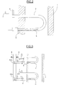
- a furnace 1 equipped with radiant tubes 2 for heating a metal strip 3, scrolling on unrepresented rollers.
- the heating is carried out under a protective atmosphere generally composed of a mixture of nitrogen and hydrogen.
- a protective atmosphere generally composed of a mixture of nitrogen and hydrogen.
- combustion is provided in a confined combustion chamber, separated from the laboratory oven by the tube. We then have indirect heating.
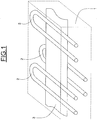
- a radiant tube 2 U-shaped U-shaped.
- the radiant tubes may have other shapes, for example I, P, double P or W.
- a burner 4 is located one end of the tube 2.
- the flame 5 propagates in the tube and releases its energy towards the walls of the tube which heats the laboratory and the band. As they travel through the tube, the fumes heat up on the walls of the tube.
- a heat recovery unit not shown, for preheating the combustion air.
- the fumes in spent parts are discharged to a manifold 6, connected to a chimney.
- An analyzer 7, implanted after the exit of the tube, allows the analysis of the products of combustion.
- FIG. 3 we can see, schematically shown, an embodiment of the fuel supply circuit and fuel of a set of U-shaped radiant tubes, including a reference tube 2r.
- the burners 4 are fed by an oxidizer supply system 8, with an FCVc control valve, and a fuel supply system 9, with an FCVf control valve.
- the automatic adjustment of the valves can be provided by a controller (not shown) which receives as input the information on the combustion parameters measured by the analyzer 7 at the output of the reference tube 2r.
- the controller provides, on outputs connected to the valve controls, setting instructions determined according to the input data.
- the furnace zone is equipped with radiant tubes 2 whose burners 4 are supplied in parallel by common oxidant and fuel networks.
- the variation in heat demand is managed by the operating times of the burners, that is to say for each burner the proportion of the opening time of its FCVc oxidizer valve and its FCVf fuel valve for a given time.
- each of the burners was previously set during commissioning for a known operating point by means of manual flow rate limiters 10.
- each of the burners was previously regulated by a singular device of limitation of flow.
- the operation of a tube chosen as a reference tube is the overall image of the operation of all the burners connected to the same supply systems.
- FCVc and FCVf valves causes a variation in the pressure of the oxidant Pc or the fuel pressure Pf making it possible to adjust the proportion of gases to the same for all the tubes.
- the measurements made by the analyzer 7 placed at the outlet of the reference tube may for example be limited to two parameters: the oxygen content, which represents the excess of oxidant, and the proportion of unburnt, the quantity of which may lead to Excess air corrections, especially at low temperatures.
- a set of four radiant tubes 2 is fed by oxidizing networks 8 and fuels 9 common to all four tubes by means of control valves FCVc and FCVf.
- a reference radiant tube 2i is fed separately with its own oxidizer supply system 8i regulated by a valve FCVci, and fuel 9i regulated by a valve FCVfi.
- the transmitters used on the reference tube 2i and the group of tubes 2 to be regulated exploit the same physical laws.
- a differential pressure transmitter can be used to measure a flow rate.
- each of the burners including that of the reference tube, was previously set for commissioning by a singular device for limiting the flow rate, in particular manual adjustment, so as to obtain the same oxidizer / fuel ratio on each burner.
- This adjustment is made under the same conditions for all the tubes, that is to say with the same quality of oxidant and fuel.
- the oxidant and fuel flow rates of the reference tube are adjusted to have the correct oxygen level in the flue gas according to the changes in the properties of the fuel and / or the oxidant.
- the analyzer 7 makes it possible to adjust the FCVci and FCVfi valves so as to obtain the targeted combustion quality in the reference tube.
- the corresponding operating point measured by the pressures Pci and Pfi, defines the setpoints Pc and Pf used to set the valves FCVc and FCVf.
- K is a constant
- Ivai expresses the signal of the representative measurement of the oxidant on the reference tube 2i
- Ivfi expresses the signal of the measurement representative of the fuel on the reference tube 2i
- Ivf expresses the signal of the representative measurement of the fuel on the group of tubes 2 to be regulated.
- An extension of this application is to control an installation whose composition of the oxidant is variable. This variation can be unintended, for example the composition of the air is dependent on the moisture content.
- This variation can be voluntary, for example by changing the oxygen content of the oxidizer.
- an oxygen enrichment can be achieved to increase the production of an oven, reduce fuel consumption or reduce CO2 emissions.
- Oxygen depletion can be achieved in order to modify the heat transfer, for example by lengthening the flame, or to reduce NOx emissions.
- a measurement of NOx in the flue gases of the reference tube will be used to regulate the dilution ratio of the oxidant.
- the invention makes it possible to adjust settings that may be different from that of the reference burner.
- the flame develops in a reference chamber similar to other speakers, and not in the open air.
- the combustion in an enclosure is strongly influenced by the geometry of it. This conditions the flame confinement, the nature of the gas flows, the recirculation of a part of the fumes and the temperature mapping in the enclosure. All these parameters affect the combustion, especially the flame temperature.
Landscapes
- Engineering & Computer Science (AREA)
- Chemical & Material Sciences (AREA)
- Combustion & Propulsion (AREA)
- Mechanical Engineering (AREA)
- General Engineering & Computer Science (AREA)
- Regulation And Control Of Combustion (AREA)
- Feeding And Controlling Fuel (AREA)
Claims (12)
- Verfahren zur in Echtzeit erfolgenden und kontinuierlichen Regelung einer Gruppe von durch Strahlungsrohre gebildeten thermischen Brennkammern (2, 2r, 2i) mit ähnlichen Merkmalen, welche durch dieselben Verbrennungsluft- (8) und Brennstoffnetze (9) gespeist werden, wobei bei dem Verfahren:- eine der Kammern (2, 2r, 2i) als Referenzkammer verwendet wird,- Verbrennungsparameter im Rauch am Auslass der Referenzkammer gemessen (7) werden,- die Regelparameter der Kammergruppe in Abhängigkeit von den am Auslass der Referenzkammer gemessenen Verbrennungsparametern eingestellt werden, insbesondere in Abhängigkeit von dem Verhältnis zwischen der Verbrennungsluft und dem Brennstoff und/oder der Zusammensetzung der Verbrennungsluft und/oder des Brennstoffs.
- Verfahren nach Anspruch 1, bei welchem die im Rauch am Auslass der Referenzkammer gemessenen Verbrennungsparameter zumindest die Sauerstoffkonzentration und/oder die Kohlendioxidkonzentration und/oder die Kohlenmonoxidkonzentration und/oder die Wasserstoffkonzentration und/oder den Gehalt an unverbrannten Stoffen und/oder die Stickoxidkonzentration umfassen.
- Verfahren nach Anspruch 2, bei welchem ein Luftüberschuss anhand der Sauerstoff- oder der Kohlendioxidkonzentration im Rauch am Auslass der Referenzkammer bestimmt wird.
- Verfahren nach Anspruch 2, bei welchem ein Luftmangel anhand der Konzentration von Kohlenmonoxid oder von Wasserstoff oder von unverbrannten Stoffen am Auslass der Referenzkammer bestimmt wird.
- Verfahren nach einem der Ansprüche 1 bis 3, bei welchem die Regelparameter der Kammergruppe derart eingestellt werden, dass der angestrebte Luftüberschuss und/oder der angestrebte Gehalt an unverbrannten Stoffen erreicht werden.
- Verfahren nach Anspruch 4, bei welchem die Regelparameter der Kammergruppe derart eingestellt werden, dass der angestrebte Luftmangel erreicht wird.
- Verfahren nach Anspruch 2, bei welchem die Stickoxidkonzentration geregelt wird, indem die Zusammensetzung der Verbrennungsluft und/oder des Brennstoffs insbesondere durch Verdünnung mit Verbrennungsprodukten eingestellt wird.
- Verfahren nach einem der vorhergehenden Ansprüche, bei welchem eines der Strahlungsrohre ein Referenzrohr bildet, und wobei den anderen Strahlungsrohren Gasmengenverhältnisse zugeführt werden, welche von demjenigen des Referenzrohrs verschieden sind.
- Anlage zur Durchführung eines Verfahrens nach einem der vorhergehenden Ansprüche, mit einer Gruppe von durch Strahlungsrohre gebildeten thermischen Brennkammern (2, 2r, 2i) mit ähnlichen Merkmalen, welche durch dieselben Verbrennungsluft- (8) und Brennstoffnetze (9) gespeist werden, wobei bei der Anlage:- eine der Kammern (2, 2r, 2i) als Referenzkammer verwendet wird,- Verbrennungsparametermesseinrichtungen (7) am Auslass der Referenzkammer angebracht sind, um die Verbrennungsparameter im Rauch am Auslass zu messen,- Regeleinrichtungen (FCVc, FCVf) vorgesehen sind, um die Regelparameter der Kammergruppe in Abhängigkeit von den am Auslass der Referenzkammer gemessenen Verbrennungsparametern einzustellen, insbesondere in Abhängigkeit von dem Verhältnis zwischen der Verbrennungsluft und dem Brennstoff und/oder der Zusammensetzung der Verbrennungsluft und/oder des Brennstoffs.
- Anlage nach Anspruch 9, bei welcher ein Referenzrohr (2r) gemeinsam mit den anderen Rohren gespeist wird, wobei die Regeleinrichtungen (FCVc, FCVf) in den der Rohrgruppe gemeinsamen Zuführkreisläufen (8, 9) angeordnet sind.
- Anlage nach Anspruch 9, bei welcher eines der Strahlungsrohre ein Referenzrohr (2i) bildet, und die anderen Strahlungsrohre auf eine von dem Referenzrohr (2i) verschiedene Weise gespeist werden und mit von denjenigen (FCVci, FCVfi) des Referenzrohrs (2i) verschiedenen Regeleinrichtungen (FCVc, FCVf) in verschiedenen Zuführkreisläufen (8, 9, 8i, 9i) versehen sind, wobei die Regeleinrichtungen (FCVc, FCVf) der Rohre (2) derart gesteuert sind, dass diese Rohre (2) mit denselben Gasmengenverhältnissen versorgt werden, wie das Referenzrohr (2i).
- Anlage nach Anspruch 11, bei welcher die Regeleinrichtungen (FCVc, FCVf) der anderen Strahlungsrohre (2) derart gesteuert werden, dass diese Rohre mit von demjenigen des Referenzrohres (2i) verschiedenen Gasmengenverhältnissen versorgt werden, insbesondere mit einem davon verschiedenen Luftüberschuss.
Applications Claiming Priority (2)
| Application Number | Priority Date | Filing Date | Title |
|---|---|---|---|
| FR0905752A FR2953280B1 (fr) | 2009-11-30 | 2009-11-30 | Procede de correction des reglages de combustion d'un ensemble de chambres de combustion et installation mettant en oeuvre le procede |
| PCT/IB2010/055454 WO2011064752A1 (fr) | 2009-11-30 | 2010-11-26 | Procede de correction des reglages de combustion d'un ensemble de chambres de combustion et installation mettant en oeuvre le procede |
Publications (2)
| Publication Number | Publication Date |
|---|---|
| EP2507551A1 EP2507551A1 (de) | 2012-10-10 |
| EP2507551B1 true EP2507551B1 (de) | 2017-05-03 |
Family
ID=42312642
Family Applications (1)
| Application Number | Title | Priority Date | Filing Date |
|---|---|---|---|
| EP10790878.2A Active EP2507551B1 (de) | 2009-11-30 | 2010-11-26 | Verfahren zur korrektur der verbrennungseinstellungen eines strahlungsrohr-brennkammernsatzes und vorrichtung zur umsetzung des verfahrens |
Country Status (7)
| Country | Link |
|---|---|
| US (1) | US20120291679A1 (de) |
| EP (1) | EP2507551B1 (de) |
| KR (1) | KR20120106965A (de) |
| CN (1) | CN102686946B (de) |
| BR (1) | BR112012013060A2 (de) |
| FR (1) | FR2953280B1 (de) |
| WO (1) | WO2011064752A1 (de) |
Families Citing this family (8)
| Publication number | Priority date | Publication date | Assignee | Title |
|---|---|---|---|---|
| CA2868225A1 (en) * | 2012-03-29 | 2013-10-03 | Pureteq A/S | Fluid fuel burning device |
| CN103438479A (zh) * | 2013-07-24 | 2013-12-11 | 无锡圣恩铜业有限公司 | 可调节的熔炼炉 |
| DE102013012943B4 (de) * | 2013-08-01 | 2018-03-22 | Ee Emission Engineering Gmbh | Verfahren zum Betreiben eines Mehrbrennersystems |
| FR3014447B1 (fr) * | 2013-12-05 | 2016-02-05 | Fives Stein | Procede et installation de traitement thermique en continu d'une bande d'acier |
| JP6278038B2 (ja) * | 2014-12-03 | 2018-02-14 | Jfeスチール株式会社 | 熱処理設備の燃焼管理システム |
| FR3045783B1 (fr) * | 2015-12-17 | 2019-08-16 | Fives Stein | Module de controle electronique et procede de controle du fonctionnement et de la securite d'au moins un bruleur a tube radiant |
| DE102017007799A1 (de) * | 2017-08-17 | 2019-02-21 | Linde Aktiengesellschaft | Ofenanlage und Verfahren zum Betreiben eines Ofens |
| CN110222061B (zh) * | 2019-06-13 | 2023-08-25 | 红云红河烟草(集团)有限责任公司 | 一种卷烟生产线的设备参数管理系统及方法 |
Family Cites Families (13)
| Publication number | Priority date | Publication date | Assignee | Title |
|---|---|---|---|---|
| JPS5630533A (en) * | 1979-08-20 | 1981-03-27 | Rinnai Corp | Safety device for combustion system |
| JPS5656527A (en) * | 1979-10-12 | 1981-05-18 | Matsushita Electric Ind Co Ltd | Combustion safety device |
| JPS57134620A (en) * | 1981-02-12 | 1982-08-19 | Toshiba Corp | Combustion safety device |
| JPH061122B2 (ja) * | 1984-06-06 | 1994-01-05 | 新日本製鐵株式会社 | 吸引式ラジアントチユ−ブバ−ナ−炉の最適燃焼制御方法 |
| FR2712961B1 (fr) | 1993-11-26 | 1995-12-22 | Lorraine Laminage | Réglage en temps réel d'un brûleur à combustible de caractéristiques variables, notamment pour four métallurgique de réchauffage. |
| DE19835790A1 (de) * | 1998-08-07 | 2000-02-17 | Essen Gaswaerme Inst | Atmosphärischer Gasbrenner und Verfahren zur Regelung der Primärluftzahl |
| JP3294215B2 (ja) * | 1999-03-23 | 2002-06-24 | 日本碍子株式会社 | バッチ式燃焼炉におけるバーナ燃焼制御方法 |
| US6745708B2 (en) * | 2001-12-19 | 2004-06-08 | Conocophillips Company | Method and apparatus for improving the efficiency of a combustion device |
| GB2429516B (en) * | 2005-08-27 | 2010-12-29 | Siemens Ind Turbomachinery Ltd | An apparatus for modifying the content of a gaseous fuel |
| US20080076080A1 (en) * | 2006-09-22 | 2008-03-27 | Tailai Hu | Method and apparatus for optimizing high fgr rate combustion with laser-based diagnostic technology |
| US7628062B2 (en) * | 2007-09-06 | 2009-12-08 | General Electric Company | Method and system to determine composition of fuel entering combustor |
| US20100112500A1 (en) * | 2008-11-03 | 2010-05-06 | Maiello Dennis R | Apparatus and method for a modulating burner controller |
| CA2706061A1 (en) * | 2009-06-03 | 2010-12-03 | Nordyne Inc. | Premix furnace and methods of mixing air and fuel and improving combustion stability |
-
2009
- 2009-11-30 FR FR0905752A patent/FR2953280B1/fr active Active
-
2010
- 2010-11-26 BR BR112012013060A patent/BR112012013060A2/pt not_active IP Right Cessation
- 2010-11-26 EP EP10790878.2A patent/EP2507551B1/de active Active
- 2010-11-26 KR KR1020127016791A patent/KR20120106965A/ko not_active Ceased
- 2010-11-26 US US13/512,207 patent/US20120291679A1/en not_active Abandoned
- 2010-11-26 WO PCT/IB2010/055454 patent/WO2011064752A1/fr not_active Ceased
- 2010-11-26 CN CN201080054052.7A patent/CN102686946B/zh active Active
Also Published As
| Publication number | Publication date |
|---|---|
| CN102686946A (zh) | 2012-09-19 |
| CN102686946B (zh) | 2015-10-14 |
| US20120291679A1 (en) | 2012-11-22 |
| FR2953280B1 (fr) | 2014-10-10 |
| EP2507551A1 (de) | 2012-10-10 |
| BR112012013060A2 (pt) | 2017-04-18 |
| FR2953280A1 (fr) | 2011-06-03 |
| WO2011064752A1 (fr) | 2011-06-03 |
| KR20120106965A (ko) | 2012-09-27 |
Similar Documents
| Publication | Publication Date | Title |
|---|---|---|
| EP2507551B1 (de) | Verfahren zur korrektur der verbrennungseinstellungen eines strahlungsrohr-brennkammernsatzes und vorrichtung zur umsetzung des verfahrens | |
| FR2916764A1 (fr) | Procede et installation de chauffage d'une bande metallique, notamment en vue d'un recuit | |
| CA2797168C (fr) | Four a flamme et procede de regulation de la combustion dans un four a flamme | |
| EP0971171B1 (de) | Verbrennunungsverfahren eines Brennstoffes mit einem sauerstoffreichen Oxidationsmittel | |
| CN110243174A (zh) | 一种辊道窑气氛控制方法、装置及存储介质 | |
| EP3390911B1 (de) | Elektronisches steuerungsmodul und verfahren zur steuerung des betriebs und der sicherheit von mindestens einer strahlbrennervorrichtung | |
| KR20200043384A (ko) | 노 시스템 및 노의 작동 방법 | |
| CN109307437A (zh) | 一种蓄热式工业加热炉的优化燃烧控制系统及其方法 | |
| EP3114243B1 (de) | Industrieofen zur erhitzung von produkten wie etwa stahlprodukte | |
| EP3715717B1 (de) | Verbrennungsverfahren und brenner für dessen umsetzung | |
| EP0661499B1 (de) | Echtzeitregelung eines Brenner für Brenngase mit unterschiedlichen Eigenschaften, insbesondere für metallurgischen Ofen zum Wärmen | |
| JP2020118357A (ja) | 酸素比制御システム | |
| JP5849615B2 (ja) | ラジアントチューブ炉の制御方法および制御装置 | |
| EP1386012B1 (de) | Verfahren zum verbessern der metallurgischen eigenschaften von im ofen behandelten produkten | |
| US20240200773A1 (en) | Regulation method of a premix gas burner and control and regulation device for carrying out the method | |
| CN103901331B (zh) | 基于可控等值比法的烟草燃烧co释放量分析方法 | |
| KR100388938B1 (ko) | 매립지 가스의 측정방법 | |
| EP0088717B1 (de) | Verfahren zum Optimieren des Betriebes eines Ofens | |
| CN103582708A (zh) | 用于在热轧之前对轧件进行预处理的方法和装置 | |
| WO2002088680A1 (fr) | Procede de controle d'un produit traite dans un four et four ainsi equipe de moyens de controle | |
| FR3090825A3 (fr) | Méthode de contrôle en continu de la température des tubes dans un four de reformage de méthane à la vapeur | |
| JPS6149928A (ja) | 燃焼設備の燃焼制御方法および装置 | |
| FR2834780A1 (fr) | Four a dopage oxycombustible et dispositif de commande | |
| UA76332C2 (en) | Method for control and adjustment of gas burner flame | |
| FR2824078A1 (fr) | Procede pour controler le profil d'un four et ameliorer les produits traites |
Legal Events
| Date | Code | Title | Description |
|---|---|---|---|
| PUAI | Public reference made under article 153(3) epc to a published international application that has entered the european phase |
Free format text: ORIGINAL CODE: 0009012 |
|
| 17P | Request for examination filed |
Effective date: 20120524 |
|
| AK | Designated contracting states |
Kind code of ref document: A1 Designated state(s): AL AT BE BG CH CY CZ DE DK EE ES FI FR GB GR HR HU IE IS IT LI LT LU LV MC MK MT NL NO PL PT RO RS SE SI SK SM TR |
|
| DAX | Request for extension of the european patent (deleted) | ||
| 17Q | First examination report despatched |
Effective date: 20150204 |
|
| GRAP | Despatch of communication of intention to grant a patent |
Free format text: ORIGINAL CODE: EPIDOSNIGR1 |
|
| INTG | Intention to grant announced |
Effective date: 20161222 |
|
| GRAS | Grant fee paid |
Free format text: ORIGINAL CODE: EPIDOSNIGR3 |
|
| GRAA | (expected) grant |
Free format text: ORIGINAL CODE: 0009210 |
|
| AK | Designated contracting states |
Kind code of ref document: B1 Designated state(s): AL AT BE BG CH CY CZ DE DK EE ES FI FR GB GR HR HU IE IS IT LI LT LU LV MC MK MT NL NO PL PT RO RS SE SI SK SM TR |
|
| REG | Reference to a national code |
Ref country code: GB Ref legal event code: FG4D Free format text: NOT ENGLISH |
|
| REG | Reference to a national code |
Ref country code: AT Ref legal event code: REF Ref document number: 890404 Country of ref document: AT Kind code of ref document: T Effective date: 20170515 Ref country code: CH Ref legal event code: EP |
|
| REG | Reference to a national code |
Ref country code: IE Ref legal event code: FG4D Free format text: LANGUAGE OF EP DOCUMENT: FRENCH |
|
| REG | Reference to a national code |
Ref country code: DE Ref legal event code: R096 Ref document number: 602010042098 Country of ref document: DE |
|
| REG | Reference to a national code |
Ref country code: NL Ref legal event code: MP Effective date: 20170503 |
|
| REG | Reference to a national code |
Ref country code: AT Ref legal event code: MK05 Ref document number: 890404 Country of ref document: AT Kind code of ref document: T Effective date: 20170503 |
|
| REG | Reference to a national code |
Ref country code: LT Ref legal event code: MG4D |
|
| REG | Reference to a national code |
Ref country code: FR Ref legal event code: PLFP Year of fee payment: 8 |
|
| PG25 | Lapsed in a contracting state [announced via postgrant information from national office to epo] |
Ref country code: GR Free format text: LAPSE BECAUSE OF FAILURE TO SUBMIT A TRANSLATION OF THE DESCRIPTION OR TO PAY THE FEE WITHIN THE PRESCRIBED TIME-LIMIT Effective date: 20170804 Ref country code: HR Free format text: LAPSE BECAUSE OF FAILURE TO SUBMIT A TRANSLATION OF THE DESCRIPTION OR TO PAY THE FEE WITHIN THE PRESCRIBED TIME-LIMIT Effective date: 20170503 Ref country code: ES Free format text: LAPSE BECAUSE OF FAILURE TO SUBMIT A TRANSLATION OF THE DESCRIPTION OR TO PAY THE FEE WITHIN THE PRESCRIBED TIME-LIMIT Effective date: 20170503 Ref country code: NO Free format text: LAPSE BECAUSE OF FAILURE TO SUBMIT A TRANSLATION OF THE DESCRIPTION OR TO PAY THE FEE WITHIN THE PRESCRIBED TIME-LIMIT Effective date: 20170803 Ref country code: AT Free format text: LAPSE BECAUSE OF FAILURE TO SUBMIT A TRANSLATION OF THE DESCRIPTION OR TO PAY THE FEE WITHIN THE PRESCRIBED TIME-LIMIT Effective date: 20170503 Ref country code: LT Free format text: LAPSE BECAUSE OF FAILURE TO SUBMIT A TRANSLATION OF THE DESCRIPTION OR TO PAY THE FEE WITHIN THE PRESCRIBED TIME-LIMIT Effective date: 20170503 Ref country code: FI Free format text: LAPSE BECAUSE OF FAILURE TO SUBMIT A TRANSLATION OF THE DESCRIPTION OR TO PAY THE FEE WITHIN THE PRESCRIBED TIME-LIMIT Effective date: 20170503 |
|
| PG25 | Lapsed in a contracting state [announced via postgrant information from national office to epo] |
Ref country code: NL Free format text: LAPSE BECAUSE OF FAILURE TO SUBMIT A TRANSLATION OF THE DESCRIPTION OR TO PAY THE FEE WITHIN THE PRESCRIBED TIME-LIMIT Effective date: 20170503 Ref country code: RS Free format text: LAPSE BECAUSE OF FAILURE TO SUBMIT A TRANSLATION OF THE DESCRIPTION OR TO PAY THE FEE WITHIN THE PRESCRIBED TIME-LIMIT Effective date: 20170503 Ref country code: LV Free format text: LAPSE BECAUSE OF FAILURE TO SUBMIT A TRANSLATION OF THE DESCRIPTION OR TO PAY THE FEE WITHIN THE PRESCRIBED TIME-LIMIT Effective date: 20170503 Ref country code: PL Free format text: LAPSE BECAUSE OF FAILURE TO SUBMIT A TRANSLATION OF THE DESCRIPTION OR TO PAY THE FEE WITHIN THE PRESCRIBED TIME-LIMIT Effective date: 20170503 Ref country code: BG Free format text: LAPSE BECAUSE OF FAILURE TO SUBMIT A TRANSLATION OF THE DESCRIPTION OR TO PAY THE FEE WITHIN THE PRESCRIBED TIME-LIMIT Effective date: 20170803 Ref country code: IS Free format text: LAPSE BECAUSE OF FAILURE TO SUBMIT A TRANSLATION OF THE DESCRIPTION OR TO PAY THE FEE WITHIN THE PRESCRIBED TIME-LIMIT Effective date: 20170903 Ref country code: SE Free format text: LAPSE BECAUSE OF FAILURE TO SUBMIT A TRANSLATION OF THE DESCRIPTION OR TO PAY THE FEE WITHIN THE PRESCRIBED TIME-LIMIT Effective date: 20170503 |
|
| PG25 | Lapsed in a contracting state [announced via postgrant information from national office to epo] |
Ref country code: RO Free format text: LAPSE BECAUSE OF FAILURE TO SUBMIT A TRANSLATION OF THE DESCRIPTION OR TO PAY THE FEE WITHIN THE PRESCRIBED TIME-LIMIT Effective date: 20170503 Ref country code: SK Free format text: LAPSE BECAUSE OF FAILURE TO SUBMIT A TRANSLATION OF THE DESCRIPTION OR TO PAY THE FEE WITHIN THE PRESCRIBED TIME-LIMIT Effective date: 20170503 Ref country code: DK Free format text: LAPSE BECAUSE OF FAILURE TO SUBMIT A TRANSLATION OF THE DESCRIPTION OR TO PAY THE FEE WITHIN THE PRESCRIBED TIME-LIMIT Effective date: 20170503 Ref country code: CZ Free format text: LAPSE BECAUSE OF FAILURE TO SUBMIT A TRANSLATION OF THE DESCRIPTION OR TO PAY THE FEE WITHIN THE PRESCRIBED TIME-LIMIT Effective date: 20170503 Ref country code: EE Free format text: LAPSE BECAUSE OF FAILURE TO SUBMIT A TRANSLATION OF THE DESCRIPTION OR TO PAY THE FEE WITHIN THE PRESCRIBED TIME-LIMIT Effective date: 20170503 |
|
| REG | Reference to a national code |
Ref country code: DE Ref legal event code: R097 Ref document number: 602010042098 Country of ref document: DE |
|
| PG25 | Lapsed in a contracting state [announced via postgrant information from national office to epo] |
Ref country code: IT Free format text: LAPSE BECAUSE OF FAILURE TO SUBMIT A TRANSLATION OF THE DESCRIPTION OR TO PAY THE FEE WITHIN THE PRESCRIBED TIME-LIMIT Effective date: 20170503 Ref country code: SM Free format text: LAPSE BECAUSE OF FAILURE TO SUBMIT A TRANSLATION OF THE DESCRIPTION OR TO PAY THE FEE WITHIN THE PRESCRIBED TIME-LIMIT Effective date: 20170503 |
|
| PLBE | No opposition filed within time limit |
Free format text: ORIGINAL CODE: 0009261 |
|
| STAA | Information on the status of an ep patent application or granted ep patent |
Free format text: STATUS: NO OPPOSITION FILED WITHIN TIME LIMIT |
|
| 26N | No opposition filed |
Effective date: 20180206 |
|
| PG25 | Lapsed in a contracting state [announced via postgrant information from national office to epo] |
Ref country code: SI Free format text: LAPSE BECAUSE OF FAILURE TO SUBMIT A TRANSLATION OF THE DESCRIPTION OR TO PAY THE FEE WITHIN THE PRESCRIBED TIME-LIMIT Effective date: 20170503 |
|
| REG | Reference to a national code |
Ref country code: DE Ref legal event code: R119 Ref document number: 602010042098 Country of ref document: DE |
|
| PG25 | Lapsed in a contracting state [announced via postgrant information from national office to epo] |
Ref country code: MC Free format text: LAPSE BECAUSE OF FAILURE TO SUBMIT A TRANSLATION OF THE DESCRIPTION OR TO PAY THE FEE WITHIN THE PRESCRIBED TIME-LIMIT Effective date: 20170503 |
|
| GBPC | Gb: european patent ceased through non-payment of renewal fee |
Effective date: 20171126 |
|
| PG25 | Lapsed in a contracting state [announced via postgrant information from national office to epo] |
Ref country code: CH Free format text: LAPSE BECAUSE OF NON-PAYMENT OF DUE FEES Effective date: 20171130 Ref country code: LI Free format text: LAPSE BECAUSE OF NON-PAYMENT OF DUE FEES Effective date: 20171130 |
|
| PG25 | Lapsed in a contracting state [announced via postgrant information from national office to epo] |
Ref country code: LU Free format text: LAPSE BECAUSE OF NON-PAYMENT OF DUE FEES Effective date: 20171126 |
|
| REG | Reference to a national code |
Ref country code: BE Ref legal event code: MM Effective date: 20171130 |
|
| REG | Reference to a national code |
Ref country code: IE Ref legal event code: MM4A |
|
| PG25 | Lapsed in a contracting state [announced via postgrant information from national office to epo] |
Ref country code: MT Free format text: LAPSE BECAUSE OF FAILURE TO SUBMIT A TRANSLATION OF THE DESCRIPTION OR TO PAY THE FEE WITHIN THE PRESCRIBED TIME-LIMIT Effective date: 20170503 |
|
| REG | Reference to a national code |
Ref country code: FR Ref legal event code: PLFP Year of fee payment: 9 |
|
| PG25 | Lapsed in a contracting state [announced via postgrant information from national office to epo] |
Ref country code: DE Free format text: LAPSE BECAUSE OF NON-PAYMENT OF DUE FEES Effective date: 20180602 Ref country code: IE Free format text: LAPSE BECAUSE OF NON-PAYMENT OF DUE FEES Effective date: 20171126 |
|
| PG25 | Lapsed in a contracting state [announced via postgrant information from national office to epo] |
Ref country code: BE Free format text: LAPSE BECAUSE OF NON-PAYMENT OF DUE FEES Effective date: 20171130 Ref country code: GB Free format text: LAPSE BECAUSE OF NON-PAYMENT OF DUE FEES Effective date: 20171126 |
|
| PG25 | Lapsed in a contracting state [announced via postgrant information from national office to epo] |
Ref country code: HU Free format text: LAPSE BECAUSE OF FAILURE TO SUBMIT A TRANSLATION OF THE DESCRIPTION OR TO PAY THE FEE WITHIN THE PRESCRIBED TIME-LIMIT; INVALID AB INITIO Effective date: 20101126 |
|
| PG25 | Lapsed in a contracting state [announced via postgrant information from national office to epo] |
Ref country code: CY Free format text: LAPSE BECAUSE OF NON-PAYMENT OF DUE FEES Effective date: 20170503 |
|
| PG25 | Lapsed in a contracting state [announced via postgrant information from national office to epo] |
Ref country code: MK Free format text: LAPSE BECAUSE OF FAILURE TO SUBMIT A TRANSLATION OF THE DESCRIPTION OR TO PAY THE FEE WITHIN THE PRESCRIBED TIME-LIMIT Effective date: 20170503 |
|
| PG25 | Lapsed in a contracting state [announced via postgrant information from national office to epo] |
Ref country code: TR Free format text: LAPSE BECAUSE OF FAILURE TO SUBMIT A TRANSLATION OF THE DESCRIPTION OR TO PAY THE FEE WITHIN THE PRESCRIBED TIME-LIMIT Effective date: 20170503 |
|
| PG25 | Lapsed in a contracting state [announced via postgrant information from national office to epo] |
Ref country code: PT Free format text: LAPSE BECAUSE OF FAILURE TO SUBMIT A TRANSLATION OF THE DESCRIPTION OR TO PAY THE FEE WITHIN THE PRESCRIBED TIME-LIMIT Effective date: 20170503 |
|
| PG25 | Lapsed in a contracting state [announced via postgrant information from national office to epo] |
Ref country code: AL Free format text: LAPSE BECAUSE OF FAILURE TO SUBMIT A TRANSLATION OF THE DESCRIPTION OR TO PAY THE FEE WITHIN THE PRESCRIBED TIME-LIMIT Effective date: 20170503 |
|
| PGFP | Annual fee paid to national office [announced via postgrant information from national office to epo] |
Ref country code: FR Payment date: 20251022 Year of fee payment: 16 |