EP2508099B1 - Liaison d'une plaque en bois et d'un ou plusieurs supports en bois et objet fabriqué en utilisant cette liaison - Google Patents
Liaison d'une plaque en bois et d'un ou plusieurs supports en bois et objet fabriqué en utilisant cette liaison Download PDFInfo
- Publication number
- EP2508099B1 EP2508099B1 EP12002429.4A EP12002429A EP2508099B1 EP 2508099 B1 EP2508099 B1 EP 2508099B1 EP 12002429 A EP12002429 A EP 12002429A EP 2508099 B1 EP2508099 B1 EP 2508099B1
- Authority
- EP
- European Patent Office
- Prior art keywords
- wooden
- connection according
- metal plate
- holes
- screws
- Prior art date
- Legal status (The legal status is an assumption and is not a legal conclusion. Google has not performed a legal analysis and makes no representation as to the accuracy of the status listed.)
- Active
Links
Images
Classifications
-
- A—HUMAN NECESSITIES
- A47—FURNITURE; DOMESTIC ARTICLES OR APPLIANCES; COFFEE MILLS; SPICE MILLS; SUCTION CLEANERS IN GENERAL
- A47B—TABLES; DESKS; OFFICE FURNITURE; CABINETS; DRAWERS; GENERAL DETAILS OF FURNITURE
- A47B13/00—Details of tables or desks
- A47B13/003—Connecting table tops to underframes
-
- F—MECHANICAL ENGINEERING; LIGHTING; HEATING; WEAPONS; BLASTING
- F16—ENGINEERING ELEMENTS AND UNITS; GENERAL MEASURES FOR PRODUCING AND MAINTAINING EFFECTIVE FUNCTIONING OF MACHINES OR INSTALLATIONS; THERMAL INSULATION IN GENERAL
- F16B—DEVICES FOR FASTENING OR SECURING CONSTRUCTIONAL ELEMENTS OR MACHINE PARTS TOGETHER, e.g. NAILS, BOLTS, CIRCLIPS, CLAMPS, CLIPS OR WEDGES; JOINTS OR JOINTING
- F16B12/00—Jointing of furniture or the like, e.g. hidden from exterior
- F16B12/44—Leg joints; Corner joints
- F16B12/52—Metal leg connections
Definitions
- connection of a plate is provided with one or more stands.
- This is particularly necessary in furniture carpentry, for example, in the production of tables of various kinds.
- Widely used is the formation of a frame in which the legs are connected to each other, on which the table top is placed and optionally secured.
- the production of the frame material and laborious and on the other hand, the frame is bulky and therefore detrimental to the transport from the manufacturer to the buyer or to the furniture store.
- JP 2010 094 396 A shows a mounting structure in which also a metal plate is used with screws.
- the metal plate is housed sunk in the wood panel. It is divided into three areas: a first area covering the entire surface of the stand, a second area facing the center of the wood panel behind the stand and another third area facing outside the stand surface.
- the attachment of the metal plate on the stand takes place in the first area.
- the other two areas are used for attachment to the wooden panel.
- the stand In order for the attachment can be done by screwing in the third area, the stand must be chamfered at its upper end.
- the construction has the disadvantage that the wooden plate is greatly weakened by the recesses for the metal plates at these locations. At the same time a reduction in their strength is caused by the slopes on the uprights. Both contribute to possible damage to the wood panel by the lever arms emanating from the uprights.
- the invention has for its object to remedy this situation and to open up opportunities with which a simple production of a connection between a wooden plate and associated wooden stands is feasible.
- the connection of the wooden plate with the stand (s) takes place via a kit consisting essentially of one or more numbers of metal plates with holes corresponding to the number of posts and a number of screws corresponding to the number of holes.
- the respective metal plate is formed so that it is divided into two areas, of which the first area in terms of area covers approximately the end face of a wooden stand and is screwed thereto and the second area protrudes beyond the end face of the wooden stand and is screwed to the underside of the wood panel ,
- the through holes of the first area are provided with chamfers for receiving the countersunk heads of corresponding screws.
- the through holes in the second area may also have chamfers.
- the preferred embodiment of the invention provides to provide the blind holes at least in the wood panel with SSmuffen, which have internal threads, can be screwed into the screws with metric thread.
- the external thread of the screw sleeves can be designed as a wood screw thread, if necessary with a reverse rotation lock.
- the used screws with metric thread are also provided with countersunk heads.
- a further reinforcement of the connection can be achieved by the metal plate is equipped in the first region with at least one positioning and retaining bolts. This is fittingly inserted into a blind hole in the wood panel.
- the wooden stand provided with the metal plate is inserted in the predetermined position on the wood panel and, on the other hand, the bear or bear the bolts also for additional reinforcement of the connection.
- the wood panel has a number of blind holes corresponding to the number of retaining bolts. It is advantageous if screwed into the same also ringmuffen, in the cavities, the retaining bolts can be used appropriately. The latter are in this case without internal thread.
- the external threads of synchronmuffen can be designed both as a wood screw thread or as a metric screw thread.
- the diameter of the bolt is chosen so that it corresponds to the inner diameter of the bores for the screws.
- the bolts can be inserted into the through holes and frictionally connected to the plate. Conceivable but also screw, rivet or welded joints.
- the preparation of a table from a table top made of wood and at least one wood stand using a kit according to claim 1 of metal plates and screws by the metal plates are first bolted to the wooden stands and then the metal plates with the wooden stands attached to the table top.
- a rectangular table top is used, at the corners of the wooden stand are mounted on the metal plates.
- the length of the wooden stand can be chosen according to the type of table, e.g. for a dining table, a coffee table or a work table.
- the table tops are also usable in different sizes. Due to the preferred design of the metal plates with retaining bolts and the table top with screw sleeves for the retaining bolts and the screws with metric thread creates a very stable table, even in lengths up to four meters.
- a good look of the joints of table and legs is achieved by the metal plates are covered on their visible side edges of wood. This is achieved in a favorable manner by mounted in the faces of the wood stand milled cuts.
- the grooves have the strength of the metal plates and are adapted to the outline of the first area of the metal plate. They have interruptions in the wood framing for the second area of the metal plate.
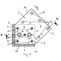
- the metal plate 1 is screwed with a quadrangular cross-section table leg 2.
- the metal plate 1 is pentagonal. It has the through holes 20 and is divided into the two areas 3 and 4.
- the first area 3 is screwed to the table leg 2, while the second area 4 is to be screwed to the table top 5.
- the first region 3 is inserted into the milled recess 6 on the end face of the table leg 2. It consists of a quadrilateral made by the edges 8 of the Table leg 2 and the edge 9 of the plate 1 is limited. The edges 9 abut against the inner edges of the milled recess 6, while the dashed lines 8 reproduce the inner contour of the table leg 2.
- the second region 4 of the metal plate 1 projects inwardly beyond the end face of the table leg 2. It is bounded by the three edges 18 of the metal plate 1 and the broken lines 8, which show the inner contour of the table leg 2. This area 4 is used to attach the table leg 2 to the table top 5. It has the through holes 20 which are equal in diameter d as the through holes 20 for the screws 12.
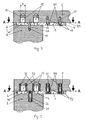
- a milled recess 6 is mounted, which receives the first region 3 of the metal plate 1.
- the depth of the milled recess 6 is equal to the thickness S of the metal plate 1.
- the milled recess 6 can be on the outer sides 22 of the Tischbeins2 the edge 7, so that when the table is fully assembled, the metal plate 1 is laterally hidden outside.
- the table top 5 and the table legs 2 are provided with blind holes 24 for the screws 12.
- the screws 12 preferably have the same length.
- the bolts 13 are equipped with the stubs 26, which are frictionally pressed into through holes 20.
- the diameter D of the bolts 13 above the through holes 20 is larger than the remaining inserted into the through hole 20 stub 26th
- the embodiment of the Fig. 3 corresponds in its components to the example of the Fig. 1 and 2 with the deviation that in the blind holes 16 and 24 screw sleeves 30 and 31 are screwed.
- the ringmuffen 31 have external thread with a reverse rotation and internal thread for metric screws 32.
- the larger ringmuffen 30 are screwed, the cavities 33, however, are without thread.
- the design after Fig. 3 is the preferred embodiment of the invention. It results in a particularly high strength of the connection of a table top with the associated table legs on a metal plate to be screwed thereto.
Landscapes
- Engineering & Computer Science (AREA)
- General Engineering & Computer Science (AREA)
- Mechanical Engineering (AREA)
- Furniture Connections (AREA)
Claims (16)
- Assemblage d'une plaque en bois (5) à un ou plusieurs supports en bois (2) par le biais d'un kit de montage constitué d'une plaque métallique (1) avec des orifices (20) et d'un nombre de vis (12) correspondant au nombre des orifices (20), caractérisé en ce que la plaque métallique (1) est divisée en deux régions (3 et 4) dont la première région (3) correspond dans sa dimension en surface approximativement à la face frontale du support en bois (2) et est introduite, puis vissée, dans un fraisage (6) dans l'épaisseur (S) de la plaque métallique (1) réalisé dans la face frontale du ou des supports en bois (2) et dont la deuxième région (4) faisant saillie au-delà de la face frontale du support en bois (2) est vissée au côté inférieur (23) de la plaque en bois (5).
- Assemblage selon la revendication 1, caractérisé en ce que les orifices (20) pour les régions (3, 4) présentent des biseaux (15) pour recevoir de manière renfoncée les têtes de vis.
- Assemblage selon la revendication 2, caractérisé en ce que les vis (12) pour les régions (3, 4) sont des vis à bois (12) avec des têtes fraisées.
- Assemblage selon l'une quelconque ou plusieurs des revendications 1 à 3, caractérisé en ce que la plaque en bois (5) et les supports en bois (2) sont pourvus de trous borgnes (24) pour recevoir les vis (12).
- Assemblage selon la revendication 4, caractérisé en ce que des manchons de vis (31) avec un filetage de vis intérieur sont vissés dans les trous borgnes (24).
- Assemblage selon la revendication 5, caractérisé en ce que les manchons de vis (31) présentent une protection contre le retrait.
- Assemblage selon les revendications 5 ou 6, caractérisé en ce que les vis (12) pour la deuxième région (4) présentent des têtes fraisées.
- Assemblage selon l'une quelconque ou plusieurs des revendications 1 à 7, caractérisé en ce que la plaque métallique (1) présente dans la première région (3) au moins un boulon de positionnement et de retenue (13) qui peut être introduit avec ajustement dans un trou borgne (16) dans la plaque en bois (5).
- Assemblage selon l'une quelconque ou plusieurs des revendications 1 à 8, caractérisé en ce que la plaque en bois (5) présente un nombre de trous borgnes (16) pour recevoir le ou les boulons de retenue (13) correspondant au nombre des boulons de retenue (13).
- Assemblage selon la revendication 9, caractérisé en ce que des manchons de vis (30) sont vissés dans les trous borgnes (16) pour les boulons de retenue (13), les boulons de retenue (13) pouvant être insérés avec ajustement dans les cavités (33) des trous borgnes.
- Assemblage selon l'une quelconque ou plusieurs des revendications 8 à 10, caractérisé en ce que la fixation des boulons (13) à la plaque métallique (1) s'effectue par le biais d'orifices (20) dans la plaque métallique (1), le diamètre des boulons (13) correspondant au diamètre intérieur des orifices (20) pour les vis (12) et les boulons (13) étant introduits avec ajustement par friction dans les orifices (20).
- Assemblage selon l'une quelconque ou plusieurs des revendications 8 à 11, caractérisé en ce que le boulon (13) présente, au dessus de l'orifice (20), un diamètre élargi (D).
- Assemblage selon l'une quelconque des revendications 1 à 12, caractérisé en ce que le ou les supports en bois (2) sont disposés au niveau des arêtes latérales de la plaque en bois (5).
- Assemblage selon l'une quelconque des revendications 1 à 12, caractérisé en ce que les supports en bois (2) sont disposés au niveau des coins de la plaque en bois (5).
- Assemblage selon l'une quelconque ou plusieurs des revendications 1 à 14, caractérisé en ce que la bordure en bois du fraisage (6) présente un passage pour la deuxième région (4) de la plaque métallique (1).
- Assemblage selon l'une quelconques ou plusieurs des revendications 1 à 15, caractérisé en ce que les bordures en bois au niveau des fraisages (6) des supports en bois (2) sont orientées vers le côté extérieur de la plaque en bois (5).
Applications Claiming Priority (1)
| Application Number | Priority Date | Filing Date | Title |
|---|---|---|---|
| DE201110016520 DE102011016520A1 (de) | 2011-04-08 | 2011-04-08 | Verbindung einer Holzplatte mit einem oder mehreren Holzständern und Gegenstand hergestellt unter Verwendung der Verbindung |
Publications (2)
| Publication Number | Publication Date |
|---|---|
| EP2508099A1 EP2508099A1 (fr) | 2012-10-10 |
| EP2508099B1 true EP2508099B1 (fr) | 2015-10-21 |
Family
ID=45976622
Family Applications (1)
| Application Number | Title | Priority Date | Filing Date |
|---|---|---|---|
| EP12002429.4A Active EP2508099B1 (fr) | 2011-04-08 | 2012-04-04 | Liaison d'une plaque en bois et d'un ou plusieurs supports en bois et objet fabriqué en utilisant cette liaison |
Country Status (3)
| Country | Link |
|---|---|
| EP (1) | EP2508099B1 (fr) |
| DE (1) | DE102011016520A1 (fr) |
| DK (1) | DK2508099T3 (fr) |
Families Citing this family (1)
| Publication number | Priority date | Publication date | Assignee | Title |
|---|---|---|---|---|
| DE102013018121A1 (de) | 2013-11-29 | 2015-06-03 | David Shemmer | Tisch, Sitzbank oder dgl. aus einer Holzplatte und seitlichen Abstützungen |
Family Cites Families (3)
| Publication number | Priority date | Publication date | Assignee | Title |
|---|---|---|---|---|
| CA2070350A1 (fr) * | 1992-06-03 | 1993-12-04 | John Geiger | Element de fixation pour patte |
| JP4338957B2 (ja) * | 2002-11-08 | 2009-10-07 | 株式会社岡村製作所 | テーブル等の支柱取付け構造 |
| JP2010094396A (ja) * | 2008-10-20 | 2010-04-30 | Itoki Corp | テーブルの脚取付構造 |
-
2011
- 2011-04-08 DE DE201110016520 patent/DE102011016520A1/de not_active Withdrawn
-
2012
- 2012-04-04 EP EP12002429.4A patent/EP2508099B1/fr active Active
- 2012-04-04 DK DK12002429.4T patent/DK2508099T3/en active
Also Published As
| Publication number | Publication date |
|---|---|
| DE102011016520A1 (de) | 2012-10-11 |
| DK2508099T3 (en) | 2016-01-18 |
| EP2508099A1 (fr) | 2012-10-10 |
Similar Documents
| Publication | Publication Date | Title |
|---|---|---|
| DE69516003T2 (de) | Konstruktionssystem mit vorgefertigten lochanordnungen | |
| WO1994009280A1 (fr) | Element de construction metallique pour l'assemblage de pieces en bois, en derives du bois ou en matiere plastique | |
| DE2525791A1 (de) | Moebelsystem auf der basis von gestellen und profilen | |
| EP3115521B1 (fr) | Armature et systeme d'armature destine a la liaison reversible d'elements plats et systeme de paroi verticale modulaire | |
| DE2126955A1 (de) | Beschlag zum Zusammenfügen von zwei und mehr aufeinander senkrecht stehenden Wänden, insbesondere von plattenförmigen Möbelwänden | |
| EP2508099B1 (fr) | Liaison d'une plaque en bois et d'un ou plusieurs supports en bois et objet fabriqué en utilisant cette liaison | |
| DE102004002394A1 (de) | Set zum Zusammensetzen von Möbeln, entsprechendes Möbel und Verfahren zum Aufbau eines Möbels bzw. zum Bereitstellen eines Sets | |
| DE102017130758B4 (de) | Untergestell für Möbel | |
| EP0038086A2 (fr) | Elément de construction pour la production de tréteaux, meubles, étagères, bâtiments transportables et objet construit à partir de cet élément | |
| DE3320962C2 (de) | Eckverbindung | |
| DE202015100534U1 (de) | Eckmontage zum Festverbund mindestens zweier winklig zueinander angeordneter Bauteile | |
| DE9401222U1 (de) | Regal- und/oder Schranksystem | |
| DE202012010397U1 (de) | Verbindungsvorrichtung | |
| DE102022119058B3 (de) | System zum modularen Aufbau von Traggerüsten | |
| DE29603402U1 (de) | Rahmenwerk mit Winkel- oder Eckverbindungen von Metallprofilen, insbesondere aus Leichtmetall | |
| DE7910865U1 (de) | Regal | |
| EP3922804A1 (fr) | Partie de meuble | |
| DE202015101420U1 (de) | Eckmontagesatz | |
| DE29819228U1 (de) | Verbindungselement für Bauteile und Verbindungsanordnung | |
| EP4289310A1 (fr) | Élément de montage pour stocker des objets dans une cloison de construction sèche et agencement doté de celui-ci | |
| DE2410211A1 (de) | Kombinationsmoebel | |
| DE29719761U1 (de) | Vorrichtung zum lösbaren Verbinden von Wandelementen | |
| DE2331366C3 (de) | Aus Standardelementen zusammenschraubbares Metallgerüst für die Herstellung von Möbelstücken | |
| DE29713464U1 (de) | Glasmöbel aus verbundenen Flachglasplatten, insbesondere Glastische und Glasregale | |
| DE102012014686A1 (de) | Bauteilesystem zur Herstellung einer lösbaren Verbindung von Bauelementen |
Legal Events
| Date | Code | Title | Description |
|---|---|---|---|
| PUAI | Public reference made under article 153(3) epc to a published international application that has entered the european phase |
Free format text: ORIGINAL CODE: 0009012 |
|
| AK | Designated contracting states |
Kind code of ref document: A1 Designated state(s): AL AT BE BG CH CY CZ DE DK EE ES FI FR GB GR HR HU IE IS IT LI LT LU LV MC MK MT NL NO PL PT RO RS SE SI SK SM TR |
|
| AX | Request for extension of the european patent |
Extension state: BA ME |
|
| 17P | Request for examination filed |
Effective date: 20121217 |
|
| GRAP | Despatch of communication of intention to grant a patent |
Free format text: ORIGINAL CODE: EPIDOSNIGR1 |
|
| INTG | Intention to grant announced |
Effective date: 20150618 |
|
| GRAS | Grant fee paid |
Free format text: ORIGINAL CODE: EPIDOSNIGR3 |
|
| GRAA | (expected) grant |
Free format text: ORIGINAL CODE: 0009210 |
|
| AK | Designated contracting states |
Kind code of ref document: B1 Designated state(s): AL AT BE BG CH CY CZ DE DK EE ES FI FR GB GR HR HU IE IS IT LI LT LU LV MC MK MT NL NO PL PT RO RS SE SI SK SM TR |
|
| REG | Reference to a national code |
Ref country code: GB Ref legal event code: FG4D Free format text: NOT ENGLISH Ref country code: NL Ref legal event code: MP Effective date: 20151021 |
|
| REG | Reference to a national code |
Ref country code: CH Ref legal event code: EP |
|
| REG | Reference to a national code |
Ref country code: AT Ref legal event code: REF Ref document number: 755988 Country of ref document: AT Kind code of ref document: T Effective date: 20151115 |
|
| REG | Reference to a national code |
Ref country code: IE Ref legal event code: FG4D Free format text: LANGUAGE OF EP DOCUMENT: GERMAN |
|
| REG | Reference to a national code |
Ref country code: DE Ref legal event code: R096 Ref document number: 502012004988 Country of ref document: DE |
|
| REG | Reference to a national code |
Ref country code: DK Ref legal event code: T3 Effective date: 20160111 |
|
| REG | Reference to a national code |
Ref country code: SE Ref legal event code: TRGR |
|
| REG | Reference to a national code |
Ref country code: LT Ref legal event code: MG4D |
|
| PG25 | Lapsed in a contracting state [announced via postgrant information from national office to epo] |
Ref country code: ES Free format text: LAPSE BECAUSE OF FAILURE TO SUBMIT A TRANSLATION OF THE DESCRIPTION OR TO PAY THE FEE WITHIN THE PRESCRIBED TIME-LIMIT Effective date: 20151021 Ref country code: HR Free format text: LAPSE BECAUSE OF FAILURE TO SUBMIT A TRANSLATION OF THE DESCRIPTION OR TO PAY THE FEE WITHIN THE PRESCRIBED TIME-LIMIT Effective date: 20151021 Ref country code: IS Free format text: LAPSE BECAUSE OF FAILURE TO SUBMIT A TRANSLATION OF THE DESCRIPTION OR TO PAY THE FEE WITHIN THE PRESCRIBED TIME-LIMIT Effective date: 20160221 Ref country code: NO Free format text: LAPSE BECAUSE OF FAILURE TO SUBMIT A TRANSLATION OF THE DESCRIPTION OR TO PAY THE FEE WITHIN THE PRESCRIBED TIME-LIMIT Effective date: 20160121 Ref country code: NL Free format text: LAPSE BECAUSE OF FAILURE TO SUBMIT A TRANSLATION OF THE DESCRIPTION OR TO PAY THE FEE WITHIN THE PRESCRIBED TIME-LIMIT Effective date: 20151021 Ref country code: IT Free format text: LAPSE BECAUSE OF FAILURE TO SUBMIT A TRANSLATION OF THE DESCRIPTION OR TO PAY THE FEE WITHIN THE PRESCRIBED TIME-LIMIT Effective date: 20151021 Ref country code: LT Free format text: LAPSE BECAUSE OF FAILURE TO SUBMIT A TRANSLATION OF THE DESCRIPTION OR TO PAY THE FEE WITHIN THE PRESCRIBED TIME-LIMIT Effective date: 20151021 |
|
| PG25 | Lapsed in a contracting state [announced via postgrant information from national office to epo] |
Ref country code: FI Free format text: LAPSE BECAUSE OF FAILURE TO SUBMIT A TRANSLATION OF THE DESCRIPTION OR TO PAY THE FEE WITHIN THE PRESCRIBED TIME-LIMIT Effective date: 20151021 Ref country code: PL Free format text: LAPSE BECAUSE OF FAILURE TO SUBMIT A TRANSLATION OF THE DESCRIPTION OR TO PAY THE FEE WITHIN THE PRESCRIBED TIME-LIMIT Effective date: 20151021 Ref country code: GR Free format text: LAPSE BECAUSE OF FAILURE TO SUBMIT A TRANSLATION OF THE DESCRIPTION OR TO PAY THE FEE WITHIN THE PRESCRIBED TIME-LIMIT Effective date: 20160122 Ref country code: PT Free format text: LAPSE BECAUSE OF FAILURE TO SUBMIT A TRANSLATION OF THE DESCRIPTION OR TO PAY THE FEE WITHIN THE PRESCRIBED TIME-LIMIT Effective date: 20160222 Ref country code: RS Free format text: LAPSE BECAUSE OF FAILURE TO SUBMIT A TRANSLATION OF THE DESCRIPTION OR TO PAY THE FEE WITHIN THE PRESCRIBED TIME-LIMIT Effective date: 20151021 Ref country code: LV Free format text: LAPSE BECAUSE OF FAILURE TO SUBMIT A TRANSLATION OF THE DESCRIPTION OR TO PAY THE FEE WITHIN THE PRESCRIBED TIME-LIMIT Effective date: 20151021 |
|
| REG | Reference to a national code |
Ref country code: DE Ref legal event code: R097 Ref document number: 502012004988 Country of ref document: DE |
|
| PG25 | Lapsed in a contracting state [announced via postgrant information from national office to epo] |
Ref country code: CZ Free format text: LAPSE BECAUSE OF FAILURE TO SUBMIT A TRANSLATION OF THE DESCRIPTION OR TO PAY THE FEE WITHIN THE PRESCRIBED TIME-LIMIT Effective date: 20151021 |
|
| PLBE | No opposition filed within time limit |
Free format text: ORIGINAL CODE: 0009261 |
|
| STAA | Information on the status of an ep patent application or granted ep patent |
Free format text: STATUS: NO OPPOSITION FILED WITHIN TIME LIMIT |
|
| PG25 | Lapsed in a contracting state [announced via postgrant information from national office to epo] |
Ref country code: EE Free format text: LAPSE BECAUSE OF FAILURE TO SUBMIT A TRANSLATION OF THE DESCRIPTION OR TO PAY THE FEE WITHIN THE PRESCRIBED TIME-LIMIT Effective date: 20151021 Ref country code: BE Free format text: LAPSE BECAUSE OF NON-PAYMENT OF DUE FEES Effective date: 20160430 Ref country code: SM Free format text: LAPSE BECAUSE OF FAILURE TO SUBMIT A TRANSLATION OF THE DESCRIPTION OR TO PAY THE FEE WITHIN THE PRESCRIBED TIME-LIMIT Effective date: 20151021 Ref country code: RO Free format text: LAPSE BECAUSE OF FAILURE TO SUBMIT A TRANSLATION OF THE DESCRIPTION OR TO PAY THE FEE WITHIN THE PRESCRIBED TIME-LIMIT Effective date: 20151021 Ref country code: SK Free format text: LAPSE BECAUSE OF FAILURE TO SUBMIT A TRANSLATION OF THE DESCRIPTION OR TO PAY THE FEE WITHIN THE PRESCRIBED TIME-LIMIT Effective date: 20151021 |
|
| 26N | No opposition filed |
Effective date: 20160722 |
|
| PG25 | Lapsed in a contracting state [announced via postgrant information from national office to epo] |
Ref country code: SI Free format text: LAPSE BECAUSE OF FAILURE TO SUBMIT A TRANSLATION OF THE DESCRIPTION OR TO PAY THE FEE WITHIN THE PRESCRIBED TIME-LIMIT Effective date: 20151021 |
|
| PG25 | Lapsed in a contracting state [announced via postgrant information from national office to epo] |
Ref country code: LU Free format text: LAPSE BECAUSE OF FAILURE TO SUBMIT A TRANSLATION OF THE DESCRIPTION OR TO PAY THE FEE WITHIN THE PRESCRIBED TIME-LIMIT Effective date: 20160404 |
|
| REG | Reference to a national code |
Ref country code: IE Ref legal event code: MM4A |
|
| REG | Reference to a national code |
Ref country code: FR Ref legal event code: ST Effective date: 20161230 |
|
| PG25 | Lapsed in a contracting state [announced via postgrant information from national office to epo] |
Ref country code: FR Free format text: LAPSE BECAUSE OF NON-PAYMENT OF DUE FEES Effective date: 20160502 |
|
| PG25 | Lapsed in a contracting state [announced via postgrant information from national office to epo] |
Ref country code: IE Free format text: LAPSE BECAUSE OF NON-PAYMENT OF DUE FEES Effective date: 20160404 |
|
| PG25 | Lapsed in a contracting state [announced via postgrant information from national office to epo] |
Ref country code: CY Free format text: LAPSE BECAUSE OF FAILURE TO SUBMIT A TRANSLATION OF THE DESCRIPTION OR TO PAY THE FEE WITHIN THE PRESCRIBED TIME-LIMIT Effective date: 20151021 Ref country code: HU Free format text: LAPSE BECAUSE OF FAILURE TO SUBMIT A TRANSLATION OF THE DESCRIPTION OR TO PAY THE FEE WITHIN THE PRESCRIBED TIME-LIMIT; INVALID AB INITIO Effective date: 20120404 |
|
| PG25 | Lapsed in a contracting state [announced via postgrant information from national office to epo] |
Ref country code: MT Free format text: LAPSE BECAUSE OF FAILURE TO SUBMIT A TRANSLATION OF THE DESCRIPTION OR TO PAY THE FEE WITHIN THE PRESCRIBED TIME-LIMIT Effective date: 20151021 Ref country code: MC Free format text: LAPSE BECAUSE OF FAILURE TO SUBMIT A TRANSLATION OF THE DESCRIPTION OR TO PAY THE FEE WITHIN THE PRESCRIBED TIME-LIMIT Effective date: 20151021 Ref country code: MK Free format text: LAPSE BECAUSE OF FAILURE TO SUBMIT A TRANSLATION OF THE DESCRIPTION OR TO PAY THE FEE WITHIN THE PRESCRIBED TIME-LIMIT Effective date: 20151021 Ref country code: TR Free format text: LAPSE BECAUSE OF FAILURE TO SUBMIT A TRANSLATION OF THE DESCRIPTION OR TO PAY THE FEE WITHIN THE PRESCRIBED TIME-LIMIT Effective date: 20151021 |
|
| PG25 | Lapsed in a contracting state [announced via postgrant information from national office to epo] |
Ref country code: BG Free format text: LAPSE BECAUSE OF FAILURE TO SUBMIT A TRANSLATION OF THE DESCRIPTION OR TO PAY THE FEE WITHIN THE PRESCRIBED TIME-LIMIT Effective date: 20151021 |
|
| PG25 | Lapsed in a contracting state [announced via postgrant information from national office to epo] |
Ref country code: AL Free format text: LAPSE BECAUSE OF FAILURE TO SUBMIT A TRANSLATION OF THE DESCRIPTION OR TO PAY THE FEE WITHIN THE PRESCRIBED TIME-LIMIT Effective date: 20151021 |
|
| PGFP | Annual fee paid to national office [announced via postgrant information from national office to epo] |
Ref country code: IT Payment date: 20190624 Year of fee payment: 15 |
|
| PGFP | Annual fee paid to national office [announced via postgrant information from national office to epo] |
Ref country code: SE Payment date: 20190422 Year of fee payment: 8 |
|
| PGFP | Annual fee paid to national office [announced via postgrant information from national office to epo] |
Ref country code: GB Payment date: 20190423 Year of fee payment: 8 |
|
| REG | Reference to a national code |
Ref country code: DK Ref legal event code: EBP Effective date: 20200430 |
|
| PG25 | Lapsed in a contracting state [announced via postgrant information from national office to epo] |
Ref country code: SE Free format text: LAPSE BECAUSE OF NON-PAYMENT OF DUE FEES Effective date: 20200405 |
|
| GBPC | Gb: european patent ceased through non-payment of renewal fee |
Effective date: 20200404 |
|
| PG25 | Lapsed in a contracting state [announced via postgrant information from national office to epo] |
Ref country code: GB Free format text: LAPSE BECAUSE OF NON-PAYMENT OF DUE FEES Effective date: 20200404 Ref country code: DK Free format text: LAPSE BECAUSE OF NON-PAYMENT OF DUE FEES Effective date: 20200430 |
|
| PGFP | Annual fee paid to national office [announced via postgrant information from national office to epo] |
Ref country code: DE Payment date: 20250311 Year of fee payment: 14 |
|
| PGFP | Annual fee paid to national office [announced via postgrant information from national office to epo] |
Ref country code: CH Payment date: 20250501 Year of fee payment: 14 |
|
| PGFP | Annual fee paid to national office [announced via postgrant information from national office to epo] |
Ref country code: AT Payment date: 20250424 Year of fee payment: 14 |