EP2508721B1 - Kombi-Prozess-System mit integrierter Kohlevergasung und mit Dampfabsorptionskühler - Google Patents
Kombi-Prozess-System mit integrierter Kohlevergasung und mit Dampfabsorptionskühler Download PDFInfo
- Publication number
- EP2508721B1 EP2508721B1 EP12160288.2A EP12160288A EP2508721B1 EP 2508721 B1 EP2508721 B1 EP 2508721B1 EP 12160288 A EP12160288 A EP 12160288A EP 2508721 B1 EP2508721 B1 EP 2508721B1
- Authority
- EP
- European Patent Office
- Prior art keywords
- combined cycle
- gasification combined
- cycle system
- integrated gasification
- carbon dioxide
- Prior art date
- Legal status (The legal status is an assumption and is not a legal conclusion. Google has not performed a legal analysis and makes no representation as to the accuracy of the status listed.)
- Active
Links
Images


Classifications
-
- C—CHEMISTRY; METALLURGY
- C10—PETROLEUM, GAS OR COKE INDUSTRIES; TECHNICAL GASES CONTAINING CARBON MONOXIDE; FUELS; LUBRICANTS; PEAT
- C10J—PRODUCTION OF PRODUCER GAS, WATER-GAS, SYNTHESIS GAS FROM SOLID CARBONACEOUS MATERIAL, OR MIXTURES CONTAINING THESE GASES; CARBURETTING AIR OR OTHER GASES
- C10J3/00—Production of combustible gases containing carbon monoxide from solid carbonaceous fuels
- C10J3/46—Gasification of granular or pulverulent flues in suspension
- C10J3/466—Entrained flow processes
-
- F—MECHANICAL ENGINEERING; LIGHTING; HEATING; WEAPONS; BLASTING
- F01—MACHINES OR ENGINES IN GENERAL; ENGINE PLANTS IN GENERAL; STEAM ENGINES
- F01K—STEAM ENGINE PLANTS; STEAM ACCUMULATORS; ENGINE PLANTS NOT OTHERWISE PROVIDED FOR; ENGINES USING SPECIAL WORKING FLUIDS OR CYCLES
- F01K23/00—Plants characterised by more than one engine delivering power external to the plant, the engines being driven by different fluids
- F01K23/02—Plants characterised by more than one engine delivering power external to the plant, the engines being driven by different fluids the engine cycles being thermally coupled
- F01K23/06—Plants characterised by more than one engine delivering power external to the plant, the engines being driven by different fluids the engine cycles being thermally coupled combustion heat from one cycle heating the fluid in another cycle
- F01K23/067—Plants characterised by more than one engine delivering power external to the plant, the engines being driven by different fluids the engine cycles being thermally coupled combustion heat from one cycle heating the fluid in another cycle the combustion heat coming from a gasification or pyrolysis process, e.g. coal gasification
- F01K23/068—Plants characterised by more than one engine delivering power external to the plant, the engines being driven by different fluids the engine cycles being thermally coupled combustion heat from one cycle heating the fluid in another cycle the combustion heat coming from a gasification or pyrolysis process, e.g. coal gasification in combination with an oxygen producing plant, e.g. an air separation plant
-
- F—MECHANICAL ENGINEERING; LIGHTING; HEATING; WEAPONS; BLASTING
- F02—COMBUSTION ENGINES; HOT-GAS OR COMBUSTION-PRODUCT ENGINE PLANTS
- F02C—GAS-TURBINE PLANTS; AIR INTAKES FOR JET-PROPULSION PLANTS; CONTROLLING FUEL SUPPLY IN AIR-BREATHING JET-PROPULSION PLANTS
- F02C3/00—Gas-turbine plants characterised by the use of combustion products as the working fluid
- F02C3/20—Gas-turbine plants characterised by the use of combustion products as the working fluid using a special fuel, oxidant, or dilution fluid to generate the combustion products
- F02C3/26—Gas-turbine plants characterised by the use of combustion products as the working fluid using a special fuel, oxidant, or dilution fluid to generate the combustion products the fuel or oxidant being solid or pulverulent, e.g. in slurry or suspension
- F02C3/28—Gas-turbine plants characterised by the use of combustion products as the working fluid using a special fuel, oxidant, or dilution fluid to generate the combustion products the fuel or oxidant being solid or pulverulent, e.g. in slurry or suspension using a separate gas producer for gasifying the fuel before combustion
-
- F—MECHANICAL ENGINEERING; LIGHTING; HEATING; WEAPONS; BLASTING
- F25—REFRIGERATION OR COOLING; COMBINED HEATING AND REFRIGERATION SYSTEMS; HEAT PUMP SYSTEMS; MANUFACTURE OR STORAGE OF ICE; LIQUEFACTION SOLIDIFICATION OF GASES
- F25B—REFRIGERATION MACHINES, PLANTS OR SYSTEMS; COMBINED HEATING AND REFRIGERATION SYSTEMS; HEAT PUMP SYSTEMS
- F25B15/00—Sorption machines, plants or systems, operating continuously, e.g. absorption type
- F25B15/02—Sorption machines, plants or systems, operating continuously, e.g. absorption type without inert gas
-
- F—MECHANICAL ENGINEERING; LIGHTING; HEATING; WEAPONS; BLASTING
- F25—REFRIGERATION OR COOLING; COMBINED HEATING AND REFRIGERATION SYSTEMS; HEAT PUMP SYSTEMS; MANUFACTURE OR STORAGE OF ICE; LIQUEFACTION SOLIDIFICATION OF GASES
- F25B—REFRIGERATION MACHINES, PLANTS OR SYSTEMS; COMBINED HEATING AND REFRIGERATION SYSTEMS; HEAT PUMP SYSTEMS
- F25B27/00—Machines, plants or systems, using particular sources of energy
- F25B27/02—Machines, plants or systems, using particular sources of energy using waste heat, e.g. from internal-combustion engines
-
- C—CHEMISTRY; METALLURGY
- C10—PETROLEUM, GAS OR COKE INDUSTRIES; TECHNICAL GASES CONTAINING CARBON MONOXIDE; FUELS; LUBRICANTS; PEAT
- C10J—PRODUCTION OF PRODUCER GAS, WATER-GAS, SYNTHESIS GAS FROM SOLID CARBONACEOUS MATERIAL, OR MIXTURES CONTAINING THESE GASES; CARBURETTING AIR OR OTHER GASES
- C10J2300/00—Details of gasification processes
- C10J2300/16—Integration of gasification processes with another plant or parts within the plant
- C10J2300/164—Integration of gasification processes with another plant or parts within the plant with conversion of synthesis gas
- C10J2300/1643—Conversion of synthesis gas to energy
- C10J2300/1653—Conversion of synthesis gas to energy integrated in a gasification combined cycle [IGCC]
-
- C—CHEMISTRY; METALLURGY
- C10—PETROLEUM, GAS OR COKE INDUSTRIES; TECHNICAL GASES CONTAINING CARBON MONOXIDE; FUELS; LUBRICANTS; PEAT
- C10J—PRODUCTION OF PRODUCER GAS, WATER-GAS, SYNTHESIS GAS FROM SOLID CARBONACEOUS MATERIAL, OR MIXTURES CONTAINING THESE GASES; CARBURETTING AIR OR OTHER GASES
- C10J2300/00—Details of gasification processes
- C10J2300/16—Integration of gasification processes with another plant or parts within the plant
- C10J2300/1678—Integration of gasification processes with another plant or parts within the plant with air separation
-
- Y—GENERAL TAGGING OF NEW TECHNOLOGICAL DEVELOPMENTS; GENERAL TAGGING OF CROSS-SECTIONAL TECHNOLOGIES SPANNING OVER SEVERAL SECTIONS OF THE IPC; TECHNICAL SUBJECTS COVERED BY FORMER USPC CROSS-REFERENCE ART COLLECTIONS [XRACs] AND DIGESTS
- Y02—TECHNOLOGIES OR APPLICATIONS FOR MITIGATION OR ADAPTATION AGAINST CLIMATE CHANGE
- Y02A—TECHNOLOGIES FOR ADAPTATION TO CLIMATE CHANGE
- Y02A30/00—Adapting or protecting infrastructure or their operation
- Y02A30/27—Relating to heating, ventilation or air conditioning [HVAC] technologies
- Y02A30/274—Relating to heating, ventilation or air conditioning [HVAC] technologies using waste energy, e.g. from internal combustion engine
-
- Y—GENERAL TAGGING OF NEW TECHNOLOGICAL DEVELOPMENTS; GENERAL TAGGING OF CROSS-SECTIONAL TECHNOLOGIES SPANNING OVER SEVERAL SECTIONS OF THE IPC; TECHNICAL SUBJECTS COVERED BY FORMER USPC CROSS-REFERENCE ART COLLECTIONS [XRACs] AND DIGESTS
- Y02—TECHNOLOGIES OR APPLICATIONS FOR MITIGATION OR ADAPTATION AGAINST CLIMATE CHANGE
- Y02B—CLIMATE CHANGE MITIGATION TECHNOLOGIES RELATED TO BUILDINGS, e.g. HOUSING, HOUSE APPLIANCES OR RELATED END-USER APPLICATIONS
- Y02B30/00—Energy efficient heating, ventilation or air conditioning [HVAC]
- Y02B30/62—Absorption based systems
- Y02B30/625—Absorption based systems combined with heat or power generation [CHP], e.g. trigeneration
-
- Y—GENERAL TAGGING OF NEW TECHNOLOGICAL DEVELOPMENTS; GENERAL TAGGING OF CROSS-SECTIONAL TECHNOLOGIES SPANNING OVER SEVERAL SECTIONS OF THE IPC; TECHNICAL SUBJECTS COVERED BY FORMER USPC CROSS-REFERENCE ART COLLECTIONS [XRACs] AND DIGESTS
- Y02—TECHNOLOGIES OR APPLICATIONS FOR MITIGATION OR ADAPTATION AGAINST CLIMATE CHANGE
- Y02E—REDUCTION OF GREENHOUSE GAS [GHG] EMISSIONS, RELATED TO ENERGY GENERATION, TRANSMISSION OR DISTRIBUTION
- Y02E20/00—Combustion technologies with mitigation potential
- Y02E20/16—Combined cycle power plant [CCPP], or combined cycle gas turbine [CCGT]
-
- Y—GENERAL TAGGING OF NEW TECHNOLOGICAL DEVELOPMENTS; GENERAL TAGGING OF CROSS-SECTIONAL TECHNOLOGIES SPANNING OVER SEVERAL SECTIONS OF THE IPC; TECHNICAL SUBJECTS COVERED BY FORMER USPC CROSS-REFERENCE ART COLLECTIONS [XRACs] AND DIGESTS
- Y02—TECHNOLOGIES OR APPLICATIONS FOR MITIGATION OR ADAPTATION AGAINST CLIMATE CHANGE
- Y02E—REDUCTION OF GREENHOUSE GAS [GHG] EMISSIONS, RELATED TO ENERGY GENERATION, TRANSMISSION OR DISTRIBUTION
- Y02E20/00—Combustion technologies with mitigation potential
- Y02E20/16—Combined cycle power plant [CCPP], or combined cycle gas turbine [CCGT]
- Y02E20/18—Integrated gasification combined cycle [IGCC], e.g. combined with carbon capture and storage [CCS]
-
- Y—GENERAL TAGGING OF NEW TECHNOLOGICAL DEVELOPMENTS; GENERAL TAGGING OF CROSS-SECTIONAL TECHNOLOGIES SPANNING OVER SEVERAL SECTIONS OF THE IPC; TECHNICAL SUBJECTS COVERED BY FORMER USPC CROSS-REFERENCE ART COLLECTIONS [XRACs] AND DIGESTS
- Y02—TECHNOLOGIES OR APPLICATIONS FOR MITIGATION OR ADAPTATION AGAINST CLIMATE CHANGE
- Y02E—REDUCTION OF GREENHOUSE GAS [GHG] EMISSIONS, RELATED TO ENERGY GENERATION, TRANSMISSION OR DISTRIBUTION
- Y02E20/00—Combustion technologies with mitigation potential
- Y02E20/32—Direct CO2 mitigation
-
- Y—GENERAL TAGGING OF NEW TECHNOLOGICAL DEVELOPMENTS; GENERAL TAGGING OF CROSS-SECTIONAL TECHNOLOGIES SPANNING OVER SEVERAL SECTIONS OF THE IPC; TECHNICAL SUBJECTS COVERED BY FORMER USPC CROSS-REFERENCE ART COLLECTIONS [XRACs] AND DIGESTS
- Y02—TECHNOLOGIES OR APPLICATIONS FOR MITIGATION OR ADAPTATION AGAINST CLIMATE CHANGE
- Y02P—CLIMATE CHANGE MITIGATION TECHNOLOGIES IN THE PRODUCTION OR PROCESSING OF GOODS
- Y02P20/00—Technologies relating to chemical industry
- Y02P20/10—Process efficiency
-
- Y—GENERAL TAGGING OF NEW TECHNOLOGICAL DEVELOPMENTS; GENERAL TAGGING OF CROSS-SECTIONAL TECHNOLOGIES SPANNING OVER SEVERAL SECTIONS OF THE IPC; TECHNICAL SUBJECTS COVERED BY FORMER USPC CROSS-REFERENCE ART COLLECTIONS [XRACs] AND DIGESTS
- Y02—TECHNOLOGIES OR APPLICATIONS FOR MITIGATION OR ADAPTATION AGAINST CLIMATE CHANGE
- Y02P—CLIMATE CHANGE MITIGATION TECHNOLOGIES IN THE PRODUCTION OR PROCESSING OF GOODS
- Y02P20/00—Technologies relating to chemical industry
- Y02P20/10—Process efficiency
- Y02P20/129—Energy recovery, e.g. by cogeneration, H2recovery or pressure recovery turbines
-
- Y—GENERAL TAGGING OF NEW TECHNOLOGICAL DEVELOPMENTS; GENERAL TAGGING OF CROSS-SECTIONAL TECHNOLOGIES SPANNING OVER SEVERAL SECTIONS OF THE IPC; TECHNICAL SUBJECTS COVERED BY FORMER USPC CROSS-REFERENCE ART COLLECTIONS [XRACs] AND DIGESTS
- Y02—TECHNOLOGIES OR APPLICATIONS FOR MITIGATION OR ADAPTATION AGAINST CLIMATE CHANGE
- Y02P—CLIMATE CHANGE MITIGATION TECHNOLOGIES IN THE PRODUCTION OR PROCESSING OF GOODS
- Y02P80/00—Climate change mitigation technologies for sector-wide applications
- Y02P80/10—Efficient use of energy, e.g. using compressed air or pressurized fluid as energy carrier
- Y02P80/15—On-site combined power, heat or cool generation or distribution, e.g. combined heat and power [CHP] supply
Definitions
- the present application relates generally to integrated gasification combined cycle systems and more particularly relates to an integrated gasification combined cycle system using vapor absorption chilling driven by the waste heat of a gas compression system.
- carbon dioxide (“CO 2 ”) produced in power generation facilities is considered to be a greenhouse gas.
- the carbon dioxide produced in the overall power production process generally is sequestered and then recycled for other purposes or otherwise disposed.
- IGCC integrated gasification combined cycle
- the pre-combustion capture of carbon dioxide is preferred. Once captured, the carbon dioxide generally may be compressed before transport, disposal, or other use.
- various integrated gasification combined cycle system designs require the compression of the carbon dioxide before the gas is recycled to, for example, the feed system, the gasifier, or other locations in the overall system.
- the net power output from an integrated gasification combined cycle system or other type of power plant is determined by the output of the gas turbine engine(s) operating on a syngas or other fuel. Any parasitical electrical or other type of load in the power plant serves to reduce the net generation output.
- the compression of carbon dioxide generally requires large amounts of auxiliary compression power. This compression power usually is provided by electric drives or steam turbines. This type of parasitic load thus results in lower overall power plant net output and efficiency.
- the use of cooling tower water to cool the carbon dioxide compressors may be expensive and impractical in areas where water may be expensive and/or rare.
- Such improved integrated gasification combined cycle systems may limit the parasitic load caused by compressing and cooling of carbon dioxide so as to increase net power generation output and efficiency while maintaining the ecological benefits of carbon dioxide sequestration.
- US-A-2009/158701 concerns systems and methods for power generation with carbon dioxide isolation.
- the power generation system includes a partial oxidation unit that provide a high pressure fuel stream to a carbon dioxide separation system.
- the Ryan Holmes process is used, which produces high purity carbon dioxide rich streams at a pressure of about 30 bar, leading to reduced compression costs.
- EP-A-2 251 626 concerns a system and method for reduction of diluent gaseous nitrogen (DGAN) compressor power in a combined cycle power plant.
- the technique uses a vapor absorption chiller that generates and transmits cooled fluid to one or more heat exchangers located upstream and/or downstream of a compressor of the DGAN compressor system.
- the present invention provides an integrated gasification combined cycle system as defined in appended claim 1 and a method of cooling a power plant component as defined in appended claim 14.
- the present disclosure provides an integrated gasification combined cycle system.
- the integrated gasification combined cycle system may include a gas turbine engine, one or more power plant components, one or more carbon dioxide compressors, and a vapor absorption chiller.
- the vapor absorption chiller is driven by a waste heat source flow from the carbon dioxide compressors to produce a chilling medium flow to cool the power plant components.
- the present disclosure further provides a method of cooling a power plant component.
- the method may include the steps of generating a waste heat source flow in one or more carbon dioxide compressors, driving a vapor absorption chiller with the waste heat source flow, generating a chilling medium flow in the vapor absorption chiller, and cooling the power plant component with the chilling medium flow.
- the method further may include the steps of vaporizing a refrigerant in a generator of the vapor absorption chiller, liquefying the refrigerant in a condenser, expanding the refrigerant in an evaporator, reabsorbing the refrigerant in an absorber, and repeating the cycle.
- the present disclosure further may provide an integrated gasification combined cycle system.
- the integrated gasification combined cycle system may include one or more carbon dioxide compressors, one or more compressor coolers, and a vapor absorption chiller.
- the vapor absorption chiller is driven by a waste heat source flow from the carbon dioxide compressors to produce a chilling medium flow to cool the compressor coolers.
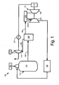
- FIG. 1 shows a schematic view of a known integrated gasification combined cycle system 100. Only those elements related to the subject matter described herein are shown for purposes of simplification.
- the overall integrated gasification combined cycle system 100 may have many other configurations and may use many other types of equipment.
- the integrated gasification combined cycle system 100 may include one or more gas turbine engines 110.
- the gas turbine engine 110 may include a compressor 120 to compress an incoming flow of air.
- the compressor 120 delivers the compressed flow of air to a combustor 130.
- the combustor 130 mixes the compressed flow of air with a compressed flow of fuel and ignites the mixture.
- the gas turbine engine 110 may include any number of combustors 130.
- the hot combustion gases are in turn delivered to a turbine 140.
- the hot combustion gases drive the turbine 140 so as to produce mechanical work.
- the mechanical work produced in the turbine 140 drives the compressor 120 and an external load 150 such as an electrical generator and the like.
- the gas turbine engine 110 may have many other configurations and may use many other types of equipment.
- the integrated gasification combined cycle system 100 may have multiple gas turbine engines 110.
- the gas turbine engine 110 may use natural gas, various types of syngas, combinations thereof, and other types of fuels.
- the syngas may be derived from a syngas production system 115.
- the syngas production system 115 may produce the syngas from a source of coal 160 according to several known techniques.
- the coal may be delivered to a gasifier 170.
- the gasifier 170 mixes the coal from the coal source 160 with oxygen from an air separation unit 180 or other source to produce a syngas 190 via a partial oxidation process or otherwise.
- the air separation unit 180 may receive extraction air from the compressor 120 or other source.
- Other types of gasification techniques and other sources of syngas may be used herein.
- the raw syngas 190 from the gasifier 170 then may be sent to an acid gas removal system 200.
- the acid gas removal system 200 removes a flow of carbon dioxide 205, hydrogen sulfide (H 2 S), and other gases from the syngas 190.
- the acid gases may be removed via a catalytic process, a solvent, and other known techniques.
- the now clean syngas 195 then may be forwarded to the combustor 130 of the gas turbine engine 110 for combustion in the manner described above or otherwise.
- the syngas production system 115 also may include one or more carbon dioxide compressor 210 to compress the flow of carbon dioxide 205 produced by the acid gas removal system 200 or otherwise. As described above, the flow of carbon dioxide 205 generally is required to be compressed before being sequestered, recycled, or otherwise disposed.
- the carbon dioxide compressors 210 may be of conventional design.
- the carbon dioxide compressors 210 may be driven in this example by an electrical motor 220, a steam turbine, or other types of drive devices.
- the electrical motor 220 or other type of drive device may be of conventional design.
- the electrical motor 220 may be considered a parasitic load on the overall integrated gasification combined cycle system 100 in that the motor 220 reduces the gross power generation therein.
- the carbon dioxide compressors 210 may be water cooled and in communication with a cooling tower 230 or other source of a cooling medium. Other configurations and other components may be used herein.
- a number of other steps may be used between the gasifier 170 and the acid gas removal system 200 and in the overall integrated gasification combined cycle system 100.
- particulate scrubbing, cooling, hydrolysis, water gas shifting, mercury removal, and other steps may be used herein.
- clean syngas heating and moisture addition may take place between the acid gas removal system 200 and the gas turbine engine 110 or otherwise.
- Many other steps, devices, and processes may be used herein.
- Fig. 2 shows an example of a vapor absorption chiller 240 as may be used herein.
- the vapor absorption chiller 240 creates refrigeration by absorbing and releasing a refrigerant 245 from an absorbent 250 in a refrigerant solution 255.
- the refrigerant 245 in the refrigerant solution 255 may be vaporized in a generator 260 in communication with a waste heat source flow 270.
- the vapor refrigerant 245 then may be liquefied in a condenser 280 and flow to an evaporator 290.
- the refrigerant 245 may expand in the evaporator 290 and cool below atmospheric temperature.
- the now cool refrigerant 245 may exchange heat with a chilling medium flow 300 in the evaporator 290.
- the refrigerant 245 again may vaporize in the evaporator 290 and pass to an absorber 310.
- the refrigerant vapor 245 then may be reabsorbed into the absorbent 250 in the absorber 310.
- the now refrigerant rich refrigerant solution 255 may be returned to the generator 260 via a pump 320 or other type of mechanical fluid device so as to repeat the cycle.
- Other configurations and other components may be used herein.
- Fig. 3 shows a portion of an integrated gasification combined cycle system 330 as may be used herein.
- the integrated gasification combined cycle system 330 may include the gas turbine engine 110, the carbon dioxide compressor 210, and similar types of devices.
- the gas turbine engine 110 may have a power plant component 335 positioned thereabout.
- the power plant component 335 may be a turbine inlet chiller 340.
- the turbine inlet chiller 340 may be any type of heat exchange device so as to chill an incoming flow of air 360 into the components of the gas turbine engine 110.
- the turbine inlet chiller 340 may be of conventional design.
- the power plant component 335 may be any device in the overall integrated gasification combined cycle system 330 that requires a cooling flow.
- the integrated gasification combined cycle system 330 also may use a vapor absorption chiller 370.
- the vapor absorption chiller 370 may be similar to that described above.
- the vapor absorption chiller 370 may be in communication with and cools the carbon dioxide compressor 210 via a compressor heat exchanger 380.
- the vapor absorption chiller 370 may be in communication with the compressor heat exchanger 380 in a first fluid circuit 390 while the carbon dioxide compressor 210 and the compressor heat exchanger 380 may be in communication via a second fluid circuit 400.
- Other components and other configurations may be used herein.
- Waste heat generated in the carbon dioxide compressor 210 may be absorbed in the second fluid circuit 400.
- the second fluid circuit 400 then may be cooled in the compressor heat exchanger 380 with the first fluid circuit 390.
- the heat absorbed by the first fluid circuit 390 acts as the waste heat source flow 270 in communication with the generator 260 of the vapor absorption chiller 370.
- the now cooled first fluid circuit 390 then may return to the compressor heat exchanger 380 and repeat the cooling cycle.
- the carbon dioxide compressor 210 may be cooled in a closed loop system not requiring the use of a cooling tower.
- the waste heat produced by the carbon dioxide compressor 210 feeds the generator 260 of the vapor absorption chiller 370 in a closed loop system with the compressor heat exchanger 380.
- the chilling medium flow 300 cooled by the evaporator 290 of the vapor absorption chiller 370 may be directed to the turbine inlet air chiller 340 to chill the incoming flow of air 360. Chilling the incoming flow of air 360 should improve overall gas turbine engine output, particularly on warmer days.
- the operation of the turbine inlet air chiller 340 thus is provided by the waste heat source flow 270 of the carbon dioxide compressor 210 that would otherwise not provide useful work.
- waste heat source flow 270 may provide an overall reduction in parasitic power loses.
- the chilling medium flow 300 produced by the vapor absorption chiller 370 also may be used with any power plant component 335 for any purpose.
- any power plant component 335 for example, inlet and inter-stage cooling, lube oil cooling, syngas cooling, air separation unit cooling, on-base cooling, condenser cooling water cooling, and many other purposes.
- the cooling provided herein is "free" in that it does not increase the overall parasitic power loses.
- Fig. 4 shows a further example of an integrated gasification combined cycle system 410 as may be described herein.
- the integrated gasification combined cycle system 410 also includes a number of the carbon dioxide compressors 210.
- a low pressure compressor 420, an intermediate pressure compressor 430, and a high pressure compressor 440 may be used. Any number of carbon dioxide compressors 210 may be used herein.
- the carbon dioxide compressors 210 may compress a portion 445 the flow of carbon dioxide 205 to a supercritical state so as to liquefy the flow for transport and the like.
- the integrated gasification combined cycle system 410 also includes a vapor absorption chiller 450.
- the vapor absorption chiller 450 may be similar to that described above.
- the integrated combined cycle system 410 uses the chilling medium flow 300 produced by the evaporator 290 to cool the carbon dioxide compressors 210 via a number of compressor coolers 460.
- a pre-cooler 470, a number of inter-coolers 480, and an after-cooler 490 may be used herein. Any number of compressor coolers 460 may be used herein.
- the flow of carbon dioxide 205 is used as both the waste heat source flow 270 and the refrigerant 245 in the generator 260.
- the absorbent 250 may be an alcohol, an ether, and the like.
- the flow of carbon dioxide 205 may be vaporized in the generator 260 and flow to the condenser 280 in a super-critical state.
- the carbon dioxide 205 then may be liquefied in the condenser 280 and flow to the evaporator 290.
- the flow of carbon dioxide 205 may be expanded therein so as to provide cooling.
- the flow of carbon dioxide 205 exchanges heat with the chilling medium flow 300.
- the chilling medium flow 300 may be returned to the compressor coolers 460 for cooling therein.
- the flow of carbon dioxide 205 then may be returned to the absorber 310 for further cycling.
- the flow of carbon dioxide 205 at high temperature may be directly injected into the absorbent 250.
- the same amount of the liquid carbon dioxide 205 may be taken out from the cycle before the evaporator 290 as was added to the cycle in the generator 260.
- the recovered carbon dioxide 205 may be put back into the compression process via a pump 500 or other type of fluid device.
- the integrated combined cycle system 410 thus uses the waste heat produced by the carbon dioxide compressors 210 and the flow of carbon dioxide 205 itself to drive the vapor absorption chiller 450.
- the vapor absorption chiller 450 produces the chilling medium flow 300 to cool the carbon dioxide compressors 210 via the compressor coolers 460.
- the compressor coolers 460 thus may be considered the power plant component 335 herein.
- the chilling medium flow 300 used herein is more efficient than those produced by typical cooling towers and the like. As such, the cooler temperature of the chilling medium flow 300 dictates less pressure to liquefy the supercritical carbon dioxide flow 445 and, hence, overall less compression work. Less compression work thus results in less overall parasitic energy drain due to the carbon dioxide compressors 210.
- the chilling medium flow 300 produced by the vapor absorption chiller 450 may be used for many other purposes in the overall integrated gasification combined cycle system 410 described herein.
- the chilling effect produced herein should improve overall system performance in that the chilling effect is provided without overall system parasitic power loses.
- the systems described herein may be optimized for maximum recover of waste heat to enable further performance augmentation.
- integrated gasification combined cycle systems are described herein, the vapor absorption techniques described herein may be applicable to any type of power plant requiring compression of carbon dioxide and the like.
Landscapes
- Engineering & Computer Science (AREA)
- Chemical & Material Sciences (AREA)
- Combustion & Propulsion (AREA)
- Mechanical Engineering (AREA)
- General Engineering & Computer Science (AREA)
- Physics & Mathematics (AREA)
- Thermal Sciences (AREA)
- Oil, Petroleum & Natural Gas (AREA)
- Organic Chemistry (AREA)
- Engine Equipment That Uses Special Cycles (AREA)
- Separation By Low-Temperature Treatments (AREA)
Claims (15)
- Gas- und Dampfkraftwerkssystem mit integrierter Kohlevergasung (330), das Folgendes umfasst:eine oder mehrere Kraftwerkskomponenten (335);einen oder mehrere Kohlendioxidkompressoren (210); undeinen Dampfabsorptionskühler (240);wobei der Dampfabsorptionskühler (240) durch einen Abwärmequellenstrom (270) aus dem einem oder den mehreren Kohlendioxidkompressoren (210) angetrieben werden kann, um einen Kühlmediumstrom (300) zur Kühlung der einer oder mehreren Kraftwerkskomponenten (335) herzustellen.
- Gas- und Dampfkraftwerkssystem mit integrierter Kohlevergasung nach Anspruch 1, wobei die eine oder mehreren Kraftwerkskomponente/n (335) einen oder mehrere Turbineneinlasskühler (340) umfasst/umfassen.
- Gas- und Dampfkraftwerkssystem mit integrierter Kohlevergasung nach Anspruch 1 oder Anspruch 2, wobei die eine oder mehreren Kraftwerkskomponente/n (335) einen oder mehrere Turbineneinlasskühler (460) umfasst/umfassen.
- Gas- und Dampfkraftwerkssystem mit integrierter Kohlevergasung nach Anspruch 3, wobei der eine oder die mehreren Kompressorkühler (460) einen Vorkühler (470), einen Zwischenkühler (480) und einen Nachkühler (490) umfasst/umfassen.
- Gas- und Dampfkraftwerkssystem mit integrierter Kohlevergasung nach einem der Ansprüche 1 bis 4, das weiterhin einen Kompressor-Wärmetauscher (380) in Verbindung mit dem einen oder den mehreren Kohlendioxidkompressor/en (210) und dem Dampfabsorptionskühler (240) umfasst.
- Gas- und Dampfkraftwerkssystem mit integrierter Kohlevergasung nach Anspruch 5, wobei der Kompressor-Wärmetauscher (380) und der Dampfabsorptionskühler (240) über einen ersten Fluidkreislauf (390) miteinander verbunden sind.
- Gas- und Dampfkraftwerkssystem mit integrierter Kohlevergasung nach Anspruch 5 oder Anspruch 6, wobei der Kompressor-Wärmetauscher (380) und der eine oder die mehreren Kohlendioxidkompressor/en (210) über einen zweiten Flüssigkeitskreislauf (400) verbunden ist/sind.
- Gas- und Dampfkraftwerkssystem mit integrierter Kohlevergasung nach einem der vorstehenden Ansprüche, wobei der Abwärmequellenstrom (270) einen Kohlendioxidstrom (205) umfasst.
- Gas- und Dampfkraftwerkssystem mit integrierter Kohlevergasung nach einem der vorstehenden Ansprüche, wobei der eine oder die mehreren Kohlendioxidkompressor/en (210) einen Niederdruckkompressor (420), einen Mitteldruckkompressor (430) und einen Hochdruckkompressor (440) umfasst/umfassen.
- Gas- und Dampfkraftwerkssystem mit integrierter Kohlevergasung nach einem der vorstehenden Ansprüche, wobei der Abwärmequellenstrom (240) ein darin enthaltenes Kältemittel (245) umfasst.
- Gas- und Dampfkraftwerkssystem mit integrierter Kohlevergasung nach Anspruch 10, wobei das Kältemittel (245) einen Kohlendioxidstrom (205) umfasst.
- Gas- und Dampfkraftwerkssystem mit integrierter Kohlevergasung nach einem der vorstehenden Ansprüche, wobei der Dampfabsorptionskühler (240) ein darin enthaltenes Absorptionsmittel (250) umfasst.
- Gas- und Dampfkraftwerkssystem mit integrierter Kohlevergasung nach Anspruch 12, wobei das Absorptionsmittel (250) einen Alkohol oder Ether umfasst.
- Verfahren zur Kühlung einer Kraftwerkskomponente (335), das Folgendes umfasst:Generieren eines Abwärmequellenstroms (270) in einem oder mehreren Kohlendioxidkompressoren (210);Antreiben eines Dampfabsorptionskühlers (240) mit dem Abwärmequellenstrom (270);Generieren eines Kühlmediumstroms (300) in dem Dampfabsorptionskühler (240); undKühlen der Kraftwerkskomponente (335) mit dem Kühlmediumstrom (300).
- Verfahren nach Anspruch 14, das weiterhin die folgenden Schritte umfasst:Verdampfen eines Kühlmittels (245) in einem Generator (260) des Dampfabsorptionskühlers (240);Verflüssigen des Kühlmittels (245) in einem Kondensator (280);Expandieren des Kühlmittels (245) in einem Verdampfer (290); undResorbieren des Kühlmittels (245) in einem Absorber (310).
Priority Applications (1)
| Application Number | Priority Date | Filing Date | Title |
|---|---|---|---|
| PL12160288T PL2508721T3 (pl) | 2011-03-23 | 2012-03-20 | Układ gazowo-parowy ze zintegrowanym zgazowaniem z chłodzeniem absorpcyjnym |
Applications Claiming Priority (1)
| Application Number | Priority Date | Filing Date | Title |
|---|---|---|---|
| US13/069,456 US8631660B2 (en) | 2011-03-23 | 2011-03-23 | Integrated gasification combined cycle system with vapor absorption chilling |
Publications (3)
| Publication Number | Publication Date |
|---|---|
| EP2508721A2 EP2508721A2 (de) | 2012-10-10 |
| EP2508721A3 EP2508721A3 (de) | 2014-03-12 |
| EP2508721B1 true EP2508721B1 (de) | 2015-05-27 |
Family
ID=45894248
Family Applications (1)
| Application Number | Title | Priority Date | Filing Date |
|---|---|---|---|
| EP12160288.2A Active EP2508721B1 (de) | 2011-03-23 | 2012-03-20 | Kombi-Prozess-System mit integrierter Kohlevergasung und mit Dampfabsorptionskühler |
Country Status (6)
| Country | Link |
|---|---|
| US (1) | US8631660B2 (de) |
| EP (1) | EP2508721B1 (de) |
| CN (1) | CN102691577B (de) |
| AU (1) | AU2012201567B2 (de) |
| ES (1) | ES2544612T3 (de) |
| PL (1) | PL2508721T3 (de) |
Families Citing this family (5)
| Publication number | Priority date | Publication date | Assignee | Title |
|---|---|---|---|---|
| US20110126563A1 (en) * | 2009-11-30 | 2011-06-02 | General Electric Company | Absorption chiller and system incorporating the same |
| WO2014168785A1 (en) | 2013-04-11 | 2014-10-16 | Carrier Corporation | Combined vapor absorption and mechanical compression cycle design |
| US10830105B2 (en) | 2016-12-12 | 2020-11-10 | General Electric Company | System and method for improving output and heat rate for a liquid natural gas combined cycle power plant |
| IL254616B (en) | 2017-09-24 | 2020-01-30 | N A M Tech Ltd | Combined-type cascade refrigerating apparatus |
| CN113738514B (zh) * | 2021-08-12 | 2022-07-12 | 南京航空航天大学 | 利用n2o预冷/助燃的多模态组合动力循环系统及方法 |
Family Cites Families (20)
| Publication number | Priority date | Publication date | Assignee | Title |
|---|---|---|---|---|
| JPS5268129A (en) * | 1975-12-05 | 1977-06-06 | Mitsui Toatsu Chem Inc | Recovery of unreacted material and heat on urea synthesis |
| US4936109A (en) | 1986-10-06 | 1990-06-26 | Columbia Energy Storage, Inc. | System and method for reducing gas compressor energy requirements |
| US5025631A (en) * | 1990-07-16 | 1991-06-25 | Garbo Paul W | Cogeneration system with low NOx combustion of fuel gas |
| US5203161A (en) * | 1990-10-30 | 1993-04-20 | Lehto John M | Method and arrangement for cooling air to gas turbine inlet |
| US5992512A (en) * | 1996-03-21 | 1999-11-30 | The Furukawa Electric Co., Ltd. | Heat exchanger tube and method for manufacturing the same |
| CA2257848A1 (en) * | 1996-06-21 | 1997-12-24 | Syntroleum Corporation | Synthesis gas production system and method |
| US6073454A (en) | 1998-07-10 | 2000-06-13 | Spauschus Associates, Inc. | Reduced pressure carbon dioxide-based refrigeration system |
| US6170263B1 (en) | 1999-05-13 | 2001-01-09 | General Electric Co. | Method and apparatus for converting low grade heat to cooling load in an integrated gasification system |
| US6550272B2 (en) * | 2000-11-08 | 2003-04-22 | Kawasaki Thermal Engineering Co., Ltd. | Absorption chiller/absorption chiller-heater having safety device |
| US6374630B1 (en) | 2001-05-09 | 2002-04-23 | The United States Of America As Represented By The Administrator Of The National Aeronautics And Space Administration | Carbon dioxide absorption heat pump |
| US6739119B2 (en) * | 2001-12-31 | 2004-05-25 | Donald C. Erickson | Combustion engine improvement |
| DE10214183C1 (de) | 2002-03-28 | 2003-05-08 | Siemens Ag | Kraftwerk zur Kälteerzeugung |
| KR100473566B1 (ko) * | 2002-10-10 | 2005-03-08 | 엘지전선 주식회사 | 연소영역 슬림형 흡수식 고온재생기 |
| US6745574B1 (en) * | 2002-11-27 | 2004-06-08 | Elliott Energy Systems, Inc. | Microturbine direct fired absorption chiller |
| JP4274846B2 (ja) * | 2003-04-30 | 2009-06-10 | 三菱重工業株式会社 | 二酸化炭素の回収方法及びそのシステム |
| WO2006046976A2 (en) * | 2004-06-14 | 2006-05-04 | University Of Florida Research Foundation, Inc. | Turbine system with exhaust gas recirculation and absorption refrigeration system |
| US7961835B2 (en) * | 2005-08-26 | 2011-06-14 | Keller Michael F | Hybrid integrated energy production process |
| US20090158701A1 (en) * | 2007-12-20 | 2009-06-25 | General Electric Company | Systems and methods for power generation with carbon dioxide isolation |
| CN101270689B (zh) * | 2008-04-30 | 2010-06-02 | 杭州杭氧透平机械有限公司 | 煤气化增压联合循环发电系统的能量转化和回收方法 |
| US20100275648A1 (en) * | 2009-05-04 | 2010-11-04 | General Elctric Company | Efficiently compressing nitrogen in a combined cycle power plant |
-
2011
- 2011-03-23 US US13/069,456 patent/US8631660B2/en active Active
-
2012
- 2012-03-16 AU AU2012201567A patent/AU2012201567B2/en active Active
- 2012-03-20 PL PL12160288T patent/PL2508721T3/pl unknown
- 2012-03-20 EP EP12160288.2A patent/EP2508721B1/de active Active
- 2012-03-20 ES ES12160288.2T patent/ES2544612T3/es active Active
- 2012-03-23 CN CN201210093441.1A patent/CN102691577B/zh active Active
Also Published As
| Publication number | Publication date |
|---|---|
| US20120240603A1 (en) | 2012-09-27 |
| ES2544612T3 (es) | 2015-09-02 |
| EP2508721A3 (de) | 2014-03-12 |
| US8631660B2 (en) | 2014-01-21 |
| AU2012201567A1 (en) | 2012-10-11 |
| CN102691577A (zh) | 2012-09-26 |
| PL2508721T3 (pl) | 2015-10-30 |
| EP2508721A2 (de) | 2012-10-10 |
| AU2012201567B2 (en) | 2016-05-26 |
| CN102691577B (zh) | 2015-11-25 |
Similar Documents
| Publication | Publication Date | Title |
|---|---|---|
| EP3310455B1 (de) | Integriertes verfahren zur co2-abscheidung aus verbrennungsmotoren mobiler quellen und verwendung in einem wärmekraftproduktionszyklus | |
| CA2801492C (en) | Stoichiometric combustion with exhaust gas recirculation and direct contact cooler | |
| US8438874B2 (en) | Natural gas liquefaction plant and motive power supply equipment for same | |
| RU2594096C2 (ru) | Устройство для компрессии диоксида углерода | |
| US20130312386A1 (en) | Combined cycle power plant with co2 capture plant | |
| CA2828766A1 (en) | Low emission turbine systems incorporating inlet compressor oxidant control apparatus and methods related thereto | |
| CA2828365A1 (en) | Systems and methods for carbon dioxide capture in low emission turbine systems | |
| US20210363900A1 (en) | System for recovering waste heat and method thereof | |
| EP2508721B1 (de) | Kombi-Prozess-System mit integrierter Kohlevergasung und mit Dampfabsorptionskühler | |
| WO2020247886A1 (en) | Cold recycle process for gas turbine inlet air cooling | |
| JP2003269114A (ja) | 電力・冷熱供給コンバインドシステムおよびその運転方法 | |
| JP2004150685A (ja) | 窒素製造設備及びタービン発電設備 | |
| CN102853633B (zh) | 空气分离装置以及包括该空气分离装置的系统 | |
| JP2003227314A (ja) | 排熱回収方法および排熱回収システム | |
| Carpenter | Process Reduces Carbon Emissions From Natural Gas Compression and Production | |
| RU2019119914A (ru) | Способ и установка для образования синтез-газа | |
| CN121539361A (zh) | 一种无需外部能量输入的碳捕集能源系统 | |
| Stankovic | Gas-Turbine-Cycle District Heating/Cooling-Power System With Refrigerating Exhaust |
Legal Events
| Date | Code | Title | Description |
|---|---|---|---|
| PUAI | Public reference made under article 153(3) epc to a published international application that has entered the european phase |
Free format text: ORIGINAL CODE: 0009012 |
|
| AK | Designated contracting states |
Kind code of ref document: A2 Designated state(s): AL AT BE BG CH CY CZ DE DK EE ES FI FR GB GR HR HU IE IS IT LI LT LU LV MC MK MT NL NO PL PT RO RS SE SI SK SM TR |
|
| AX | Request for extension of the european patent |
Extension state: BA ME |
|
| PUAL | Search report despatched |
Free format text: ORIGINAL CODE: 0009013 |
|
| AK | Designated contracting states |
Kind code of ref document: A3 Designated state(s): AL AT BE BG CH CY CZ DE DK EE ES FI FR GB GR HR HU IE IS IT LI LT LU LV MC MK MT NL NO PL PT RO RS SE SI SK SM TR |
|
| AX | Request for extension of the european patent |
Extension state: BA ME |
|
| RIC1 | Information provided on ipc code assigned before grant |
Ipc: F02C 3/28 20060101ALI20140131BHEP Ipc: C10J 3/00 20060101ALI20140131BHEP Ipc: F25B 15/00 20060101ALI20140131BHEP Ipc: F02C 7/143 20060101ALI20140131BHEP Ipc: F01K 23/06 20060101AFI20140131BHEP |
|
| 17P | Request for examination filed |
Effective date: 20140912 |
|
| RBV | Designated contracting states (corrected) |
Designated state(s): AL AT BE BG CH CY CZ DE DK EE ES FI FR GB GR HR HU IE IS IT LI LT LU LV MC MK MT NL NO PL PT RO RS SE SI SK SM TR |
|
| RIC1 | Information provided on ipc code assigned before grant |
Ipc: C10J 3/46 20060101ALI20141204BHEP Ipc: F25B 27/02 20060101ALI20141204BHEP Ipc: F02C 3/28 20060101ALI20141204BHEP Ipc: F02C 7/143 20060101ALI20141204BHEP Ipc: C10J 3/00 20060101ALI20141204BHEP Ipc: F01K 23/06 20060101AFI20141204BHEP Ipc: F25B 15/02 20060101ALI20141204BHEP Ipc: F25B 15/00 20060101ALI20141204BHEP |
|
| GRAP | Despatch of communication of intention to grant a patent |
Free format text: ORIGINAL CODE: EPIDOSNIGR1 |
|
| INTG | Intention to grant announced |
Effective date: 20150123 |
|
| GRAP | Despatch of communication of intention to grant a patent |
Free format text: ORIGINAL CODE: EPIDOSNIGR1 |
|
| GRAS | Grant fee paid |
Free format text: ORIGINAL CODE: EPIDOSNIGR3 |
|
| INTG | Intention to grant announced |
Effective date: 20150402 |
|
| GRAA | (expected) grant |
Free format text: ORIGINAL CODE: 0009210 |
|
| AK | Designated contracting states |
Kind code of ref document: B1 Designated state(s): AL AT BE BG CH CY CZ DE DK EE ES FI FR GB GR HR HU IE IS IT LI LT LU LV MC MK MT NL NO PL PT RO RS SE SI SK SM TR |
|
| REG | Reference to a national code |
Ref country code: GB Ref legal event code: FG4D |
|
| REG | Reference to a national code |
Ref country code: CH Ref legal event code: EP |
|
| REG | Reference to a national code |
Ref country code: AT Ref legal event code: REF Ref document number: 728984 Country of ref document: AT Kind code of ref document: T Effective date: 20150615 |
|
| REG | Reference to a national code |
Ref country code: IE Ref legal event code: FG4D |
|
| REG | Reference to a national code |
Ref country code: DE Ref legal event code: R096 Ref document number: 602012007507 Country of ref document: DE |
|
| REG | Reference to a national code |
Ref country code: NL Ref legal event code: T3 |
|
| REG | Reference to a national code |
Ref country code: ES Ref legal event code: FG2A Ref document number: 2544612 Country of ref document: ES Kind code of ref document: T3 Effective date: 20150902 |
|
| REG | Reference to a national code |
Ref country code: AT Ref legal event code: MK05 Ref document number: 728984 Country of ref document: AT Kind code of ref document: T Effective date: 20150527 |
|
| REG | Reference to a national code |
Ref country code: LT Ref legal event code: MG4D |
|
| PG25 | Lapsed in a contracting state [announced via postgrant information from national office to epo] |
Ref country code: NO Free format text: LAPSE BECAUSE OF FAILURE TO SUBMIT A TRANSLATION OF THE DESCRIPTION OR TO PAY THE FEE WITHIN THE PRESCRIBED TIME-LIMIT Effective date: 20150827 Ref country code: FI Free format text: LAPSE BECAUSE OF FAILURE TO SUBMIT A TRANSLATION OF THE DESCRIPTION OR TO PAY THE FEE WITHIN THE PRESCRIBED TIME-LIMIT Effective date: 20150527 Ref country code: LT Free format text: LAPSE BECAUSE OF FAILURE TO SUBMIT A TRANSLATION OF THE DESCRIPTION OR TO PAY THE FEE WITHIN THE PRESCRIBED TIME-LIMIT Effective date: 20150527 Ref country code: HR Free format text: LAPSE BECAUSE OF FAILURE TO SUBMIT A TRANSLATION OF THE DESCRIPTION OR TO PAY THE FEE WITHIN THE PRESCRIBED TIME-LIMIT Effective date: 20150527 Ref country code: PT Free format text: LAPSE BECAUSE OF FAILURE TO SUBMIT A TRANSLATION OF THE DESCRIPTION OR TO PAY THE FEE WITHIN THE PRESCRIBED TIME-LIMIT Effective date: 20150928 |
|
| REG | Reference to a national code |
Ref country code: PL Ref legal event code: T3 |
|
| PG25 | Lapsed in a contracting state [announced via postgrant information from national office to epo] |
Ref country code: AT Free format text: LAPSE BECAUSE OF FAILURE TO SUBMIT A TRANSLATION OF THE DESCRIPTION OR TO PAY THE FEE WITHIN THE PRESCRIBED TIME-LIMIT Effective date: 20150527 Ref country code: GR Free format text: LAPSE BECAUSE OF FAILURE TO SUBMIT A TRANSLATION OF THE DESCRIPTION OR TO PAY THE FEE WITHIN THE PRESCRIBED TIME-LIMIT Effective date: 20150828 Ref country code: RS Free format text: LAPSE BECAUSE OF FAILURE TO SUBMIT A TRANSLATION OF THE DESCRIPTION OR TO PAY THE FEE WITHIN THE PRESCRIBED TIME-LIMIT Effective date: 20150527 Ref country code: LV Free format text: LAPSE BECAUSE OF FAILURE TO SUBMIT A TRANSLATION OF THE DESCRIPTION OR TO PAY THE FEE WITHIN THE PRESCRIBED TIME-LIMIT Effective date: 20150527 Ref country code: BG Free format text: LAPSE BECAUSE OF FAILURE TO SUBMIT A TRANSLATION OF THE DESCRIPTION OR TO PAY THE FEE WITHIN THE PRESCRIBED TIME-LIMIT Effective date: 20150827 Ref country code: IS Free format text: LAPSE BECAUSE OF FAILURE TO SUBMIT A TRANSLATION OF THE DESCRIPTION OR TO PAY THE FEE WITHIN THE PRESCRIBED TIME-LIMIT Effective date: 20150927 |
|
| PG25 | Lapsed in a contracting state [announced via postgrant information from national office to epo] |
Ref country code: DK Free format text: LAPSE BECAUSE OF FAILURE TO SUBMIT A TRANSLATION OF THE DESCRIPTION OR TO PAY THE FEE WITHIN THE PRESCRIBED TIME-LIMIT Effective date: 20150527 Ref country code: EE Free format text: LAPSE BECAUSE OF FAILURE TO SUBMIT A TRANSLATION OF THE DESCRIPTION OR TO PAY THE FEE WITHIN THE PRESCRIBED TIME-LIMIT Effective date: 20150527 |
|
| PG25 | Lapsed in a contracting state [announced via postgrant information from national office to epo] |
Ref country code: CZ Free format text: LAPSE BECAUSE OF FAILURE TO SUBMIT A TRANSLATION OF THE DESCRIPTION OR TO PAY THE FEE WITHIN THE PRESCRIBED TIME-LIMIT Effective date: 20150527 Ref country code: SK Free format text: LAPSE BECAUSE OF FAILURE TO SUBMIT A TRANSLATION OF THE DESCRIPTION OR TO PAY THE FEE WITHIN THE PRESCRIBED TIME-LIMIT Effective date: 20150527 Ref country code: RO Free format text: LAPSE BECAUSE OF NON-PAYMENT OF DUE FEES Effective date: 20150527 |
|
| REG | Reference to a national code |
Ref country code: DE Ref legal event code: R097 Ref document number: 602012007507 Country of ref document: DE |
|
| PLBE | No opposition filed within time limit |
Free format text: ORIGINAL CODE: 0009261 |
|
| STAA | Information on the status of an ep patent application or granted ep patent |
Free format text: STATUS: NO OPPOSITION FILED WITHIN TIME LIMIT |
|
| PGFP | Annual fee paid to national office [announced via postgrant information from national office to epo] |
Ref country code: ES Payment date: 20160328 Year of fee payment: 5 |
|
| 26N | No opposition filed |
Effective date: 20160301 |
|
| PG25 | Lapsed in a contracting state [announced via postgrant information from national office to epo] |
Ref country code: SI Free format text: LAPSE BECAUSE OF FAILURE TO SUBMIT A TRANSLATION OF THE DESCRIPTION OR TO PAY THE FEE WITHIN THE PRESCRIBED TIME-LIMIT Effective date: 20150527 |
|
| PG25 | Lapsed in a contracting state [announced via postgrant information from national office to epo] |
Ref country code: BE Free format text: LAPSE BECAUSE OF FAILURE TO SUBMIT A TRANSLATION OF THE DESCRIPTION OR TO PAY THE FEE WITHIN THE PRESCRIBED TIME-LIMIT Effective date: 20150527 |
|
| PG25 | Lapsed in a contracting state [announced via postgrant information from national office to epo] |
Ref country code: MC Free format text: LAPSE BECAUSE OF FAILURE TO SUBMIT A TRANSLATION OF THE DESCRIPTION OR TO PAY THE FEE WITHIN THE PRESCRIBED TIME-LIMIT Effective date: 20150527 Ref country code: LU Free format text: LAPSE BECAUSE OF FAILURE TO SUBMIT A TRANSLATION OF THE DESCRIPTION OR TO PAY THE FEE WITHIN THE PRESCRIBED TIME-LIMIT Effective date: 20160320 |
|
| REG | Reference to a national code |
Ref country code: CH Ref legal event code: PL |
|
| GBPC | Gb: european patent ceased through non-payment of renewal fee |
Effective date: 20160320 |
|
| REG | Reference to a national code |
Ref country code: IE Ref legal event code: MM4A |
|
| REG | Reference to a national code |
Ref country code: FR Ref legal event code: ST Effective date: 20161130 |
|
| PG25 | Lapsed in a contracting state [announced via postgrant information from national office to epo] |
Ref country code: LI Free format text: LAPSE BECAUSE OF NON-PAYMENT OF DUE FEES Effective date: 20160331 Ref country code: FR Free format text: LAPSE BECAUSE OF NON-PAYMENT OF DUE FEES Effective date: 20160331 Ref country code: GB Free format text: LAPSE BECAUSE OF NON-PAYMENT OF DUE FEES Effective date: 20160320 Ref country code: CH Free format text: LAPSE BECAUSE OF NON-PAYMENT OF DUE FEES Effective date: 20160331 Ref country code: IE Free format text: LAPSE BECAUSE OF NON-PAYMENT OF DUE FEES Effective date: 20160320 |
|
| PG25 | Lapsed in a contracting state [announced via postgrant information from national office to epo] |
Ref country code: SE Free format text: LAPSE BECAUSE OF FAILURE TO SUBMIT A TRANSLATION OF THE DESCRIPTION OR TO PAY THE FEE WITHIN THE PRESCRIBED TIME-LIMIT Effective date: 20150527 |
|
| PG25 | Lapsed in a contracting state [announced via postgrant information from national office to epo] |
Ref country code: MT Free format text: LAPSE BECAUSE OF FAILURE TO SUBMIT A TRANSLATION OF THE DESCRIPTION OR TO PAY THE FEE WITHIN THE PRESCRIBED TIME-LIMIT Effective date: 20150527 |
|
| PG25 | Lapsed in a contracting state [announced via postgrant information from national office to epo] |
Ref country code: HU Free format text: LAPSE BECAUSE OF FAILURE TO SUBMIT A TRANSLATION OF THE DESCRIPTION OR TO PAY THE FEE WITHIN THE PRESCRIBED TIME-LIMIT; INVALID AB INITIO Effective date: 20120320 Ref country code: SM Free format text: LAPSE BECAUSE OF FAILURE TO SUBMIT A TRANSLATION OF THE DESCRIPTION OR TO PAY THE FEE WITHIN THE PRESCRIBED TIME-LIMIT Effective date: 20150527 Ref country code: CY Free format text: LAPSE BECAUSE OF FAILURE TO SUBMIT A TRANSLATION OF THE DESCRIPTION OR TO PAY THE FEE WITHIN THE PRESCRIBED TIME-LIMIT Effective date: 20150527 |
|
| PG25 | Lapsed in a contracting state [announced via postgrant information from national office to epo] |
Ref country code: TR Free format text: LAPSE BECAUSE OF FAILURE TO SUBMIT A TRANSLATION OF THE DESCRIPTION OR TO PAY THE FEE WITHIN THE PRESCRIBED TIME-LIMIT Effective date: 20150527 Ref country code: MT Free format text: LAPSE BECAUSE OF FAILURE TO SUBMIT A TRANSLATION OF THE DESCRIPTION OR TO PAY THE FEE WITHIN THE PRESCRIBED TIME-LIMIT Effective date: 20160331 Ref country code: MK Free format text: LAPSE BECAUSE OF FAILURE TO SUBMIT A TRANSLATION OF THE DESCRIPTION OR TO PAY THE FEE WITHIN THE PRESCRIBED TIME-LIMIT Effective date: 20150527 |
|
| REG | Reference to a national code |
Ref country code: ES Ref legal event code: FD2A Effective date: 20180629 |
|
| PG25 | Lapsed in a contracting state [announced via postgrant information from national office to epo] |
Ref country code: ES Free format text: LAPSE BECAUSE OF NON-PAYMENT OF DUE FEES Effective date: 20170321 |
|
| PG25 | Lapsed in a contracting state [announced via postgrant information from national office to epo] |
Ref country code: AL Free format text: LAPSE BECAUSE OF FAILURE TO SUBMIT A TRANSLATION OF THE DESCRIPTION OR TO PAY THE FEE WITHIN THE PRESCRIBED TIME-LIMIT Effective date: 20150527 |
|
| REG | Reference to a national code |
Ref country code: DE Ref legal event code: R081 Ref document number: 602012007507 Country of ref document: DE Owner name: AIR PRODUCTS AND CHEMICALS, INC. (N.D.GES.D. S, US Free format text: FORMER OWNER: GENERAL ELECTRIC COMPANY, SCHENECTADY, N.Y., US Ref country code: DE Ref legal event code: R081 Ref document number: 602012007507 Country of ref document: DE Owner name: AIR PRODUCTS AND CHEMICALS, INC. (N.D.GES.D. S, US Free format text: FORMER OWNER: GENERAL ELECTRIC COMPANY, SCHENECTADY, NY, US |
|
| REG | Reference to a national code |
Ref country code: NL Ref legal event code: PD Owner name: AIR PRODUCTS AND CHEMICALS, INC.; US Free format text: DETAILS ASSIGNMENT: CHANGE OF OWNER(S), ASSIGNMENT; FORMER OWNER NAME: GENERAL ELECTRIC COMPANY Effective date: 20200225 |
|
| P01 | Opt-out of the competence of the unified patent court (upc) registered |
Effective date: 20230516 |
|
| PGFP | Annual fee paid to national office [announced via postgrant information from national office to epo] |
Ref country code: PL Payment date: 20251230 Year of fee payment: 15 |
|
| PGFP | Annual fee paid to national office [announced via postgrant information from national office to epo] |
Ref country code: NL Payment date: 20260106 Year of fee payment: 15 |
|
| PGFP | Annual fee paid to national office [announced via postgrant information from national office to epo] |
Ref country code: DE Payment date: 20260102 Year of fee payment: 15 |
|
| PGFP | Annual fee paid to national office [announced via postgrant information from national office to epo] |
Ref country code: IT Payment date: 20260220 Year of fee payment: 15 |