EP2508806A2 - Système de pompe à chaleur et procédé de commande de l'unité de pompe à chaleur - Google Patents
Système de pompe à chaleur et procédé de commande de l'unité de pompe à chaleur Download PDFInfo
- Publication number
- EP2508806A2 EP2508806A2 EP12001735A EP12001735A EP2508806A2 EP 2508806 A2 EP2508806 A2 EP 2508806A2 EP 12001735 A EP12001735 A EP 12001735A EP 12001735 A EP12001735 A EP 12001735A EP 2508806 A2 EP2508806 A2 EP 2508806A2
- Authority
- EP
- European Patent Office
- Prior art keywords
- temperature
- change rate
- heat pump
- inflow
- outflow
- Prior art date
- Legal status (The legal status is an assumption and is not a legal conclusion. Google has not performed a legal analysis and makes no representation as to the accuracy of the status listed.)
- Granted
Links
Images

Classifications
-
- F—MECHANICAL ENGINEERING; LIGHTING; HEATING; WEAPONS; BLASTING
- F24—HEATING; RANGES; VENTILATING
- F24D—DOMESTIC- OR SPACE-HEATING SYSTEMS, e.g. CENTRAL HEATING SYSTEMS; DOMESTIC HOT-WATER SUPPLY SYSTEMS; ELEMENTS OR COMPONENTS THEREFOR
- F24D19/00—Details
- F24D19/10—Arrangement or mounting of control or safety devices
- F24D19/1006—Arrangement or mounting of control or safety devices for water heating systems
- F24D19/1009—Arrangement or mounting of control or safety devices for water heating systems for central heating
- F24D19/1039—Arrangement or mounting of control or safety devices for water heating systems for central heating the system uses a heat pump
-
- F—MECHANICAL ENGINEERING; LIGHTING; HEATING; WEAPONS; BLASTING
- F24—HEATING; RANGES; VENTILATING
- F24D—DOMESTIC- OR SPACE-HEATING SYSTEMS, e.g. CENTRAL HEATING SYSTEMS; DOMESTIC HOT-WATER SUPPLY SYSTEMS; ELEMENTS OR COMPONENTS THEREFOR
- F24D3/00—Hot-water central heating systems
- F24D3/02—Hot-water central heating systems with forced circulation, e.g. by pumps
-
- F—MECHANICAL ENGINEERING; LIGHTING; HEATING; WEAPONS; BLASTING
- F24—HEATING; RANGES; VENTILATING
- F24D—DOMESTIC- OR SPACE-HEATING SYSTEMS, e.g. CENTRAL HEATING SYSTEMS; DOMESTIC HOT-WATER SUPPLY SYSTEMS; ELEMENTS OR COMPONENTS THEREFOR
- F24D3/00—Hot-water central heating systems
- F24D3/18—Hot-water central heating systems using heat pumps
-
- F—MECHANICAL ENGINEERING; LIGHTING; HEATING; WEAPONS; BLASTING
- F24—HEATING; RANGES; VENTILATING
- F24H—FLUID HEATERS, e.g. WATER OR AIR HEATERS, HAVING HEAT-GENERATING MEANS, e.g. HEAT PUMPS, IN GENERAL
- F24H15/00—Control of fluid heaters
- F24H15/30—Control of fluid heaters characterised by control outputs; characterised by the components to be controlled
- F24H15/355—Control of heat-generating means in heaters
- F24H15/37—Control of heat-generating means in heaters of electric heaters
-
- F—MECHANICAL ENGINEERING; LIGHTING; HEATING; WEAPONS; BLASTING
- F24—HEATING; RANGES; VENTILATING
- F24H—FLUID HEATERS, e.g. WATER OR AIR HEATERS, HAVING HEAT-GENERATING MEANS, e.g. HEAT PUMPS, IN GENERAL
- F24H15/00—Control of fluid heaters
- F24H15/30—Control of fluid heaters characterised by control outputs; characterised by the components to be controlled
- F24H15/375—Control of heat pumps
- F24H15/38—Control of compressors of heat pumps
-
- F—MECHANICAL ENGINEERING; LIGHTING; HEATING; WEAPONS; BLASTING
- F24—HEATING; RANGES; VENTILATING
- F24D—DOMESTIC- OR SPACE-HEATING SYSTEMS, e.g. CENTRAL HEATING SYSTEMS; DOMESTIC HOT-WATER SUPPLY SYSTEMS; ELEMENTS OR COMPONENTS THEREFOR
- F24D2200/00—Heat sources or energy sources
- F24D2200/08—Electric heater
-
- F—MECHANICAL ENGINEERING; LIGHTING; HEATING; WEAPONS; BLASTING
- F24—HEATING; RANGES; VENTILATING
- F24D—DOMESTIC- OR SPACE-HEATING SYSTEMS, e.g. CENTRAL HEATING SYSTEMS; DOMESTIC HOT-WATER SUPPLY SYSTEMS; ELEMENTS OR COMPONENTS THEREFOR
- F24D2200/00—Heat sources or energy sources
- F24D2200/12—Heat pump
- F24D2200/123—Compression type heat pumps
-
- Y—GENERAL TAGGING OF NEW TECHNOLOGICAL DEVELOPMENTS; GENERAL TAGGING OF CROSS-SECTIONAL TECHNOLOGIES SPANNING OVER SEVERAL SECTIONS OF THE IPC; TECHNICAL SUBJECTS COVERED BY FORMER USPC CROSS-REFERENCE ART COLLECTIONS [XRACs] AND DIGESTS
- Y02—TECHNOLOGIES OR APPLICATIONS FOR MITIGATION OR ADAPTATION AGAINST CLIMATE CHANGE
- Y02B—CLIMATE CHANGE MITIGATION TECHNOLOGIES RELATED TO BUILDINGS, e.g. HOUSING, HOUSE APPLIANCES OR RELATED END-USER APPLICATIONS
- Y02B30/00—Energy efficient heating, ventilation or air conditioning [HVAC]
- Y02B30/12—Hot water central heating systems using heat pumps
Definitions
- the present invention relates to a control technique for a compressor provided to a heat pump system and, more particularly, to a control technique for a compressor in a case where the load is comparatively low as in an interim period between seasons.
- a heat pump type room heating system is conventionally available which generates hot water using a heat pump unit and supplies the generated hot water to a panel heater or the like, thereby performing room heating operation.
- the target temperature is set in accordance with the load of the operation or the like, and the heat pump unit is controlled such that the temperature (inflow temperature) of the hot water supplied to the panel heater or the like becomes equal to the target temperature.
- a temperature between the minimum temperature and maximum temperature predetermined before shipping or the like is set as the target temperature.
- the heat pump type room heating system to proceed with energy conservation, it is significant to operate the heat pump unit continuously as long as possible within a range not impairing the indoor amenities, by utilizing the characteristics of inverter control of the heat pump unit. If the target temperature is low, however, even when the room heating system is operated while suppressing the capacity of the heat pump unit as low as possible, the inflow temperature will exceed the target temperature very soon. In this case, the room heating system repeatedly continues the operation of temporarily stopping the heat pump unit when the inflow temperature exceeds the target temperature and operating the heat pump unit again when the inflow temperature falls below the target temperature. In other words, the continuous operation of the heat pump unit cannot be achieved. This is not preferable in promoting energy conservation.
- Patent Literature 1 describes continuous operation of the heat pump unit by forcibly manipulating the inflow temperature and the return temperature using a room heating mixing valve and a variable flow-rate circulating pump.
- a heat pump system is provided with a heat pump unit having a compressor and supplies a fluid heated by the heat pump unit to a fluid-using device that uses the fluid.
- the heat pump system includes:
- the minimum value preset before shipping or the like is not utilized. Instead, the minimum value of the target temperature of the inflow temperature is appropriately fixed according to the environment where the heat pump system is installed, and control operation is performed such that an unnecessarily low target temperature will not be set. Hence, the heat pump unit can be operated continuously, promoting energy conservation.
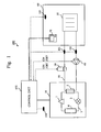
- Fig. 1 is a configuration diagram of a heat pump system 200 according to Embodiment 1.
- the heat pump system 200 includes a heat pump unit 10, an auxiliary heat source 20, a heat dissipator 30 (an example of a fluid-using device) installed in an indoor space 60, and a pump 40, which are connected sequentially via a fluid pipe 50.
- the fluid pipe 50 is connected to a heat exchanger 2 provided to the heat pump unit 10. Water (an example of the fluid) flows through the fluid pipe 50.
- a remote controller 70 to enter a preset temperature or the like is placed in the indoor space 60 where the heat dissipator 30 is installed.
- the heat pump unit 10 has a heat pump cycle formed by sequentially connecting a compressor 1, the heat exchanger 2, an expansion mechanism 3, and a heat exchanger 4 via a refrigerant pipe 5.
- a refrigerant circulates in the heat pump cycle in the order of the compressor 1, the heat exchanger 2, the expansion mechanism 3, and the heat exchanger 4, the refrigerant absorbs heat from air or the like with the heat exchanger 4, and dissipates heat with the heat exchanger 2 to the water flowing in the fluid pipe 50.
- the heat pump unit 10 heats the water flowing in the fluid pipe 50, thus making hot water.
- the auxiliary heat source 20 further heats the hot water heated by the heat pump unit 10.
- the auxiliary heat source 20 is an electric heater.
- the heat dissipator 30 dissipates the heat of the hot water heated by the heat pump unit 10 and auxiliary heat source 20 to the air in the indoor space 60. Consequently, the interior of the indoor space 60 becomes warm, and the hot water is cooled into cold water.
- the heat dissipator 30 is a floor heating panel or panel heater, or a fan coil unit.
- the floor heating panel or panel heater exchanges heat between the hot water and the air through heat exchange of natural convection achieved by heat radiation.
- the fan coil unit exchanges heat between the hot water and the air through heat exchange of forced convection achieved by an internal fan.
- the pump 40 circulates water in the fluid pipe 50.
- the heat pump system 200 also includes temperature sensors 101 to 104.
- the temperature sensor 101 inflow temperature measuring part
- the temperature sensor 102 (outflow temperature measuring part) measures the temperature of water flowing out from the heat dissipator 30, as an outflow temperature.
- the temperature sensor 103 (indoor temperature measurement part) measures the temperature of the air in the indoor space 60, as an indoor temperature.
- the temperature sensor 104 (outdoor air temperature measuring part) measures the temperature of outdoor air.
- the heat pump system 200 also includes a control unit 100 comprised of a microcomputer and the like.
- the control unit 100 acquires the temperatures measured by the temperature sensors 101 to 104, the preset temperature entered by the remote controller 70, the operation frequency of the heat pump unit 10 (compressor 1), and the like. Based on the acquired information, the control unit 100 sets the target temperature, and controls the heat pump unit 10 such that the temperature of the water to be supplied to the heat dissipator 30 becomes equal to the target temperature. Based on the acquired information, the control unit 100 also performs on/off control of the auxiliary heat source 20 and of the pump 40.
- Fig. 2 is a configuration diagram of the control unit 100 according to Embodiment 1.
- the control unit 100 includes a data acquisition part 110, a temperature setting part 120, a control part 130, a threshold storage part 140, and a threshold setting part 150.
- the data acquisition part 110 includes an inflow temperature acquisition part 111, an outflow temperature acquisition part 112, an indoor temperature acquisition part 113, an outdoor air temperature acquisition part 114, a preset temperature acquisition part 115, and a frequency acquisition part 116.
- the inflow temperature acquisition part 111 acquires the inflow temperature measured by the temperature sensor 101.
- the outflow temperature acquisition part 112 acquires the outflow temperature measured by the temperature sensor 102.
- the indoor temperature acquisition part 113 acquires the indoor temperature measured by the temperature sensor 103.
- the outdoor air temperature acquisition part 114 acquires the outdoor air temperature measured by the temperature sensor 104.
- the preset temperature acquisition part 115 acquires the preset temperature entered by the remote controller 70.
- the frequency acquisition part 116 acquires the operation frequency from the heat pump unit 10.
- the temperature setting part 120 includes a change rate calculation part 121, a convergence value calculation part 122, a minimum temperature setting part 123, and a target temperature setting part 124.
- the change rate calculation part 121 calculates the change rate of the inflow temperature per predetermined period of time (for example, 30 seconds in this case) at every preset time (for example, 15 seconds in this case) since the start of operation of the heat pump unit 10. Based on the outflow temperature acquired by the outflow temperature acquisition part 112, the change rate calculation part 121 also calculates the change rate of the outflow temperature per predetermined period of time (30 seconds) at every preset time (15 seconds) since the start of operation of the heat pump unit 10.
- the change of rate of the inflow temperature can be calculated from the inflow temperature measured at a certain time point and the inflow temperature measured at a time point preceding the certain time point by a predetermined period of time (30 seconds).
- the change rate of the outflow temperature can be calculated in the same manner as the change rate of the inflow temperature.
- the change rate of the inflow temperature will be called an inflow temperature change rate, and the change rate of the outflow temperature will be called an outflow temperature change rate.
- the convergence value calculation part 122 calculates the convergence value of the inflow temperature at every preset time (15 seconds) since the start of operation of the heat pump unit 10. Based on the outflow temperature acquired by the outflow temperature acquisition part 112, the convergence value calculation part 122 also calculates the convergence value of the outflow temperature at every preset time (15 seconds) since the start of operation of the heat pump unit 10.
- the convergence value of the inflow temperature can be calculated by calculating the curve of change of the inflow temperature from, for example, inflow temperatures measured at certain three time points.
- the convergence value of the outflow temperature can also be calculated in the same manner as the convergence value of the inflow temperature.
- the convergence value of the inflow temperature will be called an inflow temperature convergence value, and the convergence value of the outflow temperature will be called an outflow temperature convergence value.
- the minimum temperature setting part 123 sets the minimum temperature based on the inflow temperature change rate and outflow temperature change rate calculated by the change rate calculation part 121, the inflow temperature convergence value and outflow temperature convergence value calculated by the convergence value calculation part 122, the inflow temperature acquired by the inflow temperature acquisition part 111, and the outflow temperature acquired by the outflow temperature acquisition part 112.
- the minimum temperature setting part 123 sets, as the minimum temperature, the inflow temperature with which the difference between the inflow temperature change rate and the outflow temperature change rate is equal to or less than the change rate threshold stored in the threshold storage part 140 (to be described later); the difference between the inflow temperature convergence value and the outflow temperature convergence value is equal to or less than the convergence value threshold stored in the threshold storage part 140; and the difference between the inflow temperature and the outflow temperature is equal to or less than the temperature threshold stored in the threshold storage part 140.
- the target temperature setting part 124 Based on the indoor temperature acquired by the indoor temperature acquisition part 113, the outdoor air temperature acquired by the outdoor air temperature acquisition part 114, the preset temperature acquired by the preset temperature acquisition part 115, the operation frequency acquired by the frequency acquisition part 116, and the like, the target temperature setting part 124 sets a temperature equal to or higher than the minimum temperature set by the minimum temperature setting part 123, as the target temperature.
- the method with which the target temperature setting part 124 calculates the target temperature can be of any type although various methods have conventionally been employed. When the calculated target temperature is less than the minimum temperature, the target temperature setting part 124 sets the minimum temperature, as the target temperature.
- the control part 130 controls the heat pump unit 10 so the inflow temperature becomes equal to the target temperature set by the target temperature setting part 124. If a sufficient heating amount cannot be obtained with only the heat pump unit 10, the auxiliary heat source 20 is turned on so the inflow temperature becomes equal to the target temperature.
- the threshold storage part 140 is a storage device that stores the change rate threshold, the convergence value threshold, and the temperature threshold.
- the threshold setting part 150 stores the change rate threshold, the convergence value threshold, and the temperature threshold in the threshold storage part 140.
- the threshold setting part 150 stores the average value of the difference between the inflow temperature and outflow temperature measured when the load is high (the load is equal to or more than a predetermined value) as in winter, in the threshold storage part 140 as the convergence value threshold or temperature threshold.
- the threshold setting part 150 also stores the change rate threshold entered from the remote controller 70 or the like in the threshold storage part 140.
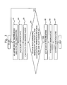
- Fig. 3 is a flowchart showing the flow of the control process of the control unit 100 according to Embodiment 1.
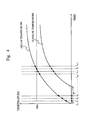
- Fig. 4 is a graph for explaining the control process of the control unit 100 according to Embodiment 1.
- the control unit 100 starts the control process shown in Fig. 3 .
- the heat pump unit 10 starts operation at a time point to.
- the axis of abscissa indicating the time is marked with t 1 , t 2 ,... at every preset time (15 seconds).
- the heat pump unit 10 is controlled by a predetermined frequency such as a rated frequency.
- the inflow temperature acquisition part 111 acquires the inflow temperature measured by the temperature sensor 101, at every preset time (15 seconds), and the outflow temperature acquisition part 112 acquires the outflow temperature measured by the temperature sensor 102, at every preset time (15 seconds).
- Fig. 4 shows that the inflow temperature and the outflow temperature are measured at every 15 seconds since the start of operation, for example, at to (0 second after the start of operation), at t 1 (15 seconds after the start of operation), at t 2 (30 seconds after the start of operation), and so on.
- the change rate calculation part 121 calculates the inflow temperature change rate at the current time point from the latest inflow temperature acquired in S1 and the inflow temperature of a time point preceding the current time point by a predetermined time (30 seconds).
- the change rate calculation part 121 also calculates the outflow temperature change rate at the current time point from the latest outflow temperature acquired in S1 and the outflow temperature of a time point preceding the current time point by a predetermined time (30 seconds).
- the inflow temperature change rate and the outflow temperature change rate are calculated at every 15 seconds since the time point t 2 which is 30 seconds after the operation is started. For example, at a time point t n of Fig.
- the inflow temperature change rate is calculated from the inflow temperature measured at the time point t n and the inflow temperature measured at the time point t n-2 .
- the outflow temperature change rate is calculated from the outflow temperature measured at the time point t n and the outflow temperature measured at the time point t n-2 .
- the convergence value calculation part 122 calculates the inflow temperature convergence value at the current time point from the latest inflow temperature acquired in S1, the inflow temperature of a time point preceding the current time point by a preset time (15 seconds), and the inflow temperature of a time point preceding the 15-second-preceding time point by a preset time (15 seconds) (that is, preceding the current time point by 30 seconds).
- the convergence value calculation part 122 also calculates the outflow temperature convergence value at the current time point from the latest outflow temperature acquired in S1, the outflow temperature of a time point preceding the current time point by a preset time (15 seconds), and the outflow temperature of a time point preceding the 15-second-preceding time point by a preset time (15 seconds).
- the inflow temperature convergence value and the outflow temperature convergence value are calculated at every 15 seconds since the time point t 2 which is 30 seconds after the operation is started.
- the inflow temperature convergence value is calculated from the inflow temperatures measured at the time points t n , t n-1 , and t n-2 .
- the outflow temperature convergence value is calculated from the outflow temperatures measured at the time points t n , t n-1 , and t n-2 .
- the minimum temperature setting part 123 checks whether or not the difference (change rate difference) between the inflow temperature change rate and the outflow temperature change rate is equal to or less than the change rate threshold, whether or not the difference (convergence value difference) between the inflow temperature convergence value and the outflow temperature convergence value is equal to or less than the convergence value threshold, and whether or not the difference (temperature difference) between the inflow temperature and the outflow temperature is equal to or less than the temperature threshold. If the respective differences are all equal to or less than the corresponding thresholds (YES in S4), the process of the minimum temperature setting part 123 advances to S5.
- the process of the minimum temperature setting part 123 returns to S1, and the change rate difference, convergence value difference, and temperature difference at a time point which is after the current time point by the preset time (15 seconds) are checked. For example, it is checked, of Fig. 4 , whether or not the change rate difference at the time point t n is equal to or less than the change rate threshold, whether or not the convergence value difference at the time point t n is equal to or less than the convergence value threshold, and whether or not the temperature difference at the time point t n is equal to or less than the temperature threshold.
- the process of the minimum temperature setting part 123 advances to S5. If any one difference is higher than the corresponding threshold (NO in S4), the process of the minimum temperature setting part 123 returns to S1, and the change rate difference, convergence value difference, and the temperature difference at the time point t n+1 are checked.
- the minimum temperature setting part 123 sets, as the minimum temperature, the inflow temperature measured at a time point where the respective values are all equal to or less than the corresponding thresholds. For example, if it is determined in S4 that the respective values at the time point t n of Fig. 4 are equal to or less than the corresponding thresholds, an inflow temperature Min measured at the time point t n is set as the minimum temperature.
- the target temperature setting part 124 calculates the target temperature in accordance with a predetermined method. If the target temperature obtained by calculation is less than the minimum temperature set in S5, the minimum temperature set in S5 is determined as the target temperature. Hence, a temperature equal to or higher than the minimum temperature is set as the target temperature.
- the control part 130 controls the heat pump unit 10 such that the inflow temperature becomes equal to the target temperature set in S6.
- the inflow temperature starts to rise immediately, but the outflow temperature starts to rise only after the lapse of a certain period of time (T in Fig. 4 ).
- the time difference T between the time point at which the inflow temperature starts to rise and the time point at which the outflow temperature starts to rise corresponds to the time taken since the water passes through the temperature sensor 101 until returning to the temperature sensor 102 via the heat dissipator 30.
- the heat dissipator 30 is arranged differently, and the number of units of the heat dissipators 30 and the like differs, so the total length of the fluid pipes 50 that connect the heat dissipators 30 differs.
- the time taken since the water passes through the temperature sensor 101 until returning to the temperature sensor 102 differs among the heat pump systems 200. Also, the change curves of the inflow temperature and outflow temperature differ depending on the capacity of the heat dissipator 30 to be installed, the room heating load, and the like.
- the minimum temperature is set by calculation using the inflow temperature and outflow temperature. Therefore, the minimum temperature can be set by considering the length of the fluid pipes 50, the capacity of the heat dissipator 30, the room heating load, and the like that differ among the heat pump systems 200. As a result, the heat pump unit 10 can be prevented from being repeatedly turned on/off due to an excessively low preset target temperature, so the continuous operation of the heat pump unit 10 can be realized. This promotes energy conservation.
- the temperature threshold and the convergence value threshold are determined based on the temperature difference between the inflow temperature and outflow temperature of a case where the room heating load is high as in winter. Therefore, an appropriate temperature threshold and an appropriate convergence value threshold can be set for each heat pump system 200. An appropriate minimum temperature can also be set accordingly.
- the minimum temperature setting part 123 may correct the minimum temperature based on the operation frequency acquired by the frequency acquisition part 116. Usually, the heat pump unit 10 operates more efficiently if it operates at a frequency close to the rated frequency. In view of this, the minimum temperature setting part 123 may correct the minimum temperature such that the operation frequency of the heat pump unit 10 becomes close to the rated frequency. Further, in S5 of Fig. 3 , the minimum temperature setting part 123 may correct the minimum temperature based on the outdoor air temperature acquired by the outdoor air temperature acquisition part 114. The curve indicating the relation between the operation efficiency and operation frequency of the heat pump unit 10 changes according to the outdoor air temperature.
- the minimum temperature setting part 123 may correct the minimum temperature considering the outdoor air temperature, such that the operation frequency of the heat pump unit 10 becomes close to the rated frequency.
- the minimum temperature setting part 123 may correct the minimum temperature based on the indoor temperature acquired by the indoor temperature acquisition part 113 or the preset temperature acquired by the preset temperature acquisition part 115. For example, in the operation of the heat pump unit 10 at the minimum preset temperature, if the indoor temperature exceeds the preset temperature, the minimum temperature setting part 123 may lower the minimum temperature.
- the minimum temperature is set based on the three indices, that is, the change rate difference, the convergence value difference, and the temperature difference.
- the minimum temperature may be set based on only one, or any two, of the change rate difference, the convergence value difference, and the temperature difference.
Landscapes
- Engineering & Computer Science (AREA)
- Physics & Mathematics (AREA)
- Thermal Sciences (AREA)
- Chemical & Material Sciences (AREA)
- Combustion & Propulsion (AREA)
- Mechanical Engineering (AREA)
- General Engineering & Computer Science (AREA)
- Heat-Pump Type And Storage Water Heaters (AREA)
- Air Conditioning Control Device (AREA)
- Steam Or Hot-Water Central Heating Systems (AREA)
Applications Claiming Priority (1)
| Application Number | Priority Date | Filing Date | Title |
|---|---|---|---|
| JP2011085679A JP5501282B2 (ja) | 2011-04-07 | 2011-04-07 | ヒートポンプシステム及びヒートポンプシステムの制御方法 |
Publications (3)
| Publication Number | Publication Date |
|---|---|
| EP2508806A2 true EP2508806A2 (fr) | 2012-10-10 |
| EP2508806A3 EP2508806A3 (fr) | 2016-09-21 |
| EP2508806B1 EP2508806B1 (fr) | 2017-09-27 |
Family
ID=45893995
Family Applications (1)
| Application Number | Title | Priority Date | Filing Date |
|---|---|---|---|
| EP12001735.5A Not-in-force EP2508806B1 (fr) | 2011-04-07 | 2012-03-14 | Système de pompe à chaleur et procédé de commande de l'unité de pompe à chaleur |
Country Status (3)
| Country | Link |
|---|---|
| EP (1) | EP2508806B1 (fr) |
| JP (1) | JP5501282B2 (fr) |
| CN (1) | CN102734983B (fr) |
Cited By (3)
| Publication number | Priority date | Publication date | Assignee | Title |
|---|---|---|---|---|
| CN106016760A (zh) * | 2016-07-01 | 2016-10-12 | 顺德职业技术学院 | 自适应变频热泵热水采暖系统节能控制方法 |
| CN106091103A (zh) * | 2016-07-01 | 2016-11-09 | 顺德职业技术学院 | 恒温供水定频热泵热水采暖系统节能控制方法 |
| US20170045590A1 (en) * | 2015-08-10 | 2017-02-16 | Toshiba Medical Systems Corporation | Magnetic resonance imaging apparatus and magnetic resonance imaging method |
Families Citing this family (7)
| Publication number | Priority date | Publication date | Assignee | Title |
|---|---|---|---|---|
| CN105318460B (zh) * | 2015-10-15 | 2018-01-23 | 珠海格力电器股份有限公司 | 控制系统、控制方法及应用其的冷水机组 |
| CN105928326B (zh) * | 2016-05-09 | 2018-04-06 | 顺德职业技术学院 | 带闪蒸器喷气增焓热泵真空冷冻干燥组合设备节能控制方法 |
| EP3379158B1 (fr) * | 2017-03-24 | 2020-02-19 | Mitsubishi Electric R&D Centre Europe B.V. | Procédé de fonctionnement d'un système de pompe à chaleur |
| DE102017123560B4 (de) * | 2017-10-10 | 2024-09-12 | Eut Edelstahl Umformtechnik Gmbh | Selbstregulierende Einstellvorrichtung für ein Durchflussregelventil |
| DE102021213447A1 (de) * | 2021-11-29 | 2023-06-01 | Robert Bosch Gesellschaft mit beschränkter Haftung | Verfahren zum Betrieb eines Wärmepumpensystems und Wärmepumpensystem |
| CN114608052A (zh) * | 2022-02-25 | 2022-06-10 | 北京市京海换热设备制造有限责任公司 | 一种热电联供分布式供热站装置 |
| WO2025225873A1 (fr) * | 2024-04-24 | 2025-10-30 | 삼성전자주식회사 | Système de pompe à chaleur et son procédé de commande |
Citations (1)
| Publication number | Priority date | Publication date | Assignee | Title |
|---|---|---|---|---|
| JP2010008036A (ja) | 2008-05-30 | 2010-01-14 | Daikin Ind Ltd | 暖房システム |
Family Cites Families (14)
| Publication number | Priority date | Publication date | Assignee | Title |
|---|---|---|---|---|
| DE3423262A1 (de) * | 1983-07-30 | 1985-02-07 | Joh. Vaillant Gmbh U. Co, 5630 Remscheid | Verfahren zur regelung einer waermepumpe in verbindung mit einer weiteren waermequelle |
| JPH0827000B2 (ja) * | 1987-02-25 | 1996-03-21 | 松下電器産業株式会社 | 温水暖房装置 |
| JP2802349B2 (ja) * | 1989-11-15 | 1998-09-24 | 株式会社ハーマン | 熱源設備 |
| JPH06323556A (ja) * | 1993-05-11 | 1994-11-25 | Noritz Corp | 温水暖房装置 |
| US5623426A (en) * | 1994-02-23 | 1997-04-22 | Sanyo Electric Co., Ltd. | Failure diagnosing system for absorption chillers |
| JP3888403B2 (ja) * | 1997-12-18 | 2007-03-07 | 株式会社富士通ゼネラル | 空気調和機の制御方法およびその装置 |
| JP2004132612A (ja) * | 2002-10-10 | 2004-04-30 | Mitsubishi Electric Corp | 暖房及び冷暖房システム及び暖房及び冷暖房システム付き住宅 |
| US7526924B2 (en) * | 2003-11-28 | 2009-05-05 | Mitsubishi Denki Kabushiki Kaisha | Refrigerator and air conditioner |
| JP4711852B2 (ja) * | 2006-02-24 | 2011-06-29 | 三菱電機株式会社 | 温度調整装置および冷凍サイクル |
| JP5073970B2 (ja) * | 2006-06-01 | 2012-11-14 | 日立アプライアンス株式会社 | ヒートポンプ給湯床暖房装置 |
| JP4923812B2 (ja) * | 2006-07-24 | 2012-04-25 | 株式会社デンソー | ブライン放熱式暖房装置 |
| JP5216368B2 (ja) * | 2008-02-29 | 2013-06-19 | 日立アプライアンス株式会社 | ヒートポンプ式給湯機 |
| JP5242434B2 (ja) * | 2009-01-30 | 2013-07-24 | パナソニック株式会社 | 液体循環式暖房システム |
| JP5371575B2 (ja) * | 2009-06-23 | 2013-12-18 | アズビル株式会社 | 空調操作装置および空調操作方法 |
-
2011
- 2011-04-07 JP JP2011085679A patent/JP5501282B2/ja not_active Expired - Fee Related
-
2012
- 2012-03-14 EP EP12001735.5A patent/EP2508806B1/fr not_active Not-in-force
- 2012-04-06 CN CN201210099487.4A patent/CN102734983B/zh not_active Expired - Fee Related
Patent Citations (1)
| Publication number | Priority date | Publication date | Assignee | Title |
|---|---|---|---|---|
| JP2010008036A (ja) | 2008-05-30 | 2010-01-14 | Daikin Ind Ltd | 暖房システム |
Cited By (6)
| Publication number | Priority date | Publication date | Assignee | Title |
|---|---|---|---|---|
| US20170045590A1 (en) * | 2015-08-10 | 2017-02-16 | Toshiba Medical Systems Corporation | Magnetic resonance imaging apparatus and magnetic resonance imaging method |
| US10598740B2 (en) * | 2015-08-10 | 2020-03-24 | Canon Medical Systems Corporation | Magnetic resonance imaging apparatus and magnetic resonance imaging method |
| CN106016760A (zh) * | 2016-07-01 | 2016-10-12 | 顺德职业技术学院 | 自适应变频热泵热水采暖系统节能控制方法 |
| CN106091103A (zh) * | 2016-07-01 | 2016-11-09 | 顺德职业技术学院 | 恒温供水定频热泵热水采暖系统节能控制方法 |
| WO2018000515A1 (fr) * | 2016-07-01 | 2018-01-04 | 顺德职业技术学院 | Procédé de commande à économie d'énergie destiné à un système de chauffage d'eau chaude à pompe à chaleur à fréquence variable adaptative |
| CN106016760B (zh) * | 2016-07-01 | 2018-04-13 | 顺德职业技术学院 | 自适应变频热泵热水采暖系统节能控制方法 |
Also Published As
| Publication number | Publication date |
|---|---|
| EP2508806A3 (fr) | 2016-09-21 |
| JP5501282B2 (ja) | 2014-05-21 |
| EP2508806B1 (fr) | 2017-09-27 |
| CN102734983B (zh) | 2014-08-06 |
| CN102734983A (zh) | 2012-10-17 |
| JP2012220086A (ja) | 2012-11-12 |
Similar Documents
| Publication | Publication Date | Title |
|---|---|---|
| EP2508806B1 (fr) | Système de pompe à chaleur et procédé de commande de l'unité de pompe à chaleur | |
| EP2559953B1 (fr) | Système de chauffe-eau et procédé pour faire fonctionner un système de chauffe-eau | |
| JP5312674B2 (ja) | 空気調和システム及び空気調和システムの制御方法 | |
| US9562701B2 (en) | Temperature control system and air conditioning system | |
| EP2610558B1 (fr) | Systeme de pompe a chaleur et procede de commande d'une pompe a chaleur d'un systeme de ppompe a chaleur | |
| EP2950017B1 (fr) | Appareil de chauffage de l'eau | |
| EP2103884B1 (fr) | Chauffage d'une salle et procédé de contrôle du chauffage d'une salle | |
| EP3312515B1 (fr) | Système de milieu thermique | |
| JP5053351B2 (ja) | 台数制御装置 | |
| RU2655154C2 (ru) | Способ регулирования заданного значения температуры теплопередающей среды | |
| EP2103890B1 (fr) | Dispositif de chauffage et procédé de contrôle du chauffage | |
| JP2012159255A (ja) | ヒートポンプ式熱源機および加温システム | |
| EP3258185B1 (fr) | Système d'alimentation en chaleur | |
| JP6116097B2 (ja) | 蓄熱システム及びその制御方法 | |
| EP3159613B1 (fr) | Système de chauffage à pompe à chaleur | |
| EP3032179B1 (fr) | Dispositif de chauffage de type à eau chaude | |
| US20070284454A1 (en) | Secondary heating system | |
| JP5701084B2 (ja) | 加温システム | |
| JP2017067321A (ja) | ヒートポンプ制御装置、ヒートポンプ式暖房システムの温水供給ユニット、ヒートポンプ式暖房システム、及びヒートポンプ制御装置によって実行される方法 | |
| JP5818601B2 (ja) | ヒートポンプ式熱源機 | |
| EP3379158B1 (fr) | Procédé de fonctionnement d'un système de pompe à chaleur | |
| JP2018028411A (ja) | 給湯システム | |
| JP2008145046A (ja) | 自動風呂保温装置 |
Legal Events
| Date | Code | Title | Description |
|---|---|---|---|
| PUAI | Public reference made under article 153(3) epc to a published international application that has entered the european phase |
Free format text: ORIGINAL CODE: 0009012 |
|
| AK | Designated contracting states |
Kind code of ref document: A2 Designated state(s): AL AT BE BG CH CY CZ DE DK EE ES FI FR GB GR HR HU IE IS IT LI LT LU LV MC MK MT NL NO PL PT RO RS SE SI SK SM TR |
|
| AX | Request for extension of the european patent |
Extension state: BA ME |
|
| PUAL | Search report despatched |
Free format text: ORIGINAL CODE: 0009013 |
|
| AK | Designated contracting states |
Kind code of ref document: A3 Designated state(s): AL AT BE BG CH CY CZ DE DK EE ES FI FR GB GR HR HU IE IS IT LI LT LU LV MC MK MT NL NO PL PT RO RS SE SI SK SM TR |
|
| AX | Request for extension of the european patent |
Extension state: BA ME |
|
| RIC1 | Information provided on ipc code assigned before grant |
Ipc: F24D 19/10 20060101ALI20160816BHEP Ipc: F24D 11/02 20060101AFI20160816BHEP |
|
| 17P | Request for examination filed |
Effective date: 20161125 |
|
| RBV | Designated contracting states (corrected) |
Designated state(s): AL AT BE BG CH CY CZ DE DK EE ES FI FR GB GR HR HU IE IS IT LI LT LU LV MC MK MT NL NO PL PT RO RS SE SI SK SM TR |
|
| GRAP | Despatch of communication of intention to grant a patent |
Free format text: ORIGINAL CODE: EPIDOSNIGR1 |
|
| INTG | Intention to grant announced |
Effective date: 20170413 |
|
| GRAS | Grant fee paid |
Free format text: ORIGINAL CODE: EPIDOSNIGR3 |
|
| GRAA | (expected) grant |
Free format text: ORIGINAL CODE: 0009210 |
|
| AK | Designated contracting states |
Kind code of ref document: B1 Designated state(s): AL AT BE BG CH CY CZ DE DK EE ES FI FR GB GR HR HU IE IS IT LI LT LU LV MC MK MT NL NO PL PT RO RS SE SI SK SM TR |
|
| REG | Reference to a national code |
Ref country code: GB Ref legal event code: FG4D |
|
| REG | Reference to a national code |
Ref country code: CH Ref legal event code: EP |
|
| REG | Reference to a national code |
Ref country code: AT Ref legal event code: REF Ref document number: 932318 Country of ref document: AT Kind code of ref document: T Effective date: 20171015 |
|
| REG | Reference to a national code |
Ref country code: IE Ref legal event code: FG4D |
|
| REG | Reference to a national code |
Ref country code: SE Ref legal event code: TRGR |
|
| REG | Reference to a national code |
Ref country code: DE Ref legal event code: R096 Ref document number: 602012037700 Country of ref document: DE |
|
| PG25 | Lapsed in a contracting state [announced via postgrant information from national office to epo] |
Ref country code: HR Free format text: LAPSE BECAUSE OF FAILURE TO SUBMIT A TRANSLATION OF THE DESCRIPTION OR TO PAY THE FEE WITHIN THE PRESCRIBED TIME-LIMIT Effective date: 20170927 Ref country code: NO Free format text: LAPSE BECAUSE OF FAILURE TO SUBMIT A TRANSLATION OF THE DESCRIPTION OR TO PAY THE FEE WITHIN THE PRESCRIBED TIME-LIMIT Effective date: 20171227 Ref country code: LT Free format text: LAPSE BECAUSE OF FAILURE TO SUBMIT A TRANSLATION OF THE DESCRIPTION OR TO PAY THE FEE WITHIN THE PRESCRIBED TIME-LIMIT Effective date: 20170927 Ref country code: FI Free format text: LAPSE BECAUSE OF FAILURE TO SUBMIT A TRANSLATION OF THE DESCRIPTION OR TO PAY THE FEE WITHIN THE PRESCRIBED TIME-LIMIT Effective date: 20170927 |
|
| REG | Reference to a national code |
Ref country code: NL Ref legal event code: MP Effective date: 20170927 |
|
| REG | Reference to a national code |
Ref country code: LT Ref legal event code: MG4D |
|
| REG | Reference to a national code |
Ref country code: AT Ref legal event code: MK05 Ref document number: 932318 Country of ref document: AT Kind code of ref document: T Effective date: 20170927 |
|
| REG | Reference to a national code |
Ref country code: FR Ref legal event code: PLFP Year of fee payment: 7 |
|
| PG25 | Lapsed in a contracting state [announced via postgrant information from national office to epo] |
Ref country code: GR Free format text: LAPSE BECAUSE OF FAILURE TO SUBMIT A TRANSLATION OF THE DESCRIPTION OR TO PAY THE FEE WITHIN THE PRESCRIBED TIME-LIMIT Effective date: 20171228 Ref country code: BG Free format text: LAPSE BECAUSE OF FAILURE TO SUBMIT A TRANSLATION OF THE DESCRIPTION OR TO PAY THE FEE WITHIN THE PRESCRIBED TIME-LIMIT Effective date: 20171227 Ref country code: RS Free format text: LAPSE BECAUSE OF FAILURE TO SUBMIT A TRANSLATION OF THE DESCRIPTION OR TO PAY THE FEE WITHIN THE PRESCRIBED TIME-LIMIT Effective date: 20170927 Ref country code: LV Free format text: LAPSE BECAUSE OF FAILURE TO SUBMIT A TRANSLATION OF THE DESCRIPTION OR TO PAY THE FEE WITHIN THE PRESCRIBED TIME-LIMIT Effective date: 20170927 |
|
| PG25 | Lapsed in a contracting state [announced via postgrant information from national office to epo] |
Ref country code: NL Free format text: LAPSE BECAUSE OF FAILURE TO SUBMIT A TRANSLATION OF THE DESCRIPTION OR TO PAY THE FEE WITHIN THE PRESCRIBED TIME-LIMIT Effective date: 20170927 |
|
| PG25 | Lapsed in a contracting state [announced via postgrant information from national office to epo] |
Ref country code: RO Free format text: LAPSE BECAUSE OF FAILURE TO SUBMIT A TRANSLATION OF THE DESCRIPTION OR TO PAY THE FEE WITHIN THE PRESCRIBED TIME-LIMIT Effective date: 20170927 Ref country code: ES Free format text: LAPSE BECAUSE OF FAILURE TO SUBMIT A TRANSLATION OF THE DESCRIPTION OR TO PAY THE FEE WITHIN THE PRESCRIBED TIME-LIMIT Effective date: 20170927 Ref country code: CZ Free format text: LAPSE BECAUSE OF FAILURE TO SUBMIT A TRANSLATION OF THE DESCRIPTION OR TO PAY THE FEE WITHIN THE PRESCRIBED TIME-LIMIT Effective date: 20170927 |
|
| PG25 | Lapsed in a contracting state [announced via postgrant information from national office to epo] |
Ref country code: EE Free format text: LAPSE BECAUSE OF FAILURE TO SUBMIT A TRANSLATION OF THE DESCRIPTION OR TO PAY THE FEE WITHIN THE PRESCRIBED TIME-LIMIT Effective date: 20170927 Ref country code: SK Free format text: LAPSE BECAUSE OF FAILURE TO SUBMIT A TRANSLATION OF THE DESCRIPTION OR TO PAY THE FEE WITHIN THE PRESCRIBED TIME-LIMIT Effective date: 20170927 Ref country code: IS Free format text: LAPSE BECAUSE OF FAILURE TO SUBMIT A TRANSLATION OF THE DESCRIPTION OR TO PAY THE FEE WITHIN THE PRESCRIBED TIME-LIMIT Effective date: 20180127 Ref country code: SM Free format text: LAPSE BECAUSE OF FAILURE TO SUBMIT A TRANSLATION OF THE DESCRIPTION OR TO PAY THE FEE WITHIN THE PRESCRIBED TIME-LIMIT Effective date: 20170927 Ref country code: IT Free format text: LAPSE BECAUSE OF FAILURE TO SUBMIT A TRANSLATION OF THE DESCRIPTION OR TO PAY THE FEE WITHIN THE PRESCRIBED TIME-LIMIT Effective date: 20170927 Ref country code: AT Free format text: LAPSE BECAUSE OF FAILURE TO SUBMIT A TRANSLATION OF THE DESCRIPTION OR TO PAY THE FEE WITHIN THE PRESCRIBED TIME-LIMIT Effective date: 20170927 |
|
| REG | Reference to a national code |
Ref country code: DE Ref legal event code: R097 Ref document number: 602012037700 Country of ref document: DE |
|
| PG25 | Lapsed in a contracting state [announced via postgrant information from national office to epo] |
Ref country code: DK Free format text: LAPSE BECAUSE OF FAILURE TO SUBMIT A TRANSLATION OF THE DESCRIPTION OR TO PAY THE FEE WITHIN THE PRESCRIBED TIME-LIMIT Effective date: 20170927 |
|
| PLBE | No opposition filed within time limit |
Free format text: ORIGINAL CODE: 0009261 |
|
| STAA | Information on the status of an ep patent application or granted ep patent |
Free format text: STATUS: NO OPPOSITION FILED WITHIN TIME LIMIT |
|
| PG25 | Lapsed in a contracting state [announced via postgrant information from national office to epo] |
Ref country code: PL Free format text: LAPSE BECAUSE OF FAILURE TO SUBMIT A TRANSLATION OF THE DESCRIPTION OR TO PAY THE FEE WITHIN THE PRESCRIBED TIME-LIMIT Effective date: 20170927 |
|
| 26N | No opposition filed |
Effective date: 20180628 |
|
| REG | Reference to a national code |
Ref country code: CH Ref legal event code: PL |
|
| PG25 | Lapsed in a contracting state [announced via postgrant information from national office to epo] |
Ref country code: MC Free format text: LAPSE BECAUSE OF FAILURE TO SUBMIT A TRANSLATION OF THE DESCRIPTION OR TO PAY THE FEE WITHIN THE PRESCRIBED TIME-LIMIT Effective date: 20170927 Ref country code: SI Free format text: LAPSE BECAUSE OF FAILURE TO SUBMIT A TRANSLATION OF THE DESCRIPTION OR TO PAY THE FEE WITHIN THE PRESCRIBED TIME-LIMIT Effective date: 20170927 |
|
| REG | Reference to a national code |
Ref country code: BE Ref legal event code: MM Effective date: 20180331 |
|
| REG | Reference to a national code |
Ref country code: IE Ref legal event code: MM4A |
|
| PG25 | Lapsed in a contracting state [announced via postgrant information from national office to epo] |
Ref country code: LU Free format text: LAPSE BECAUSE OF NON-PAYMENT OF DUE FEES Effective date: 20180314 |
|
| PG25 | Lapsed in a contracting state [announced via postgrant information from national office to epo] |
Ref country code: IE Free format text: LAPSE BECAUSE OF NON-PAYMENT OF DUE FEES Effective date: 20180314 |
|
| PG25 | Lapsed in a contracting state [announced via postgrant information from national office to epo] |
Ref country code: LI Free format text: LAPSE BECAUSE OF NON-PAYMENT OF DUE FEES Effective date: 20180331 Ref country code: BE Free format text: LAPSE BECAUSE OF NON-PAYMENT OF DUE FEES Effective date: 20180331 Ref country code: CH Free format text: LAPSE BECAUSE OF NON-PAYMENT OF DUE FEES Effective date: 20180331 |
|
| PG25 | Lapsed in a contracting state [announced via postgrant information from national office to epo] |
Ref country code: MT Free format text: LAPSE BECAUSE OF NON-PAYMENT OF DUE FEES Effective date: 20180314 |
|
| PG25 | Lapsed in a contracting state [announced via postgrant information from national office to epo] |
Ref country code: TR Free format text: LAPSE BECAUSE OF FAILURE TO SUBMIT A TRANSLATION OF THE DESCRIPTION OR TO PAY THE FEE WITHIN THE PRESCRIBED TIME-LIMIT Effective date: 20170927 |
|
| PGFP | Annual fee paid to national office [announced via postgrant information from national office to epo] |
Ref country code: SE Payment date: 20200310 Year of fee payment: 9 |
|
| PG25 | Lapsed in a contracting state [announced via postgrant information from national office to epo] |
Ref country code: HU Free format text: LAPSE BECAUSE OF FAILURE TO SUBMIT A TRANSLATION OF THE DESCRIPTION OR TO PAY THE FEE WITHIN THE PRESCRIBED TIME-LIMIT; INVALID AB INITIO Effective date: 20120314 Ref country code: PT Free format text: LAPSE BECAUSE OF FAILURE TO SUBMIT A TRANSLATION OF THE DESCRIPTION OR TO PAY THE FEE WITHIN THE PRESCRIBED TIME-LIMIT Effective date: 20170927 |
|
| PG25 | Lapsed in a contracting state [announced via postgrant information from national office to epo] |
Ref country code: CY Free format text: LAPSE BECAUSE OF FAILURE TO SUBMIT A TRANSLATION OF THE DESCRIPTION OR TO PAY THE FEE WITHIN THE PRESCRIBED TIME-LIMIT Effective date: 20170927 Ref country code: MK Free format text: LAPSE BECAUSE OF NON-PAYMENT OF DUE FEES Effective date: 20170927 |
|
| PG25 | Lapsed in a contracting state [announced via postgrant information from national office to epo] |
Ref country code: AL Free format text: LAPSE BECAUSE OF FAILURE TO SUBMIT A TRANSLATION OF THE DESCRIPTION OR TO PAY THE FEE WITHIN THE PRESCRIBED TIME-LIMIT Effective date: 20170927 |
|
| REG | Reference to a national code |
Ref country code: GB Ref legal event code: 746 Effective date: 20200908 |
|
| REG | Reference to a national code |
Ref country code: DE Ref legal event code: R084 Ref document number: 602012037700 Country of ref document: DE |
|
| PGFP | Annual fee paid to national office [announced via postgrant information from national office to epo] |
Ref country code: FR Payment date: 20210210 Year of fee payment: 10 |
|
| PGFP | Annual fee paid to national office [announced via postgrant information from national office to epo] |
Ref country code: DE Payment date: 20210302 Year of fee payment: 10 Ref country code: GB Payment date: 20210308 Year of fee payment: 10 |
|
| PG25 | Lapsed in a contracting state [announced via postgrant information from national office to epo] |
Ref country code: SE Free format text: LAPSE BECAUSE OF NON-PAYMENT OF DUE FEES Effective date: 20210315 |
|
| REG | Reference to a national code |
Ref country code: DE Ref legal event code: R119 Ref document number: 602012037700 Country of ref document: DE |
|
| GBPC | Gb: european patent ceased through non-payment of renewal fee |
Effective date: 20220314 |
|
| PG25 | Lapsed in a contracting state [announced via postgrant information from national office to epo] |
Ref country code: GB Free format text: LAPSE BECAUSE OF NON-PAYMENT OF DUE FEES Effective date: 20220314 Ref country code: FR Free format text: LAPSE BECAUSE OF NON-PAYMENT OF DUE FEES Effective date: 20220331 Ref country code: DE Free format text: LAPSE BECAUSE OF NON-PAYMENT OF DUE FEES Effective date: 20221001 |