EP2508821B1 - Appareil de cycle de réfrigération et dispositif de chauffage hydronique utilisant l'appareil de cycle de réfrigération - Google Patents
Appareil de cycle de réfrigération et dispositif de chauffage hydronique utilisant l'appareil de cycle de réfrigération Download PDFInfo
- Publication number
- EP2508821B1 EP2508821B1 EP12163185.7A EP12163185A EP2508821B1 EP 2508821 B1 EP2508821 B1 EP 2508821B1 EP 12163185 A EP12163185 A EP 12163185A EP 2508821 B1 EP2508821 B1 EP 2508821B1
- Authority
- EP
- European Patent Office
- Prior art keywords
- temperature
- refrigerant
- radiator
- bypass
- outlet
- Prior art date
- Legal status (The legal status is an assumption and is not a legal conclusion. Google has not performed a legal analysis and makes no representation as to the accuracy of the status listed.)
- Active
Links
Images



Classifications
-
- F—MECHANICAL ENGINEERING; LIGHTING; HEATING; WEAPONS; BLASTING
- F25—REFRIGERATION OR COOLING; COMBINED HEATING AND REFRIGERATION SYSTEMS; HEAT PUMP SYSTEMS; MANUFACTURE OR STORAGE OF ICE; LIQUEFACTION SOLIDIFICATION OF GASES
- F25B—REFRIGERATION MACHINES, PLANTS OR SYSTEMS; COMBINED HEATING AND REFRIGERATION SYSTEMS; HEAT PUMP SYSTEMS
- F25B49/00—Arrangement or mounting of control or safety devices
- F25B49/02—Arrangement or mounting of control or safety devices for compression type machines, plants or systems
-
- F—MECHANICAL ENGINEERING; LIGHTING; HEATING; WEAPONS; BLASTING
- F25—REFRIGERATION OR COOLING; COMBINED HEATING AND REFRIGERATION SYSTEMS; HEAT PUMP SYSTEMS; MANUFACTURE OR STORAGE OF ICE; LIQUEFACTION SOLIDIFICATION OF GASES
- F25B—REFRIGERATION MACHINES, PLANTS OR SYSTEMS; COMBINED HEATING AND REFRIGERATION SYSTEMS; HEAT PUMP SYSTEMS
- F25B40/00—Subcoolers, desuperheaters or superheaters
- F25B40/02—Subcoolers
-
- F—MECHANICAL ENGINEERING; LIGHTING; HEATING; WEAPONS; BLASTING
- F25—REFRIGERATION OR COOLING; COMBINED HEATING AND REFRIGERATION SYSTEMS; HEAT PUMP SYSTEMS; MANUFACTURE OR STORAGE OF ICE; LIQUEFACTION SOLIDIFICATION OF GASES
- F25B—REFRIGERATION MACHINES, PLANTS OR SYSTEMS; COMBINED HEATING AND REFRIGERATION SYSTEMS; HEAT PUMP SYSTEMS
- F25B2339/00—Details of evaporators; Details of condensers
- F25B2339/04—Details of condensers
- F25B2339/047—Water-cooled condensers
-
- F—MECHANICAL ENGINEERING; LIGHTING; HEATING; WEAPONS; BLASTING
- F25—REFRIGERATION OR COOLING; COMBINED HEATING AND REFRIGERATION SYSTEMS; HEAT PUMP SYSTEMS; MANUFACTURE OR STORAGE OF ICE; LIQUEFACTION SOLIDIFICATION OF GASES
- F25B—REFRIGERATION MACHINES, PLANTS OR SYSTEMS; COMBINED HEATING AND REFRIGERATION SYSTEMS; HEAT PUMP SYSTEMS
- F25B2400/00—Component parts or details not otherwise provided for in this subclass
- F25B2400/13—Economisers
-
- F—MECHANICAL ENGINEERING; LIGHTING; HEATING; WEAPONS; BLASTING
- F25—REFRIGERATION OR COOLING; COMBINED HEATING AND REFRIGERATION SYSTEMS; HEAT PUMP SYSTEMS; MANUFACTURE OR STORAGE OF ICE; LIQUEFACTION SOLIDIFICATION OF GASES
- F25B—REFRIGERATION MACHINES, PLANTS OR SYSTEMS; COMBINED HEATING AND REFRIGERATION SYSTEMS; HEAT PUMP SYSTEMS
- F25B2600/00—Control issues
- F25B2600/25—Control of valves
- F25B2600/2509—Economiser valves
-
- F—MECHANICAL ENGINEERING; LIGHTING; HEATING; WEAPONS; BLASTING
- F25—REFRIGERATION OR COOLING; COMBINED HEATING AND REFRIGERATION SYSTEMS; HEAT PUMP SYSTEMS; MANUFACTURE OR STORAGE OF ICE; LIQUEFACTION SOLIDIFICATION OF GASES
- F25B—REFRIGERATION MACHINES, PLANTS OR SYSTEMS; COMBINED HEATING AND REFRIGERATION SYSTEMS; HEAT PUMP SYSTEMS
- F25B2700/00—Sensing or detecting of parameters; Sensors therefor
- F25B2700/19—Pressures
- F25B2700/193—Pressures of the compressor
- F25B2700/1933—Suction pressures
-
- F—MECHANICAL ENGINEERING; LIGHTING; HEATING; WEAPONS; BLASTING
- F25—REFRIGERATION OR COOLING; COMBINED HEATING AND REFRIGERATION SYSTEMS; HEAT PUMP SYSTEMS; MANUFACTURE OR STORAGE OF ICE; LIQUEFACTION SOLIDIFICATION OF GASES
- F25B—REFRIGERATION MACHINES, PLANTS OR SYSTEMS; COMBINED HEATING AND REFRIGERATION SYSTEMS; HEAT PUMP SYSTEMS
- F25B2700/00—Sensing or detecting of parameters; Sensors therefor
- F25B2700/19—Pressures
- F25B2700/195—Pressures of the condenser
-
- F—MECHANICAL ENGINEERING; LIGHTING; HEATING; WEAPONS; BLASTING
- F25—REFRIGERATION OR COOLING; COMBINED HEATING AND REFRIGERATION SYSTEMS; HEAT PUMP SYSTEMS; MANUFACTURE OR STORAGE OF ICE; LIQUEFACTION SOLIDIFICATION OF GASES
- F25B—REFRIGERATION MACHINES, PLANTS OR SYSTEMS; COMBINED HEATING AND REFRIGERATION SYSTEMS; HEAT PUMP SYSTEMS
- F25B2700/00—Sensing or detecting of parameters; Sensors therefor
- F25B2700/21—Temperatures
- F25B2700/2101—Temperatures in a bypass
-
- F—MECHANICAL ENGINEERING; LIGHTING; HEATING; WEAPONS; BLASTING
- F25—REFRIGERATION OR COOLING; COMBINED HEATING AND REFRIGERATION SYSTEMS; HEAT PUMP SYSTEMS; MANUFACTURE OR STORAGE OF ICE; LIQUEFACTION SOLIDIFICATION OF GASES
- F25B—REFRIGERATION MACHINES, PLANTS OR SYSTEMS; COMBINED HEATING AND REFRIGERATION SYSTEMS; HEAT PUMP SYSTEMS
- F25B2700/00—Sensing or detecting of parameters; Sensors therefor
- F25B2700/21—Temperatures
- F25B2700/2103—Temperatures near a heat exchanger
-
- F—MECHANICAL ENGINEERING; LIGHTING; HEATING; WEAPONS; BLASTING
- F25—REFRIGERATION OR COOLING; COMBINED HEATING AND REFRIGERATION SYSTEMS; HEAT PUMP SYSTEMS; MANUFACTURE OR STORAGE OF ICE; LIQUEFACTION SOLIDIFICATION OF GASES
- F25B—REFRIGERATION MACHINES, PLANTS OR SYSTEMS; COMBINED HEATING AND REFRIGERATION SYSTEMS; HEAT PUMP SYSTEMS
- F25B2700/00—Sensing or detecting of parameters; Sensors therefor
- F25B2700/21—Temperatures
- F25B2700/2115—Temperatures of a compressor or the drive means therefor
- F25B2700/21152—Temperatures of a compressor or the drive means therefor at the discharge side of the compressor
-
- F—MECHANICAL ENGINEERING; LIGHTING; HEATING; WEAPONS; BLASTING
- F25—REFRIGERATION OR COOLING; COMBINED HEATING AND REFRIGERATION SYSTEMS; HEAT PUMP SYSTEMS; MANUFACTURE OR STORAGE OF ICE; LIQUEFACTION SOLIDIFICATION OF GASES
- F25B—REFRIGERATION MACHINES, PLANTS OR SYSTEMS; COMBINED HEATING AND REFRIGERATION SYSTEMS; HEAT PUMP SYSTEMS
- F25B2700/00—Sensing or detecting of parameters; Sensors therefor
- F25B2700/21—Temperatures
- F25B2700/2116—Temperatures of a condenser
- F25B2700/21163—Temperatures of a condenser of the refrigerant at the outlet of the condenser
-
- F—MECHANICAL ENGINEERING; LIGHTING; HEATING; WEAPONS; BLASTING
- F25—REFRIGERATION OR COOLING; COMBINED HEATING AND REFRIGERATION SYSTEMS; HEAT PUMP SYSTEMS; MANUFACTURE OR STORAGE OF ICE; LIQUEFACTION SOLIDIFICATION OF GASES
- F25B—REFRIGERATION MACHINES, PLANTS OR SYSTEMS; COMBINED HEATING AND REFRIGERATION SYSTEMS; HEAT PUMP SYSTEMS
- F25B2700/00—Sensing or detecting of parameters; Sensors therefor
- F25B2700/21—Temperatures
- F25B2700/2117—Temperatures of an evaporator
- F25B2700/21175—Temperatures of an evaporator of the refrigerant at the outlet of the evaporator
Definitions
- the present invention relates to a refrigeration cycle apparatus which bypasses a portion of a refrigerant flowing out from a radiator, which heat-exchanges between a mainstream refrigerant and a bypassing refrigerant, and which supercools the mainstream refrigerant.
- a supercooling heat exchanger is provided at a location downstream of a radiator of a refrigerant circuit, an expanded refrigerant is made to flow into the supercooling heat exchanger, thereby supercooling the refrigerant which flows out from the radiator.
- Such a refrigeration cycle apparatus according to the preamble of claim 1 is known from US-A1-2006/0048539 .
- Fig. 6 shows the conventional refrigeration cycle apparatus described in patent document 1.
- a refrigeration cycle apparatus 100 includes a refrigerant circuit 110 through which a refrigerant is circulated, and a bypass passage 120.
- the refrigerant circuit 110 includes a compressor 111, a radiator 112, a supercooling heat exchanger 113, a main expansion valve 114 and an evaporator 115 which are annularly connected to one another through pipes.
- the bypass passage 120 branches off from the refrigerant circuit 110 between the supercooling heat exchanger 113 and the main expansion valve 114, and is connected to the refrigerant circuit 110 between the evaporator 115 and the compressor 111 through the supercooling heat exchanger 113.
- the bypass passage 120 is provided with a bypass expansion valve 121 at a location upstream of the supercooling heat exchanger 113.
- the refrigeration cycle apparatus 100 includes a temperature sensor 141 which detects a temperature (compressor discharge pipe temperature) Td of a refrigerant discharged from the compressor 111, a temperature sensor 142 which detects a temperature (evaporator inlet temperature) Te of a refrigerant flowing into the evaporator 115, a temperature sensor 143 which detects a temperature (bypass-side inlet temperature) Tbi of a refrigerant flowing into the supercooling heat exchanger 113 in the bypass passage 120, a temperature sensor 144 which detects a temperature (bypass-side outlet temperature) Tbo of a refrigerant flowing out from the supercooling heat exchanger 113 in the bypass passage 120, a main expansion valve control unit which controls the main expansion valve 114 such that the discharge pipe temperature Td detected by the temperature sensor 141 becomes equal to a target temperature Td (target) of the discharge pipe of the compressor, which is set from the evaporator inlet temperature Te detected by the temperature sensor 142, and a bypass expansion valve
- Patent Document 1 Japanese Patent Application Laid-open No.H10-68553
- bypass expansion valve operates in order to control a a temperature difference between an inlet of the bypass passage and an outlet of the bypass passage, that is, degree of superheat at the outlet of the bypass passage , control cannot be performed such that the refrigerant state at the bypass outlet becomes equal to a moist state.
- the present invention has been accomplished to solve the conventional problem, and it is an object of the invention to provide a refrigeration cycle apparatus capable of securing efficiency and sufficient heating ability even when an outside air temperature is low by always controlling the refrigeration cycle apparatus into an appropriate state.
- the present invention provides a refrigeration cycle apparatus comprising a refrigerant circuit in which a compressor, a radiator, a supercooling heat exchanger, main expansion means and an evaporator are annularly connected to one another in this order, a bypass passage which branches off from the refrigerant circuit between the radiator and the main expansion means, and which is connected to the refrigerant circuit between the evaporator and the compressor or is connected to a compression chamber of the compressor through the supercooling heat exchanger, bypass expansion means provided in the bypass passage at a location upstream of the supercooling heat exchanger, a first temperature sensor which detects a temperature of a refrigerant flowing out from the supercooling heat exchanger, first saturation temperature detecting means which detects a saturation temperature of a refrigerant sucked into the compressor, a second temperature sensor which detects a temperature of a refrigerant flowing out from the radiator, and second saturation temperature detecting means which detects a saturation temperature of refrigerant in the radiator, characterized
- control is performed such that a bypass outlet refrigerant is always brought into a saturated state, and when the refrigerant at the outlet of the bypass passage is in the saturated state, a supercooling degree at the outlet of a radiator is appropriately controlled.
- a bypass outlet refrigerant is always brought into a saturated state, and when the refrigerant at the outlet of the bypass passage is in the saturated state, a supercooling degree at the outlet of a radiator is appropriately controlled.
- a first aspect of the present invention provides a refrigeration cycle apparatus comprising a refrigeration cycle apparatus comprising a refrigerant circuit in which a compressor, a radiator, a supercooling heat exchanger, main expansion means and an evaporator are annularly connected to one another in this order, a bypass passage which branches off from the refrigerant circuit between the radiator and the main expansion means, and which is connected to the refrigerant circuit between the evaporator and the compressor or is connected to a compression chamber of the compressor through the supercooling heat exchanger, bypass expansion means provided in the bypass passage at a location upstream of the supercooling heat exchanger, a first temperature sensor which detects a temperature of a refrigerant flowing out from the supercooling heat exchanger, first saturation temperature detecting means which detects a saturation temperature of a refrigerant sucked into the compressor, a second temperature sensor which detects a temperature of a refrigerant flowing out from the radiator, and second saturation temperature detecting means which detects a saturation temperature of refrigerant
- control is performed such that a bypass outlet refrigerant is always brought into a saturated state, and when the refrigerant at the outlet of the bypass passage is in the saturated state, a supercooling degree at the outlet of a radiator is appropriately controlled.
- a bypass outlet refrigerant is always brought into a saturated state, and when the refrigerant at the outlet of the bypass passage is in the saturated state, a supercooling degree at the outlet of a radiator is appropriately controlled.
- the discharge temperature is appropriately controlled while maintaining the refrigerant state at the outlet of the bypass passage in the saturated state.
- it is possible to maximize the enthalpy difference increasing effect in the evaporator caused by heat exchange between the mainstream refrigerant and the bypassing refrigerant in the supercooling heat exchanger, and to maximize the pressure loss reducing effect of the low pressure-side refrigerant path caused by bypass of the refrigerant. It is possible to obtain higher operating efficiency and sufficient heating ability. It is possible to maintain efficient heating operation while suppressing the abnormal discharge temperature rise even when a temperature is extremely low, e.g., when an outside air temperature is -20°C.
- the refrigeration cycle apparatus further comprising a third temperature sensor which detects a temperature of a refrigerant flowing out from the evaporator, characterized in that the control device controls such that as a temperature difference between a temperature detected by the third temperature sensor and the temperature detected by the first saturation temperature detecting means is greater, a value of the predetermined temperature becomes smaller.
- control is performed such that a bypass outlet refrigerant is always brought into a saturated state, and when the refrigerant at the outlet of the bypass passage is in the saturated state, a supercooling degree at the outlet of a radiator is appropriately controlled.
- a bypass outlet refrigerant is always brought into a saturated state, and when the refrigerant at the outlet of the bypass passage is in the saturated state, a supercooling degree at the outlet of a radiator is appropriately controlled.
- a third aspect of the invention is a hydronic heater including the refrigeration cycle apparatus according to the first or second aspect.
- the present invention can be applied not only to a case where the radiator is a heat exchanger between refrigerant and air, but also to a case where the radiator is a heat exchanger between refrigerant and water, and the same effect as that of the first or second invention can be obtained.
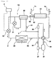
- Fig. 1 is a schematic block diagram of a refrigeration cycle apparatus according to the embodiment 1 of the invention.
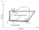
- Fig. 2 is a Mollier chart of the refrigeration cycle apparatus.
- Fig. 3 is an another Mollier chart of the refrigeration cycle apparatus.
- the refrigeration cycle apparatus 1A includes a refrigerant circuit 2 through which a refrigerant is circulated, a bypass passage 3, and a control device 4.
- a refrigerant it is possible to use a zeotropic refrigerant mixture such as R407C, a pseudo-azeotropic refrigerant mixture such as R410A or a single refrigerant.
- the refrigerant circuit 2 includes a compressor 21, a radiator 22, a supercooling heat exchanger 23, a main expansion valve (main expansion means) 24 and an evaporator 25, and these constituent members are annularly connected to one another through pipes.
- a sub-accumulator 26 and a main accumulator 27 which separate gas and liquid from each other are provided between the evaporator 25 and the compressor 21.
- the refrigerant circuit 2 is provided with a four-way valve 28 which switches between a normal operation and a defrosting operation.
- the refrigeration cycle apparatus 1A configures heating means of a hydronic heater which utilizes hot water produced by the heating means for heating a room, and the radiator 22 is a heat exchanger which exchanges heat between a refrigerant and water to heat the water.
- a supply pipe 71 and a collecting pipe 72 are connected to the radiator 22, water is supplied to the radiator 22 through the supply pipe 71, and water (hot water) heated by the radiator 22 is collected through the collecting pipe 72.
- the hot water collected through the collecting pipe 72 is sent directly to a heater, or sent to the heater through a hot water tank, thereby heating a room.
- the bypass passage 3 branches off from the refrigerant circuit 2 between the supercooling heat exchanger 23 and the main expansion valve 24, and is connected to the refrigerant circuit 2 between the sub-accumulator 26 and the main accumulator 27 between the evaporator 25 and the compressor 21 through the supercooling heat exchanger 23.
- the bypass passage 3 is provided with a bypass expansion valve (bypass expansion means) 31 at a location upstream of the supercooling heat exchanger 23.
- a refrigerant discharged from the compressor 21 is sent to the radiator 22 through the four-way valve 28.
- a refrigerant discharged from the compressor 21 is sent to the evaporator 25 through the four-way valve 28.
- arrows show a flowing direction of a refrigerant at the time of the normal operation. A state variation in a refrigerant at the time of the normal operation will be explained.
- a high-pressure refrigerant discharged from the compressor 21 flows into the radiator 22, and radiates heat to water which passes through the radiator 22.
- the high-pressure refrigerant which flows out from the radiator 22 flows into the supercooling heat exchanger 23, and the refrigerant is supercooled by a low-pressure refrigerant which is decompressed by the bypass expansion valve 31.
- the high-pressure refrigerant which flows out from the supercooling heat exchanger 23 is distributed to the main expansion valve 24 and the bypass expansion valve 31.
- the high-pressure refrigerant distributed to the main expansion valve 24 is decompressed by the main expansion valve 24 and expanded and then, the refrigerant flows into the evaporator 25.
- the low-pressure refrigerant which flows into the evaporator 25 absorbs heat from air in the evaporator 25.
- the high-pressure refrigerant distributed to the bypass expansion valve 31 is decompressed by the bypass expansion valve 31 and expanded and then, the refrigerant flows into the supercooling heat exchanger 23.
- the low-pressure refrigerant which flows into the supercooling heat exchanger 23 is heated by the high-pressure refrigerant which flows out from the radiator 22. Thereafter, the low-pressure refrigerant which flows out from the supercooling heat exchanger 23 merges with the low-pressure refrigerant which flows out from the evaporator 25, and these refrigerants are again sucked into the compressor 21.
- the configuration of the refrigeration cycle apparatus 1A of the embodiment is for avoiding a case where pressure of a refrigerant sucked into the compressor 21 is reduced when an outside air temperature is low, a refrigerant circulation amount is reduced and according to this, heating ability of the radiator 22 is deteriorated.
- the low-pressure side refrigerant circuit is a refrigerant circuit 2 extending from the main expansion valve 24 to the compressor 21.
- the control device 4 controls such that the bypass expansion valve 31 is operated to bring the outlet refrigerant into a saturated state, and when the outlet refrigerant of the bypass passage 3 is in the saturated state, the control device 4 controls such that the bypass expansion valve 31 is operated to bring a supercooling degree of the outlet of the radiator 22 into a preset predetermined supercooling degree.
- the control device 4 controls such that as the superheating degree of the evaporator 25 is greater, the predetermined supercooling degree of the outlet of the radiator 22 becomes smaller.
- a refrigerant state of the outlet of the bypass passage 3 is always controlled into saturated state as shown with points a, b and c in Fig. 2 .
- the bypass amount becomes excessively great or excessively small in some cases.
- the supercooling degree of the outlet of the radiator 22 becomes excessively great or excessively small as shown with points a' and c' in Fig. 2 due to a difference in a decompression amount of the bypass expansion valve 31. Therefore, it can be determined that the bypass amount is inappropriate.
- the bypass amount is appropriately controlled as shown with the point b in Fig. 2 .
- the refrigerant circuit 2 includes a first pressure sensor 51 which detects pressure (suction pressure) Ps of a refrigerant sucked into the compressor 21, a second pressure sensor 52 which detects a pressure (radiator outlet pressure) Pc of a refrigerant flowing out from the radiator 22, a second temperature sensor 62 which detects a temperature (radiator outlet temperature) Tco of a refrigerant flowing out from the radiator 22, a third temperature sensor 63 which detects a temperature (evaporator outlet temperature) Teo of a refrigerant flowing out from the evaporator 25 and a forth temperature sensor 64 which detects a temperature (discharge temperature) Td of a refrigerant discharged from the compressor 21.
- the bypass passage 3 includes a first temperature sensor 61 which detects a temperature (bypass passage outlet temperature) Tbo of a refrigerant flowing out from the supercooling heat exchanger 23.
- the control device 4 operates the number of rotations of the compressor 21, the switching operation of the four-way valve 28, and opening degrees of the main expansion valve 24 and the bypass expansion valve 31 based on detection values of the first pressure sensor 51, the second pressure sensor 52, the first temperature sensor 61, the second temperature sensor 62, the third temperature sensor 63 and the forth temperature sensor 64.
- Fig. 4 is a block diagram showing a control device in terms of function realizing means.
- the control device 4 includes discharge temperature comparing means 40 and main valve operation determining means 41 for operating the main expansion valve 24.
- control device 4 For operating the bypass expansion valve 31, the control device 4 includes suction saturation temperature calculating means 42, saturation temperature comparing means 43, bypass valve operation determining means 44, radiator saturation temperature calculating means 45, refrigerant supercooling degree calculating means 46, refrigerant superheating degree calculating means 47,target supercooling degree calculating means 48 and supercooling degree comparing means 49.
- the discharge temperature comparing means 40 compares a discharge temperature Td detected by the fourth temperature sensor 64 and a preset target discharge temperature Tdm with each other.
- the target discharge temperature Tdm is previously stored.
- the main valve operation determining means 41 determines an opening degree of the main expansion valve 24 such that the discharge temperature Td becomes equal to the target discharge temperature Tdm based on a result of comparison made by the discharge temperature comparing means 40, and outputs an operation amount determined for the main expansion valve 24.
- the suction saturation temperature calculating means 42 calculates a suction saturation temperature Ts under pressure of a refrigerant sucked into the compressor 21 from a suction pressure Ps detected by the first pressure sensor 51.
- the saturation temperature comparing means 43 compared, with each other, the suction saturation temperature Ts calculated by the suction saturation temperature calculating means 42 and the bypass passage outlet temperature Tbo detected by the first temperature sensor 61.
- the bypass valve operation determining means 44 determines the opening degree of the bypass expansion valve 31 such that the bypass passage outlet temperature Tbo becomes equal to the suction saturation temperature Ts, and the bypass valve operation determining means 44 outputs an operation amount determined for the bypass expansion valve 31.
- the radiator saturation temperature calculating means 45 calculates a radiator saturation temperature Tc under pressure of a refrigerant flowing out from the radiator 22 from a radiator outlet pressure Pc detected by the second pressure sensor 52.
- the refrigerant supercooling degree calculating means 46 calculates a refrigerant supercooling degree Sc (Tc-Tco) at the outlet of the radiator 22from the radiator saturation temperature Tc detected by the radiator saturation temperature calculating means 45 and from a radiator outlet temperature Tco detected by the second temperature sensor 62.
- the refrigerant superheating degree calculating means 47 calculates a refrigerant supercooling degree Sh (Teo-Ts) at the outlet of the evaporator 25 from the suction saturation temperature Ts detected by the suction saturation temperature calculating means 42 and an evaporator outlet temperature Teo detected by the third temperature sensor 63.
- the target supercooling degree calculating means 48 calculates a target supercooling degree Sct (e.g., a ⁇ Sh+b) at the outlet of the radiator 22 from the refrigerant supercooling degree Sh detected by the refrigerant superheating degree calculating means 47.
- a target supercooling degree Sct e.g., a ⁇ Sh+b
- the supercooling degree comparing means 49 compares, with each other, the refrigerant supercooling degree Sc at the outlet of the radiator 22 calculated by the refrigerant supercooling degree calculating means 46 with the target supercooling degree Sct at the outlet of the radiator 22 calculated by the target supercooling degree calculating means 48.
- the bypass valve operation determining means 44 determines the opening degree of the bypass expansion valve 31 such that the refrigerant supercooling degree Sc at the outlet of the radiator 22 calculated by the refrigerant supercooling degree calculating means 46 becomes equal to the target supercooling degree Sct at the outlet of the radiator 22 calculated by the target supercooling degree calculating means 48 based on a result of comparison carried out by the supercooling degree comparing means 49, and the bypass valve operation determining means 44 outputs an operation amount determined for the bypass expansion valve 31.
- control device 4 operates the main expansion valve 24 such that the discharge temperature Td becomes equal to a preset predetermined target temperature Tdt at the time of the normal operation.
- the control device 4 operates the bypass expansion valve 31 such that the bypass passage outlet temperature Tbo becomes equal to the suction saturation temperature Ts calculated based on the suction pressure Ps.
- the control device 4 operates the bypass expansion valve 31 such that the refrigerant supercooling degree Sc at the outlet of the radiator 22 which is obtained by a difference between the radiator outlet temperature Tco and the radiator saturation temperature Tc calculated based on the radiator outlet pressure Pc becomes equal to the target supercooling degree Sct at the outlet of the radiator 22 which is determined based on the evaporator outlet superheating degree Sh obtained by a difference between the suction saturation temperature Ts and the evaporator outlet temperature Teo.
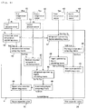
- control of the control device 4 at the time of the normal operation will be explained in detail with reference to the flowchart shown in Fig. 4 .
- control device 4 detects the discharge temperature Td by the fourth temperature sensor 64 (step 1), and operates the main expansion valve 24 such that the discharge temperature Td becomes equal to the preset target discharge temperature Tdm (step 2).
- the control device 4 detects the suction pressure Ps by the first pressure sensor 51 and detects the bypass passage outlet temperature Tbo by the first temperature sensor 61 (step 3) . Then, the control device 4 calculates the suction saturation temperature Ts under a pressure of a refrigerant sucked into the compressor 21 from the suction pressure Ps detected by the first pressure sensor 51 (step 4). The suction saturation temperature Ts is calculated using a refrigerant-properties equation.
- the control device 4 compares the bypass passage outlet temperature Tbo and the suction saturation temperature Ts with each other, and determines whether Tbo and Ts are equal to each other (step 5). If the bypass passage outlet temperature Tbo is not equal to the suction saturation temperature Ts (NO in step 5), the control device 4 determines that a bypass passage outlet refrigerant is in a superheated state, and the control device 4 adjusts the opening degree of the bypass expansion valve 31 such that the bypass passage outlet temperature Tbo becomes equal to the suction saturation temperature Ts (step 6), and the procedure returns to step 1.
- the control device 4 determines that the bypass passage outlet refrigerant is in the saturated state, and the procedure is shifted to a control step where the bypass amount is optimized.
- the second pressure sensor 52 detects the radiator outlet pressure Pc
- the second temperature sensor 62 detects the radiator outlet temperature Tco
- the third temperature sensor 63 detects the evaporator outlet temperature Teo (step 7).
- the radiator saturation temperature Tc under a pressure of a refrigerant flowing out from the radiator 22 is calculated from the radiator outlet pressure Pc detected by the second pressure sensor 52 (step 8).
- the radiator saturation temperature Tc is also calculated using the refrigerant-properties equation.
- a and b are coefficients, and a is a positive real number.
- the control device 4 adjusts the opening degree of the bypass expansion valve 31 such that the refrigerant supercooling degree Sc at the outlet of the radiator 22 becomes equal to the target supercooling degree Sct at the outlet of the radiator 22 (step 11), and the procedure returns to step 1.
- the refrigerant circuit 2 includes the first pressure sensor 51 which detects a pressure of a refrigerant sucked into the compressor 21, the second pressure sensor 52 which detects a pressure of a refrigerant flowing out from the radiator 22, the second temperature sensor 62 which detects a temperature of the refrigerant flowing out from the radiator 22, the third temperature sensor 63 which detects a temperature of a refrigerant flowing out from the evaporator 25, the fourth temperature sensor 64 which detects a temperature of a refrigerant discharged from the compressor 21, and the first temperature sensor 61 which detects a temperature of a refrigerant flowing out from the supercooling heat exchanger 23 in the bypass passage 3.
- the control device 4 operates the main expansion valve 24 such that the discharge temperature Td detected by the fourth temperature sensor 64 becomes equal to the predetermined target temperature Tdt, and if the bypass passage outlet temperature Tbo detected by the first temperature sensor 61 is not equal to the suction saturation temperature Ts calculated based on the suction pressure Ps detected by the first pressure sensor 51, the control device 4 operates the bypass expansion valve 31 such that the bypass passage outlet temperature Tbo becomes equal to the suction saturation temperature Ts.
- the control device 4 When the bypass passage outlet temperature Tbo is substantially equal to the suction saturation temperature Ts, the control device 4 operates the bypass expansion valve 31 such that the refrigerant supercooling degree Sc at the outlet of the radiator 22 obtained by a difference between the radiator outlet temperature Tco and the radiator saturation temperature Tc which is calculated based on the radiator outlet pressure Pc detected by the second pressure sensor 52 becomes equal to the target supercooling degree Sct at the outlet of the radiator 22 determined based on the evaporator outlet superheating degree Sh obtained by a difference between the suction saturation temperature Ts and the evaporator outlet temperature Teo.
- control is performed such that the refrigerant at the outlet of the bypass passage 3 is always brought into the saturated state and when the refrigerant at the outlet of the bypass passage 3 is in the saturated state, a supercooling degree at the outlet of a radiator 22 is appropriately controlled.
- a bypass amount can be optimized.
- the first pressure sensor 51 is provided between the main accumulator 27 and the position of the refrigerant circuit 2 to which the bypass passage 3 is connected in Fig. 1
- the first pressure sensor 51 may be provided at any position of the refrigerant circuit 2 only if the first pressure sensor 51 is provided between the evaporator 25 and the compressor 21.
- the first pressure sensor 51 may be provided at the bypass passage 3 at a location downstream of the supercooling heat exchanger 23.
- the first pressure sensor 51 calculates the suction saturation temperature Ts in the embodiment, temperatures in the refrigerant circuit 2 and the bypass passage 3 at portions through which low pressure two-phase refrigerants flow may be detected and the detected values may be used as the suction saturation temperature Ts.
- the second pressure sensor 52 is provided at a position of the outlet of the radiator 22 in the refrigerant circuit 2, but the second pressure sensor 52 may be provided at any position of the refrigerant circuit 2 only if the position is between the compressor 21 and the main expansion valve 24. It is more preferable if a pressure loss between the position of the outlet of the radiator 22 and the position of the second pressure sensor 52 is calculated from a flow rate of a refrigerant and the loss is corrected.
- radiator saturation temperature Tc is calculated by the second pressure sensor 52, a temperature of a portion where a high pressure two-phase refrigerant in the radiator 22 flows may be detected and a result thereof may be used instead of the radiator saturation temperature Tc.
- bypass passage 3 branches off from the refrigerant circuit 2 between the supercooling heat exchanger 23 and the main expansion valve 24, and the bypass passage 3 may branch off from the refrigerant circuit 2 between the radiator 22 and the supercooling heat exchanger 23.
- connection of the bypass passage 3 is a suction pipe of the compressor 21.
- the connection of the bypass passage 3 may be connected to an injection port.
- main expansion valve 24 and the bypass expansion valve 31 of the invention are expansion valves, and they may be expansion devices which collect power from an expanding refrigerant.
- the number of rotations of the expansion device may be control by varying a load by means of a power generator connected to the expansion device.
- the present invention is especially effective for a hydronic heater which produces hot water by a refrigeration cycle apparatus and utilizes the hot water for heating a room.
Landscapes
- Engineering & Computer Science (AREA)
- Physics & Mathematics (AREA)
- Mechanical Engineering (AREA)
- Thermal Sciences (AREA)
- General Engineering & Computer Science (AREA)
- Air Conditioning Control Device (AREA)
- Steam Or Hot-Water Central Heating Systems (AREA)
- Compression-Type Refrigeration Machines With Reversible Cycles (AREA)
- Devices That Are Associated With Refrigeration Equipment (AREA)
Claims (3)
- Dispositif à cycle frigorifique (1A) comprenant:un circuit frigorifique (2) dans lequel un compresseur (21), un radiateur (22), un échangeur de chaleur de super-réfrigération (23), des moyens principaux de détente (24) et un évaporateur (25) sont reliés, dans cet ordre, de façon annulaire les uns aux autres,un canal de dérivation (3) qui est en dérivation du circuit frigorifique entre ledit radiateur et lesdits moyens principaux de détente et qui est relié au circuit frigorifique entre l'évaporateur et le compresseur ou est relié à une chambre de ,compression du compresseur par ledit échangeur de chaleur de super-réfrigération,des moyens de détente de dérivation (31) prévus dans le canal de dérivation à un endroit situé en amont de l'échangeur de chaleur de super-réfrigération,un premier capteur de température (61) qui détecte une température d'un réfrigérant sortant de l'échangeur de chaleur de super-réfrigération (23),des premiers moyens de détection de température de saturation (51) qui détectent une température de saturation d'un réfrigérant aspiré dans le compresseur,un deuxième capteur de température (62) qui détecte une température d'un réfrigérant sortant du radiateur, etdes deuxièmes moyens de détection de température de saturation (52) qui détectent une température de saturation du réfrigérant dans le radiateur,caractérisé par le fait qu'un dispositif de commande (4) actionne les moyens de détente de dérivation de telle sorte qu'une température détectée par le premier capteur de température se rapproche d'une température détectée par les premiers moyens de détection de température de saturation, lorsque la température détectée par le premier capteur de température est supérieure à la température détectée par les premiers moyens de détection de température de saturation, et le dispositif de commande actionne les moyens de détente de dérivation de telle sorte qu'une température détectée par le deuxième capteur de température devient inférieure d'une température prédéterminée à une température détectée par les deuxièmes moyens de détection de température de saturation, lorsque la température détectée par le premier capteur de température est pour l'essentiel égale à la température détectée par les premiers moyens de détection de température de saturation.
- Dispositif à cycle frigorifique selon la revendication 1,
comprenant en outre:un troisième capteur de température qui détecte une température d'un réfrigérant sortant de l'évaporateur,caractérisé par le fait que le dispositif de commande commande de telle sorte que, lorsqu'une différence de température entre une température détectée par le troisième capteur de température et la température détectée par les premiers moyens de détection de température de saturation devient plus grande, une valeur de la température prédéterminée devient plus petite. - Dispositif de chauffage hydraulique comprenant le dispositif à cycle frigorifique selon la revendication 1 ou 2.
Applications Claiming Priority (1)
| Application Number | Priority Date | Filing Date | Title |
|---|---|---|---|
| JP2011085142A JP5637053B2 (ja) | 2011-04-07 | 2011-04-07 | 冷凍サイクル装置及びそれを備えた温水暖房装置 |
Publications (3)
| Publication Number | Publication Date |
|---|---|
| EP2508821A2 EP2508821A2 (fr) | 2012-10-10 |
| EP2508821A3 EP2508821A3 (fr) | 2015-02-11 |
| EP2508821B1 true EP2508821B1 (fr) | 2016-02-24 |
Family
ID=45954479
Family Applications (1)
| Application Number | Title | Priority Date | Filing Date |
|---|---|---|---|
| EP12163185.7A Active EP2508821B1 (fr) | 2011-04-07 | 2012-04-04 | Appareil de cycle de réfrigération et dispositif de chauffage hydronique utilisant l'appareil de cycle de réfrigération |
Country Status (3)
| Country | Link |
|---|---|
| EP (1) | EP2508821B1 (fr) |
| JP (1) | JP5637053B2 (fr) |
| CN (1) | CN102734969B (fr) |
Families Citing this family (14)
| Publication number | Priority date | Publication date | Assignee | Title |
|---|---|---|---|---|
| JP2014105890A (ja) * | 2012-11-26 | 2014-06-09 | Panasonic Corp | 冷凍サイクル装置及びそれを備えた温水生成装置 |
| FR3004784B1 (fr) * | 2013-04-18 | 2015-04-10 | Air Liquide | Procede et installation d'alimentation d'au moins un poste d'usinage en liquide cryogenique sous-refroidi |
| JP6125325B2 (ja) * | 2013-05-20 | 2017-05-10 | サンデンホールディングス株式会社 | 車両用空気調和装置 |
| CN105683681A (zh) * | 2013-10-28 | 2016-06-15 | 三菱电机株式会社 | 制冷循环装置 |
| CN104729162B (zh) * | 2013-12-24 | 2018-02-27 | 珠海格力电器股份有限公司 | 冷却系统及具有该冷却系统的空调器 |
| CN104896793A (zh) * | 2014-03-06 | 2015-09-09 | 珠海格力电器股份有限公司 | 空调热水机系统 |
| JP6339036B2 (ja) * | 2015-03-17 | 2018-06-06 | ヤンマー株式会社 | ヒートポンプ |
| JP6643627B2 (ja) * | 2015-07-30 | 2020-02-12 | パナソニックIpマネジメント株式会社 | 熱生成ユニット |
| JP2017155944A (ja) * | 2016-02-29 | 2017-09-07 | パナソニックIpマネジメント株式会社 | 冷凍サイクル装置及びそれを備えた温水暖房装置 |
| US10488089B2 (en) * | 2016-10-05 | 2019-11-26 | Johnson Controls Technology Company | Parallel capillary expansion tube systems and methods |
| CN115342539A (zh) * | 2021-05-14 | 2022-11-15 | 浙江三花汽车零部件有限公司 | 制冷系统、膨胀阀组件以及制冷系统控制方法 |
| DE102021126839A1 (de) | 2021-10-15 | 2023-04-20 | Audi Aktiengesellschaft | Betriebsverfahren (Umleitung) für eine Kälteanlage im Wärmepumpenbetrieb bei tiefen Umgebungstemperaturen, Kälteanlage und Kraftfahrzeug mit einer derart betriebenen Kälteanlage |
| DE102021126837A1 (de) | 2021-10-15 | 2023-04-20 | Audi Aktiengesellschaft | Betriebsverfahren für eine Kälteanlage im Wärmepumpenbetrieb bei tiefen Umgebungstemperaturen und Kraftfahrzeug mit einer derart betriebenen Kälteanlage |
| WO2024072876A2 (fr) * | 2022-09-28 | 2024-04-04 | Energy Recovery, Inc. | Commande d'architectures de système de réfrigération et de pompe à chaleur qui comprennent des échangeurs de pression |
Family Cites Families (9)
| Publication number | Priority date | Publication date | Assignee | Title |
|---|---|---|---|---|
| JPH1068553A (ja) | 1996-08-27 | 1998-03-10 | Daikin Ind Ltd | 空気調和機 |
| JP3757967B2 (ja) * | 2003-08-25 | 2006-03-22 | ダイキン工業株式会社 | 冷凍装置 |
| JP3963190B2 (ja) * | 2005-04-07 | 2007-08-22 | ダイキン工業株式会社 | 空気調和装置の冷媒量判定システム |
| CN1896646A (zh) * | 2005-07-11 | 2007-01-17 | 海尔集团公司 | 空调制冷剂过冷度的控制装置及其控制方法 |
| JP4114691B2 (ja) * | 2005-12-16 | 2008-07-09 | ダイキン工業株式会社 | 空気調和装置 |
| JP2008082601A (ja) * | 2006-09-27 | 2008-04-10 | Matsushita Electric Ind Co Ltd | ヒートポンプ給湯装置 |
| CN101153760A (zh) * | 2006-09-30 | 2008-04-02 | 海尔集团公司 | 空调回热装置及其控制方法 |
| JP2010091135A (ja) * | 2008-10-03 | 2010-04-22 | Tokyo Electric Power Co Inc:The | 二段圧縮式給湯装置およびその起動制御方法 |
| KR20110004152A (ko) * | 2009-07-07 | 2011-01-13 | 엘지전자 주식회사 | 공기조화기 |
-
2011
- 2011-04-07 JP JP2011085142A patent/JP5637053B2/ja active Active
-
2012
- 2012-04-04 EP EP12163185.7A patent/EP2508821B1/fr active Active
- 2012-04-09 CN CN201210101651.0A patent/CN102734969B/zh active Active
Also Published As
| Publication number | Publication date |
|---|---|
| JP5637053B2 (ja) | 2014-12-10 |
| CN102734969A (zh) | 2012-10-17 |
| JP2012220072A (ja) | 2012-11-12 |
| CN102734969B (zh) | 2016-03-09 |
| EP2508821A2 (fr) | 2012-10-10 |
| EP2508821A3 (fr) | 2015-02-11 |
Similar Documents
| Publication | Publication Date | Title |
|---|---|---|
| EP2508821A2 (fr) | Appareil de cycle de réfrigération et dispositif de chauffage hydronique utilisant l'appareil de cycle de réfrigération | |
| EP2482014B1 (fr) | Appareil à cycle de réfrigération et chauffage hydronique utilisant ledit appareil | |
| EP2535674B1 (fr) | Appareil de cycle de réfrigération et dispositif de chauffage hydronique utilisant l'appareil de cycle de réfrigération | |
| EP2434233B1 (fr) | Appareil à cycle de réfrigération et appareil de chauffage d'eau chaude | |
| EP2924375B1 (fr) | Dispositif à cycle de réfrigération et dispositif de production d'eau chaude équipé de celui-ci | |
| CN104296245B (zh) | 空调机及其控制方法 | |
| KR101598624B1 (ko) | 공기 조화 시스템 | |
| JP6161005B2 (ja) | 冷凍サイクル装置およびそれを備えた温水生成装置 | |
| EP2735819B1 (fr) | Appareil à cycle de réfrigération et appareil de production d'eau chaude disposant d'un appareil à cycle de réfrigération | |
| EP2933583A1 (fr) | Dispositif de chauffage du type pompe à chaleur | |
| EP3211350B1 (fr) | Dispositif à cycle de réfrigération et difspositif de chauffage d'eau doté de celui-ci | |
| EP2873934A1 (fr) | Dispositif chauffant de type pompe à chaleur | |
| EP2607809B1 (fr) | Chauffage hydronique | |
| EP2482013A2 (fr) | Appareil à cycle de réfrigération | |
| JP6246394B2 (ja) | 空気調和装置 | |
| JP2011185507A (ja) | 冷凍サイクル装置およびそれを備えた温水暖房装置 | |
| EP2918921B1 (fr) | Générateur d'eau chaude | |
| JP5233960B2 (ja) | 冷凍サイクル装置及びそれを用いた温水暖房装置 | |
| EP3220078A1 (fr) | Dispositif à cycle de réfrigération et dispositif de chauffage d'eau doté de celui-ci | |
| EP2538159A2 (fr) | Appareil à cycle de réfrigération et appareil de chauffage hydronique comportant l'appareil à cycle de réfrigération | |
| JP2013002801A (ja) | 冷凍サイクル装置及びそれを備えた温水暖房装置 | |
| WO2026105356A1 (fr) | Dispositif à cycle frigorifique et procédé de commande de dispositif à cycle frigorifique |
Legal Events
| Date | Code | Title | Description |
|---|---|---|---|
| PUAI | Public reference made under article 153(3) epc to a published international application that has entered the european phase |
Free format text: ORIGINAL CODE: 0009012 |
|
| AK | Designated contracting states |
Kind code of ref document: A2 Designated state(s): AL AT BE BG CH CY CZ DE DK EE ES FI FR GB GR HR HU IE IS IT LI LT LU LV MC MK MT NL NO PL PT RO RS SE SI SK SM TR |
|
| AX | Request for extension of the european patent |
Extension state: BA ME |
|
| PUAL | Search report despatched |
Free format text: ORIGINAL CODE: 0009013 |
|
| AK | Designated contracting states |
Kind code of ref document: A3 Designated state(s): AL AT BE BG CH CY CZ DE DK EE ES FI FR GB GR HR HU IE IS IT LI LT LU LV MC MK MT NL NO PL PT RO RS SE SI SK SM TR |
|
| AX | Request for extension of the european patent |
Extension state: BA ME |
|
| RIC1 | Information provided on ipc code assigned before grant |
Ipc: F25B 40/02 20060101ALI20150107BHEP Ipc: F25B 49/02 20060101AFI20150107BHEP |
|
| 17P | Request for examination filed |
Effective date: 20150421 |
|
| RBV | Designated contracting states (corrected) |
Designated state(s): AL AT BE BG CH CY CZ DE DK EE ES FI FR GB GR HR HU IE IS IT LI LT LU LV MC MK MT NL NO PL PT RO RS SE SI SK SM TR |
|
| GRAP | Despatch of communication of intention to grant a patent |
Free format text: ORIGINAL CODE: EPIDOSNIGR1 |
|
| INTG | Intention to grant announced |
Effective date: 20150730 |
|
| GRAS | Grant fee paid |
Free format text: ORIGINAL CODE: EPIDOSNIGR3 |
|
| GRAA | (expected) grant |
Free format text: ORIGINAL CODE: 0009210 |
|
| AK | Designated contracting states |
Kind code of ref document: B1 Designated state(s): AL AT BE BG CH CY CZ DE DK EE ES FI FR GB GR HR HU IE IS IT LI LT LU LV MC MK MT NL NO PL PT RO RS SE SI SK SM TR |
|
| REG | Reference to a national code |
Ref country code: GB Ref legal event code: FG4D |
|
| REG | Reference to a national code |
Ref country code: CH Ref legal event code: EP |
|
| REG | Reference to a national code |
Ref country code: AT Ref legal event code: REF Ref document number: 776937 Country of ref document: AT Kind code of ref document: T Effective date: 20160315 |
|
| REG | Reference to a national code |
Ref country code: IE Ref legal event code: FG4D |
|
| REG | Reference to a national code |
Ref country code: DE Ref legal event code: R096 Ref document number: 602012014835 Country of ref document: DE |
|
| REG | Reference to a national code |
Ref country code: FR Ref legal event code: PLFP Year of fee payment: 5 |
|
| REG | Reference to a national code |
Ref country code: LT Ref legal event code: MG4D |
|
| REG | Reference to a national code |
Ref country code: NL Ref legal event code: MP Effective date: 20160224 |
|
| REG | Reference to a national code |
Ref country code: AT Ref legal event code: MK05 Ref document number: 776937 Country of ref document: AT Kind code of ref document: T Effective date: 20160224 |
|
| PG25 | Lapsed in a contracting state [announced via postgrant information from national office to epo] |
Ref country code: NO Free format text: LAPSE BECAUSE OF FAILURE TO SUBMIT A TRANSLATION OF THE DESCRIPTION OR TO PAY THE FEE WITHIN THE PRESCRIBED TIME-LIMIT Effective date: 20160524 Ref country code: FI Free format text: LAPSE BECAUSE OF FAILURE TO SUBMIT A TRANSLATION OF THE DESCRIPTION OR TO PAY THE FEE WITHIN THE PRESCRIBED TIME-LIMIT Effective date: 20160224 Ref country code: GR Free format text: LAPSE BECAUSE OF FAILURE TO SUBMIT A TRANSLATION OF THE DESCRIPTION OR TO PAY THE FEE WITHIN THE PRESCRIBED TIME-LIMIT Effective date: 20160525 Ref country code: IT Free format text: LAPSE BECAUSE OF FAILURE TO SUBMIT A TRANSLATION OF THE DESCRIPTION OR TO PAY THE FEE WITHIN THE PRESCRIBED TIME-LIMIT Effective date: 20160224 Ref country code: ES Free format text: LAPSE BECAUSE OF FAILURE TO SUBMIT A TRANSLATION OF THE DESCRIPTION OR TO PAY THE FEE WITHIN THE PRESCRIBED TIME-LIMIT Effective date: 20160224 Ref country code: HR Free format text: LAPSE BECAUSE OF FAILURE TO SUBMIT A TRANSLATION OF THE DESCRIPTION OR TO PAY THE FEE WITHIN THE PRESCRIBED TIME-LIMIT Effective date: 20160224 |
|
| PG25 | Lapsed in a contracting state [announced via postgrant information from national office to epo] |
Ref country code: SE Free format text: LAPSE BECAUSE OF FAILURE TO SUBMIT A TRANSLATION OF THE DESCRIPTION OR TO PAY THE FEE WITHIN THE PRESCRIBED TIME-LIMIT Effective date: 20160224 Ref country code: PL Free format text: LAPSE BECAUSE OF FAILURE TO SUBMIT A TRANSLATION OF THE DESCRIPTION OR TO PAY THE FEE WITHIN THE PRESCRIBED TIME-LIMIT Effective date: 20160224 Ref country code: BE Free format text: LAPSE BECAUSE OF NON-PAYMENT OF DUE FEES Effective date: 20160430 Ref country code: AT Free format text: LAPSE BECAUSE OF FAILURE TO SUBMIT A TRANSLATION OF THE DESCRIPTION OR TO PAY THE FEE WITHIN THE PRESCRIBED TIME-LIMIT Effective date: 20160224 Ref country code: RS Free format text: LAPSE BECAUSE OF FAILURE TO SUBMIT A TRANSLATION OF THE DESCRIPTION OR TO PAY THE FEE WITHIN THE PRESCRIBED TIME-LIMIT Effective date: 20160224 Ref country code: LT Free format text: LAPSE BECAUSE OF FAILURE TO SUBMIT A TRANSLATION OF THE DESCRIPTION OR TO PAY THE FEE WITHIN THE PRESCRIBED TIME-LIMIT Effective date: 20160224 Ref country code: PT Free format text: LAPSE BECAUSE OF FAILURE TO SUBMIT A TRANSLATION OF THE DESCRIPTION OR TO PAY THE FEE WITHIN THE PRESCRIBED TIME-LIMIT Effective date: 20160624 Ref country code: LV Free format text: LAPSE BECAUSE OF FAILURE TO SUBMIT A TRANSLATION OF THE DESCRIPTION OR TO PAY THE FEE WITHIN THE PRESCRIBED TIME-LIMIT Effective date: 20160224 Ref country code: NL Free format text: LAPSE BECAUSE OF FAILURE TO SUBMIT A TRANSLATION OF THE DESCRIPTION OR TO PAY THE FEE WITHIN THE PRESCRIBED TIME-LIMIT Effective date: 20160224 |
|
| PG25 | Lapsed in a contracting state [announced via postgrant information from national office to epo] |
Ref country code: DK Free format text: LAPSE BECAUSE OF FAILURE TO SUBMIT A TRANSLATION OF THE DESCRIPTION OR TO PAY THE FEE WITHIN THE PRESCRIBED TIME-LIMIT Effective date: 20160224 Ref country code: EE Free format text: LAPSE BECAUSE OF FAILURE TO SUBMIT A TRANSLATION OF THE DESCRIPTION OR TO PAY THE FEE WITHIN THE PRESCRIBED TIME-LIMIT Effective date: 20160224 |
|
| REG | Reference to a national code |
Ref country code: DE Ref legal event code: R097 Ref document number: 602012014835 Country of ref document: DE |
|
| PG25 | Lapsed in a contracting state [announced via postgrant information from national office to epo] |
Ref country code: SM Free format text: LAPSE BECAUSE OF FAILURE TO SUBMIT A TRANSLATION OF THE DESCRIPTION OR TO PAY THE FEE WITHIN THE PRESCRIBED TIME-LIMIT Effective date: 20160224 Ref country code: RO Free format text: LAPSE BECAUSE OF FAILURE TO SUBMIT A TRANSLATION OF THE DESCRIPTION OR TO PAY THE FEE WITHIN THE PRESCRIBED TIME-LIMIT Effective date: 20160224 Ref country code: CZ Free format text: LAPSE BECAUSE OF FAILURE TO SUBMIT A TRANSLATION OF THE DESCRIPTION OR TO PAY THE FEE WITHIN THE PRESCRIBED TIME-LIMIT Effective date: 20160224 Ref country code: SK Free format text: LAPSE BECAUSE OF FAILURE TO SUBMIT A TRANSLATION OF THE DESCRIPTION OR TO PAY THE FEE WITHIN THE PRESCRIBED TIME-LIMIT Effective date: 20160224 |
|
| REG | Reference to a national code |
Ref country code: CH Ref legal event code: PL |
|
| PG25 | Lapsed in a contracting state [announced via postgrant information from national office to epo] |
Ref country code: BE Free format text: LAPSE BECAUSE OF FAILURE TO SUBMIT A TRANSLATION OF THE DESCRIPTION OR TO PAY THE FEE WITHIN THE PRESCRIBED TIME-LIMIT Effective date: 20160224 Ref country code: LU Free format text: LAPSE BECAUSE OF FAILURE TO SUBMIT A TRANSLATION OF THE DESCRIPTION OR TO PAY THE FEE WITHIN THE PRESCRIBED TIME-LIMIT Effective date: 20160404 |
|
| PLBE | No opposition filed within time limit |
Free format text: ORIGINAL CODE: 0009261 |
|
| STAA | Information on the status of an ep patent application or granted ep patent |
Free format text: STATUS: NO OPPOSITION FILED WITHIN TIME LIMIT |
|
| GBPC | Gb: european patent ceased through non-payment of renewal fee |
Effective date: 20160524 |
|
| REG | Reference to a national code |
Ref country code: IE Ref legal event code: MM4A |
|
| PG25 | Lapsed in a contracting state [announced via postgrant information from national office to epo] |
Ref country code: LI Free format text: LAPSE BECAUSE OF NON-PAYMENT OF DUE FEES Effective date: 20160430 Ref country code: CH Free format text: LAPSE BECAUSE OF NON-PAYMENT OF DUE FEES Effective date: 20160430 |
|
| 26N | No opposition filed |
Effective date: 20161125 |
|
| PG25 | Lapsed in a contracting state [announced via postgrant information from national office to epo] |
Ref country code: SI Free format text: LAPSE BECAUSE OF FAILURE TO SUBMIT A TRANSLATION OF THE DESCRIPTION OR TO PAY THE FEE WITHIN THE PRESCRIBED TIME-LIMIT Effective date: 20160224 Ref country code: BG Free format text: LAPSE BECAUSE OF FAILURE TO SUBMIT A TRANSLATION OF THE DESCRIPTION OR TO PAY THE FEE WITHIN THE PRESCRIBED TIME-LIMIT Effective date: 20160524 |
|
| REG | Reference to a national code |
Ref country code: FR Ref legal event code: PLFP Year of fee payment: 6 |
|
| PG25 | Lapsed in a contracting state [announced via postgrant information from national office to epo] |
Ref country code: GB Free format text: LAPSE BECAUSE OF NON-PAYMENT OF DUE FEES Effective date: 20160524 Ref country code: IE Free format text: LAPSE BECAUSE OF NON-PAYMENT OF DUE FEES Effective date: 20160404 |
|
| REG | Reference to a national code |
Ref country code: FR Ref legal event code: PLFP Year of fee payment: 7 |
|
| PG25 | Lapsed in a contracting state [announced via postgrant information from national office to epo] |
Ref country code: CY Free format text: LAPSE BECAUSE OF FAILURE TO SUBMIT A TRANSLATION OF THE DESCRIPTION OR TO PAY THE FEE WITHIN THE PRESCRIBED TIME-LIMIT Effective date: 20160224 Ref country code: HU Free format text: LAPSE BECAUSE OF FAILURE TO SUBMIT A TRANSLATION OF THE DESCRIPTION OR TO PAY THE FEE WITHIN THE PRESCRIBED TIME-LIMIT; INVALID AB INITIO Effective date: 20120404 |
|
| PG25 | Lapsed in a contracting state [announced via postgrant information from national office to epo] |
Ref country code: TR Free format text: LAPSE BECAUSE OF FAILURE TO SUBMIT A TRANSLATION OF THE DESCRIPTION OR TO PAY THE FEE WITHIN THE PRESCRIBED TIME-LIMIT Effective date: 20160224 Ref country code: MC Free format text: LAPSE BECAUSE OF FAILURE TO SUBMIT A TRANSLATION OF THE DESCRIPTION OR TO PAY THE FEE WITHIN THE PRESCRIBED TIME-LIMIT Effective date: 20160224 Ref country code: IS Free format text: LAPSE BECAUSE OF FAILURE TO SUBMIT A TRANSLATION OF THE DESCRIPTION OR TO PAY THE FEE WITHIN THE PRESCRIBED TIME-LIMIT Effective date: 20160224 Ref country code: MK Free format text: LAPSE BECAUSE OF FAILURE TO SUBMIT A TRANSLATION OF THE DESCRIPTION OR TO PAY THE FEE WITHIN THE PRESCRIBED TIME-LIMIT Effective date: 20160224 Ref country code: MT Free format text: LAPSE BECAUSE OF NON-PAYMENT OF DUE FEES Effective date: 20160430 |
|
| PG25 | Lapsed in a contracting state [announced via postgrant information from national office to epo] |
Ref country code: AL Free format text: LAPSE BECAUSE OF FAILURE TO SUBMIT A TRANSLATION OF THE DESCRIPTION OR TO PAY THE FEE WITHIN THE PRESCRIBED TIME-LIMIT Effective date: 20160224 |
|
| PGFP | Annual fee paid to national office [announced via postgrant information from national office to epo] |
Ref country code: DE Payment date: 20250422 Year of fee payment: 14 |
|
| PGFP | Annual fee paid to national office [announced via postgrant information from national office to epo] |
Ref country code: FR Payment date: 20250425 Year of fee payment: 14 |