EP2509083B1 - Spannungstransformator - Google Patents
Spannungstransformator Download PDFInfo
- Publication number
- EP2509083B1 EP2509083B1 EP10834496.1A EP10834496A EP2509083B1 EP 2509083 B1 EP2509083 B1 EP 2509083B1 EP 10834496 A EP10834496 A EP 10834496A EP 2509083 B1 EP2509083 B1 EP 2509083B1
- Authority
- EP
- European Patent Office
- Prior art keywords
- voltage
- terminal
- secondary winding
- turns
- secondary windings
- Prior art date
- Legal status (The legal status is an assumption and is not a legal conclusion. Google has not performed a legal analysis and makes no representation as to the accuracy of the status listed.)
- Active
Links
Images


Classifications
-
- H—ELECTRICITY
- H01—ELECTRIC ELEMENTS
- H01F—MAGNETS; INDUCTANCES; TRANSFORMERS; SELECTION OF MATERIALS FOR THEIR MAGNETIC PROPERTIES
- H01F29/00—Variable transformers or inductances not covered by group H01F21/00
- H01F29/02—Variable transformers or inductances not covered by group H01F21/00 with tappings on coil or winding; with provision for rearrangement or interconnection of windings
-
- B—PERFORMING OPERATIONS; TRANSPORTING
- B60—VEHICLES IN GENERAL
- B60L—PROPULSION OF ELECTRICALLY-PROPELLED VEHICLES; SUPPLYING ELECTRIC POWER FOR AUXILIARY EQUIPMENT OF ELECTRICALLY-PROPELLED VEHICLES; ELECTRODYNAMIC BRAKE SYSTEMS FOR VEHICLES IN GENERAL; MAGNETIC SUSPENSION OR LEVITATION FOR VEHICLES; MONITORING OPERATING VARIABLES OF ELECTRICALLY-PROPELLED VEHICLES; ELECTRIC SAFETY DEVICES FOR ELECTRICALLY-PROPELLED VEHICLES
- B60L9/00—Electric propulsion with power supply external to the vehicle
- B60L9/16—Electric propulsion with power supply external to the vehicle using AC induction motors
-
- B—PERFORMING OPERATIONS; TRANSPORTING
- B60—VEHICLES IN GENERAL
- B60L—PROPULSION OF ELECTRICALLY-PROPELLED VEHICLES; SUPPLYING ELECTRIC POWER FOR AUXILIARY EQUIPMENT OF ELECTRICALLY-PROPELLED VEHICLES; ELECTRODYNAMIC BRAKE SYSTEMS FOR VEHICLES IN GENERAL; MAGNETIC SUSPENSION OR LEVITATION FOR VEHICLES; MONITORING OPERATING VARIABLES OF ELECTRICALLY-PROPELLED VEHICLES; ELECTRIC SAFETY DEVICES FOR ELECTRICALLY-PROPELLED VEHICLES
- B60L2200/00—Type of vehicles
- B60L2200/26—Rail vehicles
Definitions
- the present invention relates to a voltage transforming apparatus, and particularly to a voltage transforming apparatus converting each of several types of alternating-current (AC) voltages into a desirable voltage.
- AC alternating-current
- Japanese Patent Laid-Open JP-A-63 209 113 discloses a tap changer for changing the turns ratio in the transformer, which is configured for suppressing the oscillating voltage generated by a surge voltage.
- WO 2009/110061 discloses a voltage transforming apparatus to be mounted in a vehicle.
- the voltage transforming apparatus comprises a primary winding receiving an AC voltage, a plurality of secondary windings, and a voltage conversion circuit for converting an AC voltage induced in each of the plurality of secondary windings into a desirable voltage.
- Each of the secondary windings has a first terminal and a second terminal each having a potential that is not fixed. The first terminal and the second terminal being separately provided in each of the secondary windings.
- the voltage transforming apparatus further comprises a switching circuit.
- An iron core is provided having a main leg around which the primary winding and the plurality of secondary windings are wound.
- a side leg is connected to the main leg so as to surround the primary winding and the plurality of secondary windings.
- the first and second secondary windings are wound around the main leg so as to sandwich the primary winding.
- the terminal through which a voltage is extracted should be selected in accordance with the voltage supplied to the vehicle.
- an induction voltage is generated also at the open end, that is, at the terminal of the secondary winding that is not used.
- An object of the present invention is to provide a voltage transforming apparatus that can convert several types of AC voltages and can be reduced in size and weight.
- a voltage transforming apparatus according to the present invention is defined in claim 1.
- the present invention allows implementation of a voltage transforming apparatus that can convert several types of AC voltages and can be reduced in size and weight.
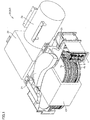
- FIG. 1 is a diagram showing an example of the configuration of a transformer according to the first embodiment of the present invention.
- the transformer according to the first embodiment is mounted in a railroad vehicle.
- a transformer 51 includes a primary winding (high-voltage side coil) 3, a secondary windings (low-voltage side coils) 4a and 4b, a terminal 9, an iron core 10, and a tank 21.
- Tank 21 houses primary winding 3, secondary windings 4a and 4b, and iron core 10.
- Tank 21 is filled with insulation oil (not shown).
- Secondary windings 4a and 4b each have terminal 9.
- Transformer 51 further includes a motor-driven blower 22, a cooler 23 and a conservator 24.
- Motor-driven blower 22 blows air into cooler 23 for cooling the insulation oil within transformer 51 (tank 21).
- Cooler 23 cools the insulation oil within transformer 51 (tank 21).
- the wind caused during running of the railroad vehicle may be introduced into cooler 23.
- motor-driven blower 22 may be omitted from the configuration shown in FIG. 1 .
- Conservator 24 is inflated or deflated by the change of the volume of the insulation oil.
- the volume of the insulation oil is increased.
- conservator 24 is inflated.
- the temperature of the insulation oil is lowered, the volume of the insulation oil is reduced. In this case, conservator 24 is deflated.
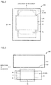
- FIGs. 2 and 3 each are a diagram schematically showing the arrangement of the transformer in the railroad vehicle shown in FIG. 1 .
- FIG. 2 is a perspective view of the transformer as seen from above the railroad vehicle.
- FIG. 3 is a diagram showing the transformer as seen from the side of the railroad vehicle. It is to be noted that FIGs. 2 and 3 each representatively show tank 21, iron core 10 and windings (primary winding 3 and secondary windings 4a, 4b) of the components shown in FIG. 1 .
- a railroad vehicle 200 has a vehicle body 211 and transformer 51. Transformer 51 is disposed below a floor 212 of vehicle body 211.
- FIG. 4 is a perspective view of the iron core, the primary winding and the secondary winding shown in FIG. 1 .
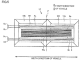
- FIG. 5 is a cross sectional view taken along a V-V line in FIG. 4 .
- iron core 10 includes a main leg 10a and side legs 10b and 10c. Side legs 10b and 10c are connected to main leg 10a. Main leg 10a and side leg 10b form a window W1 in iron core 10. Similarly, main leg 10a and side leg 10c form a window W2 in iron core 10.
- Primary winding 3 and secondary windings 4a and 4b are wound in common around main leg 10a, and passed through windows W1 and W2.
- the Z direction shows the direction of the axis around which primary winding 3 and secondary windings 4a and 4b are wound.
- Secondary winding 4a is disposed above primary winding 3 while secondary winding 4b is disposed below primary winding 3.
- Each of primary winding 3 and secondary windings 4a and 4b includes, for example, a planar coil 4c formed of a coil conductor (for example, made of aluminum) wound on the same plane.
- FIG. 5 shows a cross section of iron core 10 in the direction that is parallel to the direction of the axis around which primary winding 3 and secondary windings 4a and 4b are wound and vertical to the direction passing through windows W1 and W2.
- iron core 10 surrounds primary winding 3 and secondary windings 4a and 4b.
- the transformer according to the present embodiment is the so-called shell-type transformer.
- a tank By employing a shell-type transformer as a transformer for a railroad vehicle, a tank can be formed so as to fit into the shape of each of the iron core and the winding. This allows the volume of the tank to be decreased. The decreased volume of the tank allows further reduction in size of the transformer. Furthermore, since the volume of the tank can be decreased, the amount of the insulation oil within the tank can be reduced. Consequently, the weight of the transformer can be further reduced.
- planar coil 4c the direction of the axis around which planar coil 4c is wound (Z direction) corresponds to the direction of the height of the vehicle.
- primary winding 3 or secondary windings 4a and 4b can be increased in the number of turns without significantly increasing the length of the winding in the height direction of the vehicle.
- Each of secondary windings 4a and 4b has two terminals.
- Secondary winding 4a has terminals 9c and 9d while secondary winding 4b has terminals 9a and 9b.
- Terminals 9a to 9d each correspond to terminal 9 shown in FIG. 1 .
- Terminals 9a to 9d are provided on the outside of iron core 10.
- the plurality of secondary windings each have two terminals that are electrically insulated from another two terminals.
- the terminal connected in common to the plurality of secondary windings is not employed.
- the embodiment of the present invention allows reduction in size of the transformer.
- an explanation will be made based on the comparison between the voltage transforming apparatus according to the first embodiment and its comparative example.
- FIG. 6 is a circuit diagram showing the configuration of a railroad vehicle equipped with a transformer according to a comparative example of the first embodiment of the present invention.
- railroad vehicle 200 is an AC electric train that runs through a plurality of sections in which AC voltages are different.
- Railroad vehicle 200 includes a pantograph 2, a voltage transforming apparatus 100 and a motor 7.
- Voltage transforming apparatus 100 includes a transformer 50, a converter 5, an inverter 6, and a switching circuit 8.
- Transformer 50 includes primary winding 3, secondary windings 4a and 4b, and iron core 10.
- Pantograph 2 is connected to an overhead wire 1.
- Primary winding 3 has the first terminal connected to pantograph 2 and the second terminal provided on the side opposite to the first terminal and connected to the ground node to which a ground voltage is supplied.
- Secondary winding 4a is magnetically coupled to primary winding 3, and has terminal 9a provided at one end of secondary winding 4a and terminal 9b provided at the other end of secondary winding 4a.
- Secondary winding 4b is magnetically coupled to primary winding 3, and has terminal 9b provided at one end of secondary winding 4b and terminal 9c provided at the other end of secondary winding 4b.
- terminal 9b is shared by secondary windings 4a and 4b. It is to be noted that secondary windings 4a and 4b are different in number of turns.
- Switching circuit 8 selectively connects secondary windings 4a and 4b to converter 5.
- switching circuit 8 switches between connection of terminals 9a and 9b of secondary winding 4a to the first input terminal and the second input terminal, respectively, of converter 5 and connection of terminals 9b and 9c of secondary winding 4b to the first input terminal and the second input terminal, respectively, of converter 5.
- the single-phase AC voltage supplied from overhead wire 1 is supplied through pantograph 2 to primary winding 3.
- the AC voltage supplied to primary winding 3 induces an AC voltage in each of secondary windings 4a and 4b.
- Converter 5 converts, into a direct-current (DC) voltage, the AC voltage induced in secondary winding 4a or secondary winding 4b connected to converter 5 by switching circuit 8.
- DC direct-current
- Inverter 6 converts the DC voltage supplied from converter 5 into a three-phase AC voltage, and outputs the voltage to motor 7. Motor 7 is then driven by the three-phase AC voltage supplied from inverter 6.
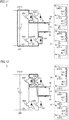
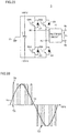
- FIG. 7 is a circuit diagram of the converter shown in FIG. 6.
- FIG. 7 representatively shows the state where terminals 9a and 9b of secondary winding 4a are connected to converter 5.
- converter 5 includes a rectifier circuit 11, switch elements SW1 to SW4, diodes D1 to D4, and a capacitor C.
- Switch elements SW1 to SW4 are connected between the ground node and switching circuit 8.
- the first and second terminals of each of secondary windings 4a and 4b are connected to the ground node through switching circuit 8 and switch elements SW1 to SW4.
- each of switch elements SW1 to SW4 is, for example, a semiconductor switch element such as a thyristor and an IGBT (Insulated Gate Bipolar Transistor).
- Switch element SW1 has one end connected to the first end of capacitor C, the other end connected to a node N1, and a gate.
- Switch element SW2 has one end connected to node N1, the other end connected to the second end of capacitor C, and a gate.
- Switch element SW3 has one end connected to the first end of capacitor C, the other end connected to a node N2, and a gate.
- Switch element SW4 has one end connected to node N2, the other end connected to the second end of capacitor C, and a gate.
- Diode D1 has a cathode connected to one end of switch element SW1 and an anode connected to the other end (node N1) of switch element SW1.
- Diode D2 has a cathode connected to one end (node N1) of switch element SW2 and an anode connected to the other end of switch element SW2.
- Diode D3 has a cathode connected to one end of switch element SW3 and an anode connected to the other end (node N2) of switch element SW3.
- Diode D4 has a cathode connected to one end (node N2) of switch element SW4 and an anode connected to the other end of switch element SW4.
- Converter 5 is a single-ended ground type converter in which capacitor C has one end, for example, the second end, connected to the ground node.
- Rectifier circuit 11 is connected to nodes N1 and N2. Rectifier circuit 11 rectifies the AC voltage induced in secondary winding 4a or secondary winding 4b.
- Switch elements SW1 to SW4 turn on/off based on the control signal received at each gate, to thereby convert the voltage rectified by rectifier circuit 11 into a DC voltage.
- Capacitor C smoothes the DC voltage converted by switch elements SW1 to SW4.
- FIG. 8 is a diagram showing a voltage between the terminals in the secondary winding for each type of the primary voltage. Referring to FIGs. 6 and 8 , when the effective value of the primary voltage, that is, the AC voltage received by primary winding 3, is 25000 V, secondary winding 4b is connected to converter 5 by switching circuit 8 in voltage transforming apparatus 100.
- an AC voltage having an effective value of 1500 V is induced between terminals 9b and 9c.
- the voltage between terminals 9b and 9c (zero peak value) is 2121 V ( FIG. 8(a) ).
- a voltage in accordance with the turns ratio between primary winding 3 and secondary winding 4a is generated.
- an AC voltage having an effective value of 4000 V is induced between terminals 9a and 9c.
- the voltage between terminals 9a and 9c (zero peak value) is 5657 V ( FIG. 8(b) ).
- an AC voltage having an effective value of 1500 V is induced between terminals 9a and 9b.
- the voltage between terminals 9a and 9b (zero peak value) is 2121 V ( FIG. 8(c) ).
- a voltage in accordance with the turns ratio between primary winding 3 and secondary winding 4b is generated.
- an AC voltage having an effective value of 2400 V is induced between terminals 9a and 9c.
- the voltage between terminals 9a and 9c (zero peak value) is 3394 V ( FIG. 8(d) ).
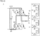
- FIG. 9 is a waveform diagram for illustrating the operation of the converter shown in FIG. 7 .
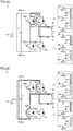
- FIGs. 10 to 13 each are a diagram showing a voltage generated in the low-voltage side winding (secondary winding) and a current generated in the converter at each timing shown in FIG. 9 . Also, FIGs. 10 to 13 each show the voltage and the current that are generated in transformer 51 described later.
- a voltage Vc shows a voltage between terminals 9a and 9b.
- FIG. 9 also shows a voltage pulse waveform obtained by switching (ON/OFF) of switch elements SW1 to SW4.
- Converter 5 has the first input terminal and the second input terminal connected through switching circuit 8 to the first terminal and the second terminals, respectively, of each of secondary windings 4a and 4b. Converter 5 operates so as to alternately connect the first input terminal and the second input terminal to the fixed potential node through switch elements SW1 to SW4.
- switch element SW1 turns off
- switch element SW2 turns on
- switch element SW3 turns off
- switch element SW4 turns off. This causes the current to flow through converter 5 as shown by an arrow in FIG. 10 , in which case the voltage at each of terminals 9a and 9b is 0 V. At this time, the voltage at terminal 9c is also 0 V.
- switch element SW1 turns off
- switch element SW2 turns off
- switch element SW3 turns off
- switch element SW4 turns off.
- switch element SW1 turns off
- switch element SW2 turns off
- switch element SW3 turns on
- switch element SW4 turns off. This causes the current to flow through converter 5 as shown by an arrow in FIG. 12 , in which case the voltage at terminal 9a is 2121 V while the voltage at terminal 9b is 2121 V. At this time, the voltage at terminal 9c is also 2121 V.
- switch element SW1 turns off, switch element SW2 turns on, switch element SW3 turns on, and switch element SW4 turns off.
- the voltage at terminal 9c is -3536 V.
- a voltage of up to 5657 V is generated at the terminal of the secondary winding that is not used (see FIG. 11 ). Accordingly, it becomes necessary to increase an insulation size such as a distance between the winding and the iron core.
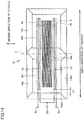
- FIG. 14 is a schematic cross sectional view of the iron core, the primary winding and the secondary winding of transformer 50.
- FIG. 14 is a diagram compared with FIG. 4 .
- the potential of iron core 10 is 0 (V).
- Secondary winding 4a is disposed above primary winding 3 while secondary winding 4b is disposed below primary winding 3.
- the voltage applied to primary winding 3 is higher than the voltage induced in secondary windings 4a and 4b.
- the secondary winding is disposed between primary winding 3 and iron core 10, thereby allowing a gradual change in the voltage in the direction of the axis around which the windings are wound (Z direction). Furthermore, the distance between primary winding 3 and iron core 10 is greater than the distance between secondary winding (4a, 4b) and iron core 10 in the horizontal direction with respect to the iron core. Consequently, the insulation distance between primary winding 3 and iron core 10 is ensured.
- the secondary winding When the number of turns of the secondary winding is decreased, the secondary winding is reduced in size. Accordingly, the insulation distance between iron core 10 and the secondary winding (4a, 4b) can be increased.
- a voltage transforming apparatus 101 in a voltage transforming apparatus 101 according to the embodiment of the present invention, the above-described problems are solved by the structure of the secondary winding.
- the same or equivalent components of voltage transforming apparatus 101 that correspond to those of voltage transforming apparatus 100 are designated by the same reference characters, and description thereof will not be repeated.
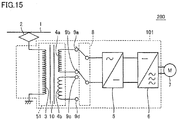
- FIG. 15 is a diagram showing the configuration of the railroad vehicle according to the first embodiment of the present invention.
- railroad vehicle 200 is an AC electric train that runs through a plurality of sections in which AC voltages are different.
- Rail vehicle 200 includes pantograph 2, voltage transforming apparatus 101 and motor 7.
- Voltage transforming apparatus 101 includes transformer 51, converter 5, inverter 6, and switching circuit 8.
- Transformer 51 includes primary winding 3, secondary windings 4a and 4b, and iron core 10.
- Each of secondary windings 4a and 4b has separate first and second terminals at which potentials are not fixed. More specifically, secondary winding 4a is magnetically coupled to primary winding 3, and has terminal 9a provided at one end of secondary winding 4a and terminal 9b provided at the other end of secondary winding 4a.
- Secondary winding 4b is magnetically coupled to primary winding 3, and has terminal 9c provided at one end of secondary winding 4b and terminal 9d provided at the other end of secondary winding 4b. Secondary windings 4a and 4b are different in number of turns.
- Switching circuit 8 selectively connects secondary windings 4a and 4b to converter 5.
- switching circuit 8 selectively connects the first and second terminals of each of secondary windings 4a and 4b to converter 5. More specifically, switching circuit 8 switches between connection of terminals 9a and 9b of secondary winding 4a to the first input terminal and the second input terminal, respectively, of converter 5, and connection of terminals 9c and 9d of secondary winding 4b to the first input terminal and the second input terminal, respectively, of converter 5.
- FIG. 16 is a diagram showing the voltage between the terminals of the secondary winding for each type of the primary voltage. Referring to FIGs. 15 and 16 , when the effective value of the primary voltage, that is, the AC voltage received by primary winding 3, is 25000 V, secondary winding 4b is connected to converter 5 by switching circuit 8 in voltage transforming apparatus 101.
- an AC voltage having an effective value of 1500 V is induced between terminals 9c and 9d.
- the voltage between terminals 9c and 9d (zero peak value) is 2121 V ( FIG. 16(a) ).
- an AC voltage having an effective value of 1500 V is induced between terminals 9a and 9b.
- the voltage between terminals 9a and 9b (zero peak value) is 2121 V ( FIG. 16(c) ).
- switch element SW1 turns off
- switch element SW2 turns on
- switch element SW3 turns off
- switch element SW4 turns off. This causes the current to flow through converter 5 as shown by an arrow in FIG. 10 , in which case the voltage at each of terminals 9a and 9b is 0 V. At this time, the voltage at terminal 9c is also 0 V.
- switch element SW1 turns off
- switch element SW2 turns off
- switch element SW3 turns off
- switch element SW4 turns off. This causes the current to flow through converter 5 as shown by an arrow in FIG. 11 , in which case the voltage at terminal 9a is 0 V while the voltage at terminal 9b is 2121 V.
- a voltage having a magnitude of 5657 V is generated at unused terminal 9c.
- a voltage having a magnitude of 3536 V is generated at unused terminal 9d.
- switch element SW1 turns off
- switch element SW2 turns off
- switch element SW3 turns on
- switch element SW4 turns off. This causes the current to flow as shown by an arrow in FIG. 12 , in which case the voltage at terminal 9a is 2121 V while the voltage at terminal 9b is 2121 V. At this time, the voltage at terminal 9c is 3536 V while the voltage at terminal 9d is 3536 V.
- switch element SW1 turns off, switch element SW2 turns on, switch element SW3 turns on, and switch element SW4 turns off.
- the voltage at terminal 9c is 3536 V while the voltage at terminal 9d is 0 V.
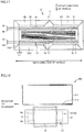
- FIG. 17 is a diagram for illustrating the insulation distance between the iron core and the secondary winding in the case of transformer 51 according to the first embodiment of the present invention.
- FIG. 18 is a diagram for illustrating the insulation distance between the tank and the secondary winding in the case of transformer 51 according to the first embodiment of the present invention.
- the voltage generated at terminal 9d is 3536 V at the maximum. Accordingly, the insulation distance between the secondary winding and iron core 10 can be defined shorter than the insulation distance in the case of transformer 50. In other words, lengths L1 and L2 can be shortened as compared with the case of transformer 50. Therefore, the space within iron core 10 (windows W1 and W2) can be reduced, so that iron core 10 can also be reduced in size.
- tank 21 is also 0 V as with the potential of the iron core.
- the size of tank 21 depends on the insulation distance from secondary windings 4a and 4b to tank 21. As described above, in the first embodiment of the present invention, the voltage generated at unused terminal 9d can be decreased,
- the insulation distance between tank 21 and the secondary winding can also be shortened. This allows a decrease in size of the tank, so that the transformer can be reduced in size and weight.
- each of secondary windings 4a and 4b is not fixed in voltage transforming apparatus 100 and voltage transforming apparatus 101.
- This configuration is specific to the transformer mounted in the AC electric train.
- the secondary winding has one terminal connected to the ground potential.
- FIG. 19 is a circuit diagram showing the configuration of a general AC power supply.
- FIG. 19 representatively shows terminals 9a and 9b of secondary winding 4a.
- the transformer included in an AC power supply 61 employs a single-ended ground system.
- terminal 9b is connected to the ground potential.
- terminal 9b of secondary winding 4a and terminal 9d of secondary winding 4b are connected to the ground potential.
- AC power supply 61 The operation of AC power supply 61 will then be described. In this case, the explanation will be made assuming that, in the transformer of AC power supply 61, the number of turns of primary winding 3 is 1000 T, the number of turns of secondary winding 4a is 100 T, and the number of turns of secondary winding 4b is 60 T.
- FIG. 20 is a waveform diagram showing the operation of the AC power supply shown in FIG. 19 .
- FIGs. 21 to 24 each are a diagram showing the voltage generated in the secondary winding at each timing shown in FIG. 20 .
- voltage Vc shows a voltage between terminals 9a and 9b.
- each voltage at terminals 9a, 9b and 9c is 0 V in transformer 50.
- each voltage at terminals 9a, 9b, 9c, and 9d is 0 V.
- voltages at terminals 9a, 9b and 9c are -2121 V, 0 V and 3536 V, respectively, in transformer 50.
- voltages at terminals 9a, 9b, 9c, and 9d are -2121 V, 0 V, 3536 V, and 0 V, respectively.
- each voltage at terminals 9a, 9b and 9c is 0 V in transformer 50.
- each voltage at terminals 9a, 9b, 9c, and 9d is 0 V.
- voltages at terminals 9a, 9b and 9c are 2121 V, 0 V and -3536 V, respectively, in transformer 50. Furthermore, in transformer 51, voltages at terminals 9a, 9b, 9c, and 9d are 2121 V, 0 V, -3536 V, and 0 V, respectively.
- the terminal provided in one secondary winding is independent of (electrically insulated from) the terminal provided in another secondary winding. Consequently, also in the case where the primary side voltage changes due to vehicle running through several sections of different voltages, the secondary winding side can be optimally designed such that an inductance value (L value), a capacitance value (C value) and a resistance value (R value) required for the voltage transforming apparatus can always be ensured.
- L value inductance value
- C value capacitance value
- R value resistance value
- Stabilized control of the railroad vehicle can be achieved by ensuring the L value, the C value and the R value required for the voltage transforming apparatus. Since the signals of various frequency bands are generally used for the railroad vehicle, consideration should be taken so as to prevent inductive interference from occurring in each type of signal that is caused by high harmonic noise generated from the control devices provided in the vehicle.
- the above-described inductive interference may occur due to the return current flowing through the transformer out of the ground line.
- the inductive interference may cause problems that a malfunction is erroneously detected as occurring in the vehicle (electric train) and the control for stopping the vehicle is performed.
- the L value is particularly important among the above-described L, C, and R values.
- the parameter for determining the L value may include not only one parameter related to the number of turns, but also a plurality of parameters related to the arrangement of the secondary winding (for example, the distance between the primary winding and the secondary winding), and the like.
- transformer 50 When transformer 50 is configured such that the numbers of turns of secondary windings 4a and 4b are set at 40 T and 60 T, respectively, and the potential of terminal 9c is fixed, the induction voltage generated at unused terminal 9a can be lowered during use of terminal 9b.
- a plurality of terminals provided in each of the plurality of secondary windings are independent of another plurality of terminals.
- each secondary winding can be optimized so as to ensure an optimum L value also in the case where the voltage applied to the primary winding changes.
- transformer 51 may include three or more secondary windings.
- voltage transforming apparatus 101 is not limited to that including converter 5 and inverter 6, but only need to include a voltage conversion circuit converting the AC voltage induced in the secondary winding into a desirable voltage.
- converter 5 may be connected not only to the ground node but also to the node to which a fixed voltage is supplied.
- the secondary winding connected to converter 5 is switched by switching circuit 8. This allows a desirable voltage to be extracted by one converter provided in common in a plurality of secondary windings. Therefore, the number of converters can be reduced as compared with the configuration in which a plurality of secondary windings are provided with a plurality of converters, respectively.
- the present embodiment relates to a voltage transforming apparatus provided with a converter that is different in configuration from that of the voltage transforming apparatus according to the first embodiment.
- the voltage transforming apparatus according to the second embodiment is mounted in the AC electric train that runs through a plurality of sections in which AC voltages are different.
- the configuration of the voltage transforming apparatus according to the second embodiment is the same as that shown in each of FIGs. 1 and 4 .
- FIG. 25 is a circuit diagram showing the configuration of the converter according to the second embodiment of the present invention.
- FIG. 25 representatively shows the state where terminals 9a and 9b of secondary winding 4a are connected to converter 5.
- this converter 5 is an intermediate ground type converter in which capacitor C has the first end and the second end each connected to the ground potential.
- the converter according to the second embodiment is different from the converter according to the first embodiment.
- each of voltage transforming apparatus 100 and voltage transforming apparatus 101 is identical to that in the case of the first embodiment of the present invention. Accordingly, in the following description, the operation of each of voltage transforming apparatuses 100 and 101 will be described with reference to FIGs. 8 and 16 , respectively.
- a voltage in accordance with the turns ratio between primary winding 3 and secondary winding 4a is generated.
- an AC voltage having an effective value of 4000 V is induced between terminals 9a and 9c.
- the voltage between terminals 9a and 9c (zero peak value) is 4596 V.
- an AC voltage having an effective value of 1500 V is induced between terminals 9a and 9b.
- the voltage between terminals 9a and 9b (zero peak value) is 1061 V.
- a voltage in accordance with the turns ratio between primary winding 3 and secondary winding 4b is generated.
- an AC voltage having an effective value of 2400 V is induced between terminals 9a and 9c.
- the voltage between terminals 9a and 9c (zero peak value) is 2333 V.
- FIG. 26 is a waveform diagram showing the operation of the converter according to the second embodiment of the present invention.
- FIGs. 27 to 30 each are a diagram showing a voltage generated in the secondary winding and a current generated in the converter at each timing shown in FIG. 26 . It is to be noted that FIGs, 27 to 30 each also show the voltage and the current generated in transformer 51.
- voltage Vc shows a voltage between terminals 9a and 9b.
- FIG. 26 also shows a voltage pulse waveform obtained by switching (ON/OFF) of switch elements SW1 to SW4.
- switch element SW1 turns off
- switch element SW2 turns on
- switch element SW3 turns off
- switch element SW4 turns off. This causes the current to flow through converter 5 as shown by an arrow in FIG. 27 , in which case the voltage at each of terminals 9a and 9b is -1061 V. At this time, the voltage at terminal 9c is also -1061 V.
- switch element SW1 turns off
- switch element SW2 turns off
- switch element SW3 turns off
- switch element SW4 turns off. This causes the current to flow through converter 5 as shown by an arrow in FIG. 28 , in which case the voltage at terminal 9a is -1061 V while the voltage at terminal 9b is 1061 V. At this time, the voltage at terminal 9c is 4596 V.
- switch element SW1 turns off
- switch element SW2 turns off
- switch element SW3 turns on
- switch element SW4 turns off. This causes the current to flow through converter 5 as shown by an arrow in FIG. 29 , in which case the voltage at terminal 9a is 1061 V while the voltage at terminal 9b is 1061 V. At this time, the voltage at terminal 9c is also 1061 V.
- switch element SW1 turns off, switch element SW2 turns on, switch element SW3 turns on, and switch element SW4 turns off.
- the voltage at terminal 9c is -4596 V.
- a voltage of up to 4596 V is generated at the terminal of the secondary winding that is not used.
- this requires an increase in the insulation size such as the distance between the winding and the iron core in the transformer, which makes it difficult to achieve reduction in size and weight of the transformer.
- an AC voltage having an effective value of 1500 V is induced between terminals 9a and 9b.
- the voltage between terminals 9a and 9b (zero peak value) is 1061 V.
- transformer 51 The operation waveform of transformer 51 is the same as that shown in FIG. 26 while the operation of each of switch elements SW1 to SW4 constituting converter 5 is the same as that illustrated in each of FIGs. 27 to 30 .
- an explanation will be representatively made with regard to the operation in the state where terminals 9a and 9b of secondary winding 4a are connected to converter 5.
- switch element SW1 turns off
- switch element SW2 turns on
- switch element SW3 turns off
- switch element SW4 turns off. This causes the current to flow through converter 5 as shown by an arrow in FIG. 27 , in which case the voltage at each of terminals 9a and 9b is -1061 V. At this time, the voltage at each of terminals 9c and 9d is also 0 V.
- switch element SW1 turns off
- switch element SW2 turns off
- switch element SW3 turns off
- switch element SW4 turns off. This causes the current to flow through converter 5 as shown by an arrow in FIG. 28 , in which case the voltage at terminal 9a is -1061 V while the voltage at terminal 9b is 1061 V. At this time, the voltage at terminal 9c is 0 V while the voltage at terminal 9d is 3536 V.
- switch element SW1 turns off
- switch element SW2 turns off
- switch element SW3 turns on
- switch element SW4 turns off. This causes the current to flow through converter 5 as shown by an arrow in FIG. 29 , in which case the voltage at terminal 9a is 1061 V while the voltage at terminal 9b is 1061 V. At this time, the voltage at terminal 9c is 3536 V while the voltage at terminal 9d is 3536 V.
- switch element SW1 turns off, switch element SW2 turns on, switch element SW3 turns on, and switch element SW4 turns off.
- the voltage at terminal 9c is 3536 V while the voltage at terminal 9d is 0 V.
- the transformer can be reduced in size and weight as in the first embodiment. Furthermore, the voltage generated at the terminal of the secondary winding that is not used is decreased, thereby allowing reduction in size and weight of the terminal of the secondary winding.
- each of the above-described embodiments presents a so-called shell-type transformer having a high-voltage winding and a low-voltage winding that are surrounded by an iron core. It is to be noted that the present invention is also applicable to a so-called core-type transformer having a high-voltage winding and a low-voltage winding that are arranged around an iron core.
- the transformer can be reduced in size and weight by applying the present invention to a core-type transformer.
Landscapes
- Engineering & Computer Science (AREA)
- Power Engineering (AREA)
- Life Sciences & Earth Sciences (AREA)
- Sustainable Development (AREA)
- Sustainable Energy (AREA)
- Transportation (AREA)
- Mechanical Engineering (AREA)
- Coils Of Transformers For General Uses (AREA)
- Electric Propulsion And Braking For Vehicles (AREA)
Claims (5)
- Eine Spannungsumwandlungsvorrichtung zur Montage in ein Fahrzeug, das durch eine Vielzahl von Abschnitten, in denen Wechselspannungen unterschiedlich sind, betrieben wird,
wobei die Spannungsumwandlungsvorrichtung dazu geeignet ist, mehrere verschiedene Wechselspannungen umzuwandeln, und Folgendes umfasst:- eine Primärwicklung (3), die eine Wechselspannung erhält;- eine Vielzahl von Sekundärwicklungen (4a, 4b), die sich hinsichtlich der Anzahl der Windungen unterscheiden; und- eine Spannungswandlungsschaltung (5) zur Umwandlung einer in jede Sekundärwicklung aus der Vielzahl der Sekundärwicklungen (4a, 4b) induzierten Wechselspannung in eine erwünschte Spannung,wobei jede Sekundärwicklung aus der Vielzahl von Sekundärwicklungen (4a, 4b) eine erste Klemme und eine zweite Klemme aufweist, von denen jede ein nicht festgelegtes Potential hat, und die erste Klemme und die zweite Klemme separat in jeder der Sekundärwicklungen (4a, 4b) angeordnet sind, wobei die Spannungsumwandlungsvorrichtung darüber hinaus Folgendes umfasst:- einen Schaltkreis (8), um die erste Klemme und die zweite Klemme jeder Sekundärwicklung aus der Vielzahl der Sekundärwicklungen selektiv an die Spannungsumwandlungsschaltung (5) anzuschließen,wobei die Spannungsumwandlungsvorrichtung darüber hinaus einen Eisenkern (10) umfasst, wobei der Eisenkern (10) Folgendes umfasst:- ein Hauptbein (10a), um das die Primärwicklung (3) und die Vielzahl der Sekundärwicklungen (4a, 4b) gewickelt sind, und- ein Seitenbein (10b, 10c), das mit dem Hauptbein (10a) verbunden ist, so dass es die Primärwicklung (3) und die Vielzahl der Sekundärwicklungen (4a, 4b) umschließt,wobei die Vielzahl der Sekundärwicklungen (4a, 4b) eine erste und
eine zweite Sekundärwicklung umfasst, und
wobei die erste und die zweite Sekundärwicklung (4a, 4b) um das Hauptbein (10a) gewickelt sind, so dass sie die Primärwicklung (3) sandwichartig umschließen. - Die Spannungsumwandlungsvorrichtung gemäß Anspruch 1,
welche darüber hinaus einen Behälter (21) umfasst, in dem die Primärwicklung (3), die Vielzahl der Sekundärwicklungen (4a, 4b) und der Eisenkern (10) aufgenommen sind. - Die Spannungsumwandlungsvorrichtung gemäß Anspruch 1 oder 2,
wobei die Primärwicklung (3) und die Vielzahl der Sekundärwicklungen (4a, 4b) jeweils ein auf einer ebenen Fläche gewickelter Leiter sind, wobei die ebene Fläche vertikal zu einer Achse ist, um welche die Wicklungen gewickelt sind. - Die Spannungsumwandlungsvorrichtung gemäß einem der Ansprüche 1 bis 3,
wobei
die Spannungsumwandlungsschaltung (5) ein Schaltelement (SW1 bis SW4) umfasst, das zwischen einem Festpotentialknoten, auf den eine Festspannung aufgebracht wird, und dem Schaltkreis (8) angeschlossen ist, und die erste Klemme und die zweite Klemme jeder Sekundärwicklung aus der Vielzahl von Sekundärwicklungen (4a, 4b) durch den Schaltkreis (8) und das Schaltelement (SW1 bis SW4) an den Festpotentialknoten angeschlossen sind. - Die Spannungsumwandlungsvorrichtung gemäß Anspruch 4,
wobei die Spannungsumwandlungsschaltung (5) eine erste Eingangsklemme und eine zweite Eingangsklemme aufweist, die über den Schaltkreis (8) jeweils an die erste und die zweite Klemme jeder Sekundärwicklung aus der Vielzahl der Sekundärwicklungen (4a, 4b) angeschlossen sind, und die Spannungsumwandlungsvorrichtung so funktioniert, dass ein Potential der ersten Eingangsklemme und ein Potential der zweiten Eingangsklemme durch das Schaltelement (SW1 bis SW4) abwechselnd an den Festpotentialknoten angeschlossen werden.
Applications Claiming Priority (2)
| Application Number | Priority Date | Filing Date | Title |
|---|---|---|---|
| JP2009070394 | 2009-12-04 | ||
| PCT/JP2010/070702 WO2011068044A1 (ja) | 2009-12-04 | 2010-11-19 | 変圧装置 |
Publications (3)
| Publication Number | Publication Date |
|---|---|
| EP2509083A1 EP2509083A1 (de) | 2012-10-10 |
| EP2509083A4 EP2509083A4 (de) | 2015-01-14 |
| EP2509083B1 true EP2509083B1 (de) | 2019-07-10 |
Family
ID=44114893
Family Applications (1)
| Application Number | Title | Priority Date | Filing Date |
|---|---|---|---|
| EP10834496.1A Active EP2509083B1 (de) | 2009-12-04 | 2010-11-19 | Spannungstransformator |
Country Status (3)
| Country | Link |
|---|---|
| US (1) | US8648684B2 (de) |
| EP (1) | EP2509083B1 (de) |
| WO (1) | WO2011068044A1 (de) |
Families Citing this family (7)
| Publication number | Priority date | Publication date | Assignee | Title |
|---|---|---|---|---|
| KR101149955B1 (ko) * | 2008-03-04 | 2012-05-31 | 미쓰비시덴키 가부시키가이샤 | 변압 장치 |
| CN104937680B (zh) * | 2012-10-19 | 2017-04-26 | 三菱电机株式会社 | 逆变器装置、变压器及变压器的制造方法 |
| WO2015107691A1 (ja) * | 2014-01-20 | 2015-07-23 | 三菱電機株式会社 | 車載変圧器 |
| DE102014213073A1 (de) * | 2014-07-04 | 2016-01-07 | Siemens Aktiengesellschaft | Hochspannungseinrichtung für ein Fahrzeug |
| WO2016103439A1 (ja) * | 2014-12-26 | 2016-06-30 | 三菱電機株式会社 | 車両用変圧器 |
| CN109935455A (zh) * | 2019-04-30 | 2019-06-25 | 江苏华鹏变压器有限公司 | 一种110kV三相干式变压器 |
| CN111786360A (zh) * | 2020-06-29 | 2020-10-16 | 神华包神铁路集团有限责任公司 | 适配器电路 |
Family Cites Families (21)
| Publication number | Priority date | Publication date | Assignee | Title |
|---|---|---|---|---|
| JPS5145257A (ja) * | 1974-10-16 | 1976-04-17 | Fuji Electric Co Ltd | Tansokoryuseiryukishikisharyono denatsuseigyohoho |
| JPH0713927B2 (ja) | 1987-02-25 | 1995-02-15 | 株式会社東芝 | タツプ切換装置付巻線 |
| DE3817652A1 (de) * | 1988-05-25 | 1989-12-07 | Asea Brown Boveri | Elektrisch betriebenes schienentriebfahrzeug mit mindestens zwei antriebsanlagen |
| JP2680385B2 (ja) | 1988-12-05 | 1997-11-19 | 株式会社東芝 | 電気車用補助電源装置 |
| JPH02184007A (ja) | 1989-01-10 | 1990-07-18 | Mitsubishi Electric Corp | 車両用変圧器 |
| JPH02307303A (ja) * | 1989-05-22 | 1990-12-20 | Fuji Electric Co Ltd | 交流電車の駆動方式 |
| JPH04148012A (ja) | 1990-10-09 | 1992-05-21 | Nissan Motor Co Ltd | エンジンの排気還流装置 |
| KR970000106B1 (ko) | 1992-01-17 | 1997-01-04 | 미쯔비시 덴끼 가부시기가이샤 | 차량탑재용 변압기 |
| JP3416809B2 (ja) | 1994-05-27 | 2003-06-16 | 成勲 井本 | 電気調整器 |
| US6075717A (en) * | 1996-05-01 | 2000-06-13 | General Electric Company | PWM rectifier control with switching losses equally distributed among multiple switching devices |
| DE19702132C1 (de) * | 1997-01-22 | 1998-07-23 | Siemens Ag | Einspeiseschaltung für ein Bordnetz eines Mehrsystemfahrzeugs |
| ATE478465T1 (de) * | 2001-02-05 | 2010-09-15 | Faiveley Transport | Energiewandler |
| JP4232504B2 (ja) | 2003-03-27 | 2009-03-04 | 株式会社明電舎 | 交流電圧調整装置 |
| DE102004033994B4 (de) * | 2003-07-16 | 2017-07-27 | Denso Corporation | Gleichstrom-Gleichstrom-Wandler |
| JP2006204036A (ja) | 2005-01-21 | 2006-08-03 | Mitsubishi Electric Corp | 車両用電力変換装置 |
| US8049455B2 (en) * | 2006-10-19 | 2011-11-01 | Mitsubishi Electric Corporation | Electric power converter |
| JP4546439B2 (ja) * | 2006-10-31 | 2010-09-15 | 株式会社デンソー | 2トランス型dcdcコンバータの磁気回路 |
| JP2009182115A (ja) * | 2008-01-30 | 2009-08-13 | Mitsubishi Electric Corp | 変圧器 |
| KR101149955B1 (ko) | 2008-03-04 | 2012-05-31 | 미쓰비시덴키 가부시키가이샤 | 변압 장치 |
| WO2010092676A1 (ja) | 2009-02-13 | 2010-08-19 | 三菱電機株式会社 | 変圧器 |
| CA2843730C (en) | 2009-03-13 | 2015-06-30 | Kabushiki Kaisha Toshiba | Rolling stock system and control method thereof |
-
2010
- 2010-11-19 US US13/392,478 patent/US8648684B2/en not_active Expired - Fee Related
- 2010-11-19 WO PCT/JP2010/070702 patent/WO2011068044A1/ja not_active Ceased
- 2010-11-19 EP EP10834496.1A patent/EP2509083B1/de active Active
Non-Patent Citations (1)
| Title |
|---|
| None * |
Also Published As
| Publication number | Publication date |
|---|---|
| WO2011068044A1 (ja) | 2011-06-09 |
| US8648684B2 (en) | 2014-02-11 |
| EP2509083A4 (de) | 2015-01-14 |
| EP2509083A1 (de) | 2012-10-10 |
| US20120154090A1 (en) | 2012-06-21 |
Similar Documents
| Publication | Publication Date | Title |
|---|---|---|
| EP2509083B1 (de) | Spannungstransformator | |
| CN110896277B (zh) | 车辆电源装置 | |
| EP2192678B1 (de) | Nutzung eines Magnetkerns in einem Stromrichter für ein elektrisches Fahrzeug | |
| US7447050B2 (en) | Multilevel converter and method of converting a supply voltage | |
| US8421571B2 (en) | Transformer | |
| KR102349935B1 (ko) | 반도체 변압기 전원공급장치 및 그의 동작 방법 | |
| CN101960542B (zh) | 变压装置 | |
| US5546295A (en) | Electrical power converter, power supply, and inverter with series-connected switching circuits | |
| JP5159984B1 (ja) | 変圧器およびそれを含む変圧装置 | |
| KR101953571B1 (ko) | 무선 전력 전송 코일을 구비한 차량용 반도체 변압기 및 그 무선 전력 전송 코일 | |
| JP2009182115A (ja) | 変圧器 | |
| CN111937286A (zh) | Llc谐振转换器 | |
| JP4750903B2 (ja) | 変圧装置 | |
| US20150102678A1 (en) | Parallel Inverters Connected to One Inductor | |
| US9406431B2 (en) | Transformer and voltage transforming apparatus comprising the same | |
| KR102464779B1 (ko) | 반도체 변압기의 무선 급집전 코일 구조 | |
| CN1419251A (zh) | 多系统驱动车的变压器和馈送电路 | |
| TWI416554B (zh) | 變壓裝置 | |
| EP4261856A1 (de) | Transformator für fahrzeuge und fahrzeug damit | |
| KR102589807B1 (ko) | 보조권선을 구비한 변압기 | |
| JP2006204036A (ja) | 車両用電力変換装置 | |
| WO2013179475A1 (ja) | 変圧装置 | |
| HK1145232A (en) | Power converting device for electric vehicle | |
| HK1151385B (en) | Electric transformer |
Legal Events
| Date | Code | Title | Description |
|---|---|---|---|
| PUAI | Public reference made under article 153(3) epc to a published international application that has entered the european phase |
Free format text: ORIGINAL CODE: 0009012 |
|
| 17P | Request for examination filed |
Effective date: 20120530 |
|
| AK | Designated contracting states |
Kind code of ref document: A1 Designated state(s): AL AT BE BG CH CY CZ DE DK EE ES FI FR GB GR HR HU IE IS IT LI LT LU LV MC MK MT NL NO PL PT RO RS SE SI SK SM TR |
|
| DAX | Request for extension of the european patent (deleted) | ||
| A4 | Supplementary search report drawn up and despatched |
Effective date: 20141212 |
|
| RIC1 | Information provided on ipc code assigned before grant |
Ipc: G05F 1/14 20060101ALI20141208BHEP Ipc: B60L 9/16 20060101ALI20141208BHEP Ipc: H01F 29/02 20060101AFI20141208BHEP Ipc: B60L 9/28 20060101ALI20141208BHEP |
|
| STAA | Information on the status of an ep patent application or granted ep patent |
Free format text: STATUS: EXAMINATION IS IN PROGRESS |
|
| 17Q | First examination report despatched |
Effective date: 20170301 |
|
| GRAP | Despatch of communication of intention to grant a patent |
Free format text: ORIGINAL CODE: EPIDOSNIGR1 |
|
| STAA | Information on the status of an ep patent application or granted ep patent |
Free format text: STATUS: GRANT OF PATENT IS INTENDED |
|
| INTG | Intention to grant announced |
Effective date: 20190121 |
|
| GRAS | Grant fee paid |
Free format text: ORIGINAL CODE: EPIDOSNIGR3 |
|
| GRAA | (expected) grant |
Free format text: ORIGINAL CODE: 0009210 |
|
| STAA | Information on the status of an ep patent application or granted ep patent |
Free format text: STATUS: THE PATENT HAS BEEN GRANTED |
|
| AK | Designated contracting states |
Kind code of ref document: B1 Designated state(s): AL AT BE BG CH CY CZ DE DK EE ES FI FR GB GR HR HU IE IS IT LI LT LU LV MC MK MT NL NO PL PT RO RS SE SI SK SM TR |
|
| REG | Reference to a national code |
Ref country code: GB Ref legal event code: FG4D |
|
| REG | Reference to a national code |
Ref country code: CH Ref legal event code: EP Ref country code: AT Ref legal event code: REF Ref document number: 1154417 Country of ref document: AT Kind code of ref document: T Effective date: 20190715 |
|
| REG | Reference to a national code |
Ref country code: DE Ref legal event code: R096 Ref document number: 602010059990 Country of ref document: DE |
|
| REG | Reference to a national code |
Ref country code: IE Ref legal event code: FG4D |
|
| REG | Reference to a national code |
Ref country code: NL Ref legal event code: MP Effective date: 20190710 |
|
| REG | Reference to a national code |
Ref country code: LT Ref legal event code: MG4D |
|
| REG | Reference to a national code |
Ref country code: AT Ref legal event code: MK05 Ref document number: 1154417 Country of ref document: AT Kind code of ref document: T Effective date: 20190710 |
|
| PG25 | Lapsed in a contracting state [announced via postgrant information from national office to epo] |
Ref country code: SE Free format text: LAPSE BECAUSE OF FAILURE TO SUBMIT A TRANSLATION OF THE DESCRIPTION OR TO PAY THE FEE WITHIN THE PRESCRIBED TIME-LIMIT Effective date: 20190710 Ref country code: NL Free format text: LAPSE BECAUSE OF FAILURE TO SUBMIT A TRANSLATION OF THE DESCRIPTION OR TO PAY THE FEE WITHIN THE PRESCRIBED TIME-LIMIT Effective date: 20190710 Ref country code: BG Free format text: LAPSE BECAUSE OF FAILURE TO SUBMIT A TRANSLATION OF THE DESCRIPTION OR TO PAY THE FEE WITHIN THE PRESCRIBED TIME-LIMIT Effective date: 20191010 Ref country code: AT Free format text: LAPSE BECAUSE OF FAILURE TO SUBMIT A TRANSLATION OF THE DESCRIPTION OR TO PAY THE FEE WITHIN THE PRESCRIBED TIME-LIMIT Effective date: 20190710 Ref country code: NO Free format text: LAPSE BECAUSE OF FAILURE TO SUBMIT A TRANSLATION OF THE DESCRIPTION OR TO PAY THE FEE WITHIN THE PRESCRIBED TIME-LIMIT Effective date: 20191010 Ref country code: FI Free format text: LAPSE BECAUSE OF FAILURE TO SUBMIT A TRANSLATION OF THE DESCRIPTION OR TO PAY THE FEE WITHIN THE PRESCRIBED TIME-LIMIT Effective date: 20190710 Ref country code: HR Free format text: LAPSE BECAUSE OF FAILURE TO SUBMIT A TRANSLATION OF THE DESCRIPTION OR TO PAY THE FEE WITHIN THE PRESCRIBED TIME-LIMIT Effective date: 20190710 Ref country code: PT Free format text: LAPSE BECAUSE OF FAILURE TO SUBMIT A TRANSLATION OF THE DESCRIPTION OR TO PAY THE FEE WITHIN THE PRESCRIBED TIME-LIMIT Effective date: 20191111 Ref country code: LT Free format text: LAPSE BECAUSE OF FAILURE TO SUBMIT A TRANSLATION OF THE DESCRIPTION OR TO PAY THE FEE WITHIN THE PRESCRIBED TIME-LIMIT Effective date: 20190710 |
|
| PG25 | Lapsed in a contracting state [announced via postgrant information from national office to epo] |
Ref country code: AL Free format text: LAPSE BECAUSE OF FAILURE TO SUBMIT A TRANSLATION OF THE DESCRIPTION OR TO PAY THE FEE WITHIN THE PRESCRIBED TIME-LIMIT Effective date: 20190710 Ref country code: ES Free format text: LAPSE BECAUSE OF FAILURE TO SUBMIT A TRANSLATION OF THE DESCRIPTION OR TO PAY THE FEE WITHIN THE PRESCRIBED TIME-LIMIT Effective date: 20190710 Ref country code: GR Free format text: LAPSE BECAUSE OF FAILURE TO SUBMIT A TRANSLATION OF THE DESCRIPTION OR TO PAY THE FEE WITHIN THE PRESCRIBED TIME-LIMIT Effective date: 20191011 Ref country code: IS Free format text: LAPSE BECAUSE OF FAILURE TO SUBMIT A TRANSLATION OF THE DESCRIPTION OR TO PAY THE FEE WITHIN THE PRESCRIBED TIME-LIMIT Effective date: 20191110 Ref country code: RS Free format text: LAPSE BECAUSE OF FAILURE TO SUBMIT A TRANSLATION OF THE DESCRIPTION OR TO PAY THE FEE WITHIN THE PRESCRIBED TIME-LIMIT Effective date: 20190710 Ref country code: LV Free format text: LAPSE BECAUSE OF FAILURE TO SUBMIT A TRANSLATION OF THE DESCRIPTION OR TO PAY THE FEE WITHIN THE PRESCRIBED TIME-LIMIT Effective date: 20190710 |
|
| PG25 | Lapsed in a contracting state [announced via postgrant information from national office to epo] |
Ref country code: TR Free format text: LAPSE BECAUSE OF FAILURE TO SUBMIT A TRANSLATION OF THE DESCRIPTION OR TO PAY THE FEE WITHIN THE PRESCRIBED TIME-LIMIT Effective date: 20190710 |
|
| PG25 | Lapsed in a contracting state [announced via postgrant information from national office to epo] |
Ref country code: PL Free format text: LAPSE BECAUSE OF FAILURE TO SUBMIT A TRANSLATION OF THE DESCRIPTION OR TO PAY THE FEE WITHIN THE PRESCRIBED TIME-LIMIT Effective date: 20190710 Ref country code: EE Free format text: LAPSE BECAUSE OF FAILURE TO SUBMIT A TRANSLATION OF THE DESCRIPTION OR TO PAY THE FEE WITHIN THE PRESCRIBED TIME-LIMIT Effective date: 20190710 Ref country code: DK Free format text: LAPSE BECAUSE OF FAILURE TO SUBMIT A TRANSLATION OF THE DESCRIPTION OR TO PAY THE FEE WITHIN THE PRESCRIBED TIME-LIMIT Effective date: 20190710 Ref country code: RO Free format text: LAPSE BECAUSE OF FAILURE TO SUBMIT A TRANSLATION OF THE DESCRIPTION OR TO PAY THE FEE WITHIN THE PRESCRIBED TIME-LIMIT Effective date: 20190710 Ref country code: IT Free format text: LAPSE BECAUSE OF FAILURE TO SUBMIT A TRANSLATION OF THE DESCRIPTION OR TO PAY THE FEE WITHIN THE PRESCRIBED TIME-LIMIT Effective date: 20190710 |
|
| PG25 | Lapsed in a contracting state [announced via postgrant information from national office to epo] |
Ref country code: CZ Free format text: LAPSE BECAUSE OF FAILURE TO SUBMIT A TRANSLATION OF THE DESCRIPTION OR TO PAY THE FEE WITHIN THE PRESCRIBED TIME-LIMIT Effective date: 20190710 Ref country code: SK Free format text: LAPSE BECAUSE OF FAILURE TO SUBMIT A TRANSLATION OF THE DESCRIPTION OR TO PAY THE FEE WITHIN THE PRESCRIBED TIME-LIMIT Effective date: 20190710 Ref country code: SM Free format text: LAPSE BECAUSE OF FAILURE TO SUBMIT A TRANSLATION OF THE DESCRIPTION OR TO PAY THE FEE WITHIN THE PRESCRIBED TIME-LIMIT Effective date: 20190710 Ref country code: IS Free format text: LAPSE BECAUSE OF FAILURE TO SUBMIT A TRANSLATION OF THE DESCRIPTION OR TO PAY THE FEE WITHIN THE PRESCRIBED TIME-LIMIT Effective date: 20200224 |
|
| REG | Reference to a national code |
Ref country code: DE Ref legal event code: R119 Ref document number: 602010059990 Country of ref document: DE |
|
| PLBE | No opposition filed within time limit |
Free format text: ORIGINAL CODE: 0009261 |
|
| STAA | Information on the status of an ep patent application or granted ep patent |
Free format text: STATUS: NO OPPOSITION FILED WITHIN TIME LIMIT |
|
| PG2D | Information on lapse in contracting state deleted |
Ref country code: IS |
|
| PG25 | Lapsed in a contracting state [announced via postgrant information from national office to epo] |
Ref country code: MC Free format text: LAPSE BECAUSE OF FAILURE TO SUBMIT A TRANSLATION OF THE DESCRIPTION OR TO PAY THE FEE WITHIN THE PRESCRIBED TIME-LIMIT Effective date: 20190710 Ref country code: LU Free format text: LAPSE BECAUSE OF NON-PAYMENT OF DUE FEES Effective date: 20191119 |
|
| 26N | No opposition filed |
Effective date: 20200603 |
|
| REG | Reference to a national code |
Ref country code: BE Ref legal event code: MM Effective date: 20191130 |
|
| PG25 | Lapsed in a contracting state [announced via postgrant information from national office to epo] |
Ref country code: SI Free format text: LAPSE BECAUSE OF FAILURE TO SUBMIT A TRANSLATION OF THE DESCRIPTION OR TO PAY THE FEE WITHIN THE PRESCRIBED TIME-LIMIT Effective date: 20190710 |
|
| GBPC | Gb: european patent ceased through non-payment of renewal fee |
Effective date: 20191119 |
|
| PG25 | Lapsed in a contracting state [announced via postgrant information from national office to epo] |
Ref country code: FR Free format text: LAPSE BECAUSE OF NON-PAYMENT OF DUE FEES Effective date: 20191130 Ref country code: DE Free format text: LAPSE BECAUSE OF NON-PAYMENT OF DUE FEES Effective date: 20200603 Ref country code: IE Free format text: LAPSE BECAUSE OF NON-PAYMENT OF DUE FEES Effective date: 20191119 Ref country code: GB Free format text: LAPSE BECAUSE OF NON-PAYMENT OF DUE FEES Effective date: 20191119 |
|
| PG25 | Lapsed in a contracting state [announced via postgrant information from national office to epo] |
Ref country code: BE Free format text: LAPSE BECAUSE OF NON-PAYMENT OF DUE FEES Effective date: 20191130 |
|
| PG25 | Lapsed in a contracting state [announced via postgrant information from national office to epo] |
Ref country code: CY Free format text: LAPSE BECAUSE OF FAILURE TO SUBMIT A TRANSLATION OF THE DESCRIPTION OR TO PAY THE FEE WITHIN THE PRESCRIBED TIME-LIMIT Effective date: 20190710 |
|
| PG25 | Lapsed in a contracting state [announced via postgrant information from national office to epo] |
Ref country code: MT Free format text: LAPSE BECAUSE OF FAILURE TO SUBMIT A TRANSLATION OF THE DESCRIPTION OR TO PAY THE FEE WITHIN THE PRESCRIBED TIME-LIMIT Effective date: 20190710 Ref country code: HU Free format text: LAPSE BECAUSE OF FAILURE TO SUBMIT A TRANSLATION OF THE DESCRIPTION OR TO PAY THE FEE WITHIN THE PRESCRIBED TIME-LIMIT; INVALID AB INITIO Effective date: 20101119 |
|
| PG25 | Lapsed in a contracting state [announced via postgrant information from national office to epo] |
Ref country code: MK Free format text: LAPSE BECAUSE OF FAILURE TO SUBMIT A TRANSLATION OF THE DESCRIPTION OR TO PAY THE FEE WITHIN THE PRESCRIBED TIME-LIMIT Effective date: 20190710 |
|
| PGFP | Annual fee paid to national office [announced via postgrant information from national office to epo] |
Ref country code: CH Payment date: 20241201 Year of fee payment: 15 |