EP2509152A2 - HF-Filteranordnung sowie Verfahren zur Variation einer elektromagnetischen Koppelstärke zwischen zwei Topfkreis-Resonatoren - Google Patents
HF-Filteranordnung sowie Verfahren zur Variation einer elektromagnetischen Koppelstärke zwischen zwei Topfkreis-Resonatoren Download PDFInfo
- Publication number
- EP2509152A2 EP2509152A2 EP12002363A EP12002363A EP2509152A2 EP 2509152 A2 EP2509152 A2 EP 2509152A2 EP 12002363 A EP12002363 A EP 12002363A EP 12002363 A EP12002363 A EP 12002363A EP 2509152 A2 EP2509152 A2 EP 2509152A2
- Authority
- EP
- European Patent Office
- Prior art keywords
- coupling
- finger
- resonators
- rod element
- plane
- Prior art date
- Legal status (The legal status is an assumption and is not a legal conclusion. Google has not performed a legal analysis and makes no representation as to the accuracy of the status listed.)
- Granted
Links
Images


Classifications
-
- H—ELECTRICITY
- H01—ELECTRIC ELEMENTS
- H01P—WAVEGUIDES; RESONATORS, LINES, OR OTHER DEVICES OF THE WAVEGUIDE TYPE
- H01P1/00—Auxiliary devices
- H01P1/20—Frequency-selective devices, e.g. filters
- H01P1/201—Filters for transverse electromagnetic waves
- H01P1/205—Comb or interdigital filters; Cascaded coaxial cavities
- H01P1/2053—Comb or interdigital filters; Cascaded coaxial cavities the coaxial cavity resonators being disposed parall to each other
Definitions
- the invention relates to an RF filter arrangement having at least two capacitively coupled cup-circle resonators, which are coupled via a common, electrically conductive pot wall or via each electrically interconnected pot walls, wherein in the common pot wall or in the electrically interconnected pot walls, a coupling window is introduced , Which is completely enclosed by electrically conductive material and in which a coupling means with variably adjustable capacity is introduced.
- an RF filter which comprises a plurality of coupled pot resonators, which are arrayed along at least two rows and at least two columns, wherein the coupling between two arranged in the row direction cavity resonators is formed inductively and the coupling of at least two Capacitive adjacent in the column arrangement Topf Vietnamese resonators is capacitive.
- band filter between the transmission amplifier unit and the antenna are arranged to possibly present in the amplifier output noise in the form of on Use frequency range immediately adjacent disturbing side or side lines to suppress.
- This represents a special one technical challenge especially since such interference lines or interference signal components in adjacent channels due to the small frequency spacing to the useful frequency frequency range, which is predetermined by the respective transmission channel and its center frequency and channel bandwidth, should be eliminated or suppressed as possible without relevant impairment of the useful frequency range.
- RF signals in certain frequency bands or areas mandatory standards, so for example.
- digital content such as television, radio, multi-channel audio, compliance with DVB, ATSC etc. standards.
- band filters are used with HF moderately coupled to each other Topf Vietnamese filter, which are arranged so that between two RF moderately non-successive Topf Vietnamese En a transverse or negative feedback is provided ,
- a band filter of Topf Vietnameseen is in the DE 199 16 605 C1 described. Due to the negative feedback of HF-moderately non-consecutive pot circuits, the flanks of the transmission curve become stiffer and thus increase the selectivity of the bandpass filter.
- negative feedback bandpass filter after the DE 199 16 605 C1 are the gegenzukoppelnden pot circuits arranged so that the pot circuits are mechanically adjacent and the negative feedback is formed as a dipping into the one pot loop, which is connected by a formed in the partition between the two adjacent pot circles slot with a punch in the other pot circle ,
- the loop and the punch expediently form a unitary line piece whose depth of immersion into the cup circles and thus the degree of counter-coupling can be varied.
- the loop causes an inductive Coupling, the stamp, however, a capacitive coupling. The transition from the inductive to the capacitive coupling simultaneously causes a necessary phase rotation by 180 °.
- the filter is tuned in a manner known per se to a lower center frequency and the negative feedback of the respective pottraces is to remain constant, then the area of the loop immersed in the one potted circle must be increased for this purpose. This is done by increasing the immersion depth of the pipe section. This also shifts the capacitive coupling causing stamp in the other pot circle.
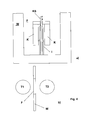
- a band-pass filter with counter-coupled pot circuits T1, T2 is known in which a common wall W of two mechanically adjacent pot circuits T1, T2 has a window F (see Fig. 4b ).
- a bridge-like, formed symmetrically to the window plane capacitive coupling element K is arranged, which is supported on an insulator I, see Fig. 4a .
- the coupling element K has in the symmetry / window plane a bore parallel to the inner conductors of the cup-circle resonators, in which by means of the insulator I electrically isolated a coupling pin KS is axially displaceably mounted.
- the coupling pin pin KS is in a non-inserted position, so the capacitive coupling between the Topf Vietnameseresonatoren T1, T2 is maximum. If the coupling pin KS is inserted into the bore of the insulator I, then this acts as a variable capacitance to ground, ie the effective capacitive coupling between the Topf Vietnameseresonatoren is reduced.
- Out DE 12 22 600 B is a tunable filter assembly of at least two coupled resonant line sections known in which the coupling is varied over a change in the radial extension of two linearly movable pin parts in the resonant line sections transverse to the resonator longitudinal axes.
- the object of the invention is to improve the capacitive cross-coupling between two cavity resonators, especially with regard to the possibilities of variation of the coupling factor and the minimization of existing losses.
- the object of the invention is achieved by an RF filter arrangement according to claim 1, an RF filter according to claims 10 and 11 and by a method for varying an electromagnetic coupling strength according to claim 12.
- the claim 1 relates to an RF filter arrangement with at least two cup-circle resonators, which are coupled via a common, electrically conductive pot wall or electrically interconnected each pot walls, wherein introduced in the common pot wall or in the electrically interconnected pot walls a coupling window is completely enclosed by electrically conductive material and in which a coupling agent with variably adjustable capacity is introduced.
- a solution according to the invention RF filter assembly is characterized in that the coupling means comprises an electrically conductive rod element with a rod axis and two rod element ends, the both sides of the rod element ends with the coupling window enclosing electrically conductive material is electrically conductively connected, and that electrically insulated from the rod element at least two electrically interconnected, made of electrically conductive material finger elements are attached to the rod member, are rotatably mounted about a coincident with the rod axis axis of rotation.
- the coupling window is subdivided into two smaller sub-windows by the electrically conductive and electrically conductive rod element connected to the surrounding material, whereby a parasitic inductive coupling acting through the window surface can be largely suppressed or compensated by this sub-windowing.
- a parasitic inductive coupling acting through the window surface can be largely suppressed or compensated by this sub-windowing.
- the size of the coupling factor can thus be varied within a large range, so that the filter characteristic of a bandpass filter can be used for many different broadcast standards, such as e.g. ATSC, DVB-T, ISDB-T are adjustable.
- the coupling factor between minimum coupling, i. Coupling factor zero, and maximum coupling with in principle a 1 ⁇ 4-rotation of the finger elements are varied around the axis of rotation. With minimal coupling, the finger elements are approximately in a plane assignable to the window. The fingers unfold an additional inductive shield effect by dividing the original window in cooperation with the rod element into four smaller windows.
- the rod member divides the coupling window into two substantially symmetrical window areas, i. the rod element blocks the middle of the original coupling window, whereby very low coupling factors can be realized.
- the RF filter arrangement is characterized in that the rod element is arranged rotatably about the axis of rotation within the coupling window and the at least two finger elements are mounted non-rotatably on the rod element.
- a finger receptacle made of electrically conductive material, on which the finger elements are arranged, is suitable.
- the finger holder has a bore, which is penetrated by the electrically conductive rod element.
- an insulator is inserted, which surrounds the rod member at least partially concentric with respect to. Of the axis of rotation in the region of the finger receiving.
- the gaps between the finger elements and the coupling window need not necessarily be parallel, i.
- the finger elements can be arranged inclined with respect to the axis of rotation in the radial direction, for example.
- bar-shaped finger elements which are arranged parallel and equidistant from the axis of rotation.
- the finger elements are arranged diametrically opposite to the rod element.
- an arrangement which is slightly offset in comparison with the diametrical arrangement is also conceivable, ie an angle formed by the imaginary radial connecting lines between a respective finger element and the rod element does not correspond to 180 °, but differs therefrom, preferably into an angular range of ⁇ ⁇ ⁇ 15 ° from the 180 ° position, ie a first plane defined by a finger element and the Bar element is clamped, a second plane, which is spanned by the rod member and the other finger element, intersects at the angle ⁇ , for which applies ⁇ ⁇ 15 °.
- the gaps between the finger elements and the coupling window need not necessarily be parallel, i.
- the finger elements may be inclined, for example, with respect to the axis of rotation in the radial direction.
- the shape of the rod element, the finger elements and the finger mount can take on any shape.
- the rod element and the finger elements variants with respect to the cross-sectional shape, e.g. round, angular, oval, symmetrical, asymmetrical, hollow or made of solid material, possible, as well as cross-sectional variations in the axial direction, e.g. crowned or waisted, continuous or unsteady cross-sectional changes.
- All elements of the coupling agent, i. Finger elements, rod element, finger receptor are preferably surface treated, i. For example, provided with a particularly conductive surface, such. Silver, copper, gold, etc., to optimize the effect.
- the rod element is aligned parallel to the longitudinal extension of an inner conductor of at least one of the at least two cavity resonators.
- At least partially, preferably completely, comprise the at least two cup-circle resonators of a housing in an electrically conductive manner and to rotatably or indirectly form the bar element from outside the housing with the aid of an actuating means.
- the finger elements are rotatably mounted about the axis of rotation in a rotation angle range of at least 80 °, preferably at least 90 °, particularly preferably of 180 °.
- a locking means is provided for fixing the rotational angle adjustment, whereby the actuating means, with which the angle of rotation of the finger elements is adjusted, can be secured against unintentional adjustment.
- the solution according to the filter arrangement is characterized in an advantageous manner by the structural compactness, especially since the complete coupling means including the operation and the attachment within the minimum installation space of the filter assembly can be integrated.
- the complete coupling means including the operation and the attachment within the minimum installation space of the filter assembly can be integrated.
- no differently far, depending on the degree of coupling, in the vicinity of the filter housing projecting adjusting elements are required, as is the case with the known comparable filter arrangements.
- an actuation of the coupling means of two opposite sides of the filter housing is possible, provided that the actuating means is guided on both sides to the outside, whereas known from the prior art cross-couplings are usually actuated only from a filter housing side.
- capacitive coupling between two Topf Vietnamese resonatoren can also be an RF filter with a plurality of coupled Topf Vietnamese resonators build, which are arrayed along at least two rows and at least two columns, the coupling between two arranged in the row direction Circular resonators is designed inductively.
- the ring-type resonators arranged in rows are RF-coupled.
- For a serial RF-moderate coupling of two parallel lines only two cavity resonators, which face each other at the end of the line along a column, are also coupled HF-moderately.
- the RF filter is characterized in that at least a pair of well resonators arranged in the column direction as an RF filter arrangement is formed according to one of claims 1 to 9, ie in the two in the column direction adjacent to each other via a common wall cavity resonators is a window in which the rod element is provided with the rotatably arranged thereon finger elements to the coupling capacity and thus the coupling strength between to vary continuously in the two arranged in the column direction Topf Vietnamese resonators.
- the solution according to variable adjustable coupling capacitance can also be modified in the use of this RF filter according to the embodiments described above.
- the coupling of the RF signal to be filtered is carried out in the row direction, preferably inductively in a first cavity resonator.
- the Hauptausbreitungspfad extends in the row direction through the lying in the first row Topf Vietnamese resonators 1 to 3, then in the column direction by the coupling of the Topf Vietnamese resonators 3 and 4 and then again in the row direction (but now opposite) by lying in the second row Potnik resonators 4 to 6.
- a filtered RF signal can be coupled out in the row direction of the Topf Vietnamese resonator 6.
- the cross-coupling is realized between the HF-moderately not adjacent Topf Vietnamese resonators 2 and 5 according to the RF filter arrangement according to the invention.
- a second RF filter according to the invention has a plurality of coupled-ring resonators coupled to each other, which are arrayed along at least two rows and at least two columns, wherein the coupling between at least two cup-circle resonators, which are arranged in the column direction, is designed to be inductive. It is characterized in that the coupling between each two cavity resonators, which are arranged in the row direction, is capacitively formed, and that the two cavity resonators are designed as RF filter arrangement according to one of claims 1 to 9.
- the operation and operation of the above-described RF filter is based on a solution according to the method for varying the electromagnetic coupling strength between two cup-circle resonators, which uses the structural specifications of an RF filter assembly according to claims 1 to 9.
- the finger elements that span a finger plane together with the rod element from a first position in which the finger elements are located in or in the region of a coupling window window assignable to the coupling window, exclusively by continuous Twisting about the axis of rotation transferred to a second position in which the finger elements assignable finger plane includes an angle a with the coupling window plane.
- the Fig. 1 shows a section of the common pot wall 4 between two capacitively coupled resonators (not shown) with the coupling window 5, in which the coupling means 7, is arranged.
- the coupling window 5 is surrounded by electrically conductive material, for example, three sides of the window sides are limited by the electrically conductive material of the common pot wall 4 and the fourth electrically conductive boundary of the coupling window, for example.
- a removable cover member 4 'of the RF filter assembly is formed, with the cup circle resonators are closed in a plane perpendicular to the inner conductors. The cover element is thus part of the housing.
- the coupling means 7 has an electrically conductive rod element 8 with a rod axis 9 and two rod element ends 10, 11, which is electrically conductively connected on both sides via the rod element ends 10, 11 with the electrically conductive material surrounding the coupling window 7. Electrically insulated from the rod element 8, at least two finger elements 12, 13, which are electrically connected to one another and are made of electrically conductive material, are fastened to the rod element 8. For this purpose, a finger holder 14 is provided which connects the finger elements 12, 13 in an electrically conductive manner. Between the finger receptacle 14 and the rod element 8, an insulator is provided, which ultimately ensures electrical insulation of the finger elements 12, 13 and the rod element 8.
- the finger elements 12, 13 are rotatably connected via the finger holder 14 and insulator with the rod member 8 and thus rotatably mounted about a coincident with the rod axis 9 axis of rotation 19.
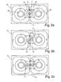
- the Fig. 2a-c each show a cross-sectional view of two Topf Vietnameseresonatoren T1, T2 within a housing G with an intermediate pot wall 4.
- the Topf Vietnamesee T1, T2 have each Inner conductor 21, 22 on, with an axial extent perpendicular to the plane.
- the coupling window 5 can be seen, in which the coupling means 7 is arranged.
- the orientation of the rod member 8 parallel to the inner conductors 21, 22 can be seen, as well as the insulator 15, which surrounds the rod member 8 in the region of the finger holder 14 concentrically.
- the finger elements 12, 13 are aligned here parallel and symmetrical to the rod element 8.
- the coupling means 7 is adjusted about the axis of rotation such that the finger plane 16 with the window plane a small angle a, typically a ⁇ 10 °, preferably near 0 °, includes. This results in a compensation of a parasitic inductive coupling via the coupling window 5 itself with a slight capacitive coupling, which is caused by the slightly rotated from the window plane coupling element.
- Fig. 2b shows a rotational position of the coupling means 7, in which the finger plane 17 with the window plane 16 includes any angle a between 90 ° and 0 °.
- the maximum capacitive coupling between both cup-circle resonators T1, T2 is in the in Figure 2c illustrate rotational position achieved in which the finger plane 17 with the window plane 16 form an angle a of 90 ° and the distance of the finger elements to the respective inner conductors 21, 22 of the cup-circle resonators T1, T2 is the lowest.
- Fig. 3 shows an RF filter consisting of six Topf Vietnamese resonators T1 to T6, which are arranged in two rows Z1, Z2.
- the HF-moderate main path H is in ascending order by the sequence of Topf Vietnamese resonatoren
- the coupling in the main path H takes place inductively.
- a capacitive cross-coupling QK according to the invention between the pot circuits T2 and T5 is provided, ie along two arranged in a column SP cup-ring resonators, with a solution according trained, rotatably mounted coupling means, preferably one in the FIGS. 1 and 2 illustrated coupling means with rod and finger elements, realized.
Landscapes
- Physics & Mathematics (AREA)
- Electromagnetism (AREA)
- Control Of Motors That Do Not Use Commutators (AREA)
Abstract
Description
- Die Erfindung betrifft eine HF-Filteranordnung mit mindestens zwei kapazitiv gekoppelten Topfkreis-Resonatoren, die über eine gemeinsame, elektrisch leitende Topfwand oder über jeweils elektrisch miteinander verbundene Topfwände gekoppelt sind, wobei in der gemeinsamen Topfwand oder in den elektrisch miteinander verbundenen Topfwänden ein Koppelfenster eingebracht ist, das vollständig von elektrisch leitendem Material umschlossen und in dem ein Koppelmittel mit variabel einstellbarer Kapazität eingebracht ist. Ferner wird ein HF-Filter beschrieben, das eine Vielzahl miteinander gekoppelte Topfkreis-Resonatoren umfasst, die arrayförmig längs wenigstens zweier Zeilen und wenigstens zweier Spalten angeordnet sind, wobei die Kopplung zwischen zwei in Zeilenrichtung angeordneter Topfkreis-Resonatoren induktiv ausgebildet ist und die Kopplung wenigstens zweier in Spaltenanordnung angrenzende Topfkreis-Resonatoren kapazitiv erfolgt. Schließlich wird ein Verfahren zur Variation einer elektromagnetischen Koppelstärke zwischen zwei Topfkreis-Resonatoren erläutert.
- In Sende- bzw. Antennenanlagen zur Abstrahlung von HF-Signalen, bspw. in Form von Telekommunikations-, Fernseh- oder Radiosignalen, werden für gewöhnlich Bandfilter zwischen der Sendeverstärkereinheit und der Antenne angeordnet, um eventuell im Verstärker-Ausgangssignal vorhandene Störsignale in Form von am Nutzfrequenzbereich unmittelbar angrenzenden störenden Neben- oder Seitenlinien zu unterdrücken. Dies stellt eine besondere technische Herausforderung dar, zumal derartige Störlinien bzw. Störsignalanteile in Nachbarkanälen aufgrund des geringen Frequenzabstandes zum Nutzfrequenzfrequenzbereich, der durch den jeweiligen Sendekanal und dessen Mittenfrequenz und Kanalbandbreite vorgegeben ist, möglichst ohne relevante Beeinträchtigung des Nutzfrequenzbereiches beseitigt oder unterdrückt werden sollen. Zudem gelten für die Übertragung von HF-Signalen in bestimmten Frequenzbändern bzw. -bereichen verbindliche Standards, so bspw. für die Übertragung von digitalen Inhalten, wie bspw. Fernsehen, Radio, Mehrkanaltonsignale, die Einhaltung des DVB, ATSC etc. Standards.
- Um die geforderten spektralen Eigenschaften für die Nutzsignale mit großen HF-Leistungen erzielen zu können, werden Bandfilter mit HF-mäßig miteinander gekoppelten Topfkreisfilter eingesetzt, die so angeordnet sind, dass zwischen zwei HF-mäßig nicht aufeinanderfolgenden Topfkreisen eine Quer- bzw. Gegenkopplung vorgesehen ist. Ein derartiger Bandfilter aus Topfkreisen ist in der
DE 199 16 605 C1 beschrieben. Durch die Gegenkopplung von HF-mäßig nicht aufeinanderfolgenden Topfkreisen versteilen sich die Flanken der Durchlasskurve und erhöht sich damit die Selektivität des Bandfilters. Dabei nimmt man in Kauf, dass die Durchlasskurve des Filters im Sperrbereich zu niedrigeren und höheren Frequenzen Dämpfungsminima aufweist (sogenannte CAUER-Charakteristik), während die Durchlasskurve nicht gegengekoppelter Bandfilter zu dem unteren und dem oberen Sperrbereich hin einen monoton wachsenden Dämpfungsverlauf (TSCHEBYSCHEFF-Charakteristik) hat. Bei dem mehrkreisigen, gegengekoppelten Bandfilter nach derDE 199 16 605 C1 sind die gegenzukoppelnden Topfkreise so angeordnet sind, dass die Topfkreise mechanisch benachbart liegen und die Gegenkopplung als eine in den einen Topfkreis eintauchende Schleife ausgebildet ist, die durch einen in der Trennwand zwischen beiden benachbarten Topfkreisen ausgebildeten Schlitz hindurch mit einem Stempel in dem anderen Topfkreis verbunden ist. Die Schleife und der Stempel bilden zweckmäßig ein einheitliches Leitungsstück, dessen Eintauchtiefe in die Topfkreise und dadurch der Gegenkopplungsgrad variierbar sind. Die Schleife bewirkt eine induktive Kopplung, der Stempel hingegen eine kapazitive Kopplung. Der Übergang von der induktiven zu der kapazitiven Kopplung bewirkt gleichzeitig eine notwendige Phasendrehung um 180°. Wird beispielsweise das Filter in an sich bekannter Weise auf eine niedrigere Mittenfrequenz abgestimmt und soll dabei die Gegenkopplung der betreffenden Topfkreise konstant bleiben, so muss hierzu die Fläche der in den einen Topfkreis eintauchenden Schleife vergrößert werden. Dies geschieht durch Vergrößerung der Eintauchtiefe des Leitungsstücks. Mit diesem verschiebt sich auch der die kapazitive Kopplung bewirkende Stempel in dem anderen Topfkreis. - Ferner ist ein Bandpassfilter mit gegengekoppelten Topfkreisen T1, T2 bekannt, bei dem eine gemeinsame Wand W zweier mechanisch benachbarter Topfkreise T1, T2 ein Fenster F aufweist (siehe
Fig. 4b ). Im Fensterbereich ist ein brückenartiges, symmetrisch zur Fensterebene ausgebildetes, kapazitives Koppelelement K angeordnet, das auf einem Isolator I abgestützt ist, sieheFig. 4a . Das Koppelelement K weist in der Symmetrie-/Fensterebene eine Bohrung parallel zu den Innenleitern der Topfkreisresonatoren auf, in der mittels des Isolators I elektrisch isoliert ein Koppelstift KS axial verschiebbar gelagert ist. Befindet sich der Koppelstift Stift KS in einer nicht eingeschobenen Position, so ist die kapazitive Kopplung zwischen den Topfkreisresonatoren T1, T2 maximal. Wird der Koppelstift KS in die Bohrung des Isolators I eingeschoben, so wirkt dieser als variable Kapazität gegen Masse, d.h. die effektive kapazitive Kopplung zwischen den Topfkreisresonatoren wird verringert. - Der Nachteil einer derartigen Anordnung besteht darin, dass immer ein durch die Geometrie des brückenartigen Koppelelements bestimmtes Maximum an Leistung ausgekoppelt wird, wovon jedoch bei der Abstimmung des Filters ein Teil der ausgekoppelten Leistung durch eine variable Kapazität gegen Masse kurzgeschlossen wird.
- Aus
DE 12 22 600 B ist eine durchstimmbare Filteranordnung aus wenigstens zwei gekoppelten Resonanzleitungsabschnitten bekannt, bei der die Kopplung über eine Veränderung der radialen Erstreckung zweier linear beweglicher Stiftteile in die Resonanzleitungsabschnitte quer zu den Resonatorlängsachsen variiert wird. - Die Aufgabe der Erfindung besteht darin, die kapazitive Querkopplung zwischen zwei Topfkreis-Resonatoren zu verbessern, besonders hinsichtlich der Variationsmöglichkeiten des Koppelfaktors und der Minimierung vorhandener Verluste.
- Die Aufgabe der Erfindung wird gelöst durch eine HF-Filteranordnung gemäß Anspruch 1, ein HF-Filter gemäß den Ansprüchen 10 und 11 sowie durch ein Verfahren zur Variation einer elektromagnetischen Koppelstärke gemäß Anspruch 12.
- Die lösungsgemäßen Vorrichtungen und das lösungsgemäße Verfahren in vorteilhafter Weise weiterbildende Merkmale sind Gegenstand der Unteransprüche sowie der weiteren Beschreibung zu entnehmen.
- Der Anspruch 1 bezieht sich auf eine HF-Filteranordnung mit mindestens zwei Topfkreis-Resonatoren, die über eine gemeinsame, elektrisch leitende Topfwand oder über jeweils elektrisch miteinander verbundene Topfwände gekoppelt sind, wobei in der gemeinsamen Topfwand oder in den elektrisch miteinander verbundenen Topfwänden ein Koppelfenster eingebracht ist, das vollständig von elektrisch leitendem Material umschlossen und in dem ein Koppelmittel mit variabel einstellbarer Kapazität eingebracht ist.
- Eine lösungsgemäße HF-Filteranordnung zeichnet sich dadurch aus, dass das Koppelmittel ein elektrisch leitendes Stabelement mit einer Stabachse sowie zwei Stabelementenden aufweist, das beidseitig über die Stabelementenden mit dem das Koppelfenster umschließenden elektrisch leitenden Material elektrisch leitend verbunden ist, und dass elektrisch isoliert zum Stabelement wenigstens zwei elektrisch miteinander verbundene, aus elektrisch leitendem Material gefertigte Fingerelemente am Stabelement befestigt sind, um eine mit der Stabachse zusammenfallende Drehachse drehbar gelagert sind.
- Erfindungswesentlich ist, dass durch das elektrisch leitende und elektrisch leitend mit dem umgebenden Material verbundene Stabelement das Koppelfenster in zwei kleinere Teilfenster unterteilt wird, wobei eine durch die Fensterfläche hindurch wirkende parasitäre induktive Kopplung durch diese Teilfensterung weitgehend unterdrückt bzw. kompensiert werden kann. So genügt bereits ein kleiner kapazitiver Beitrag zur Kopplung aus, um eine vorhandene parasitäre induktive Kopplung zu kompensieren. Somit ist im Vergleich mit bekannten Anordnungen eine viel stärkere kapazitive Kopplung zwischen den Topfkreis-Resonatoren möglich.
- Mit der erfindungsgemäßen Anordnung kann damit die Größe des Kopplungsfaktors in einem großen Bereich variiert werden, so dass die Filtercharakteristik eines Bandpassfilters für viele unterschiedliche Broadcast-Standards, wie z.B. ATSC, DVB-T, ISDB-T einstellbar sind. Dabei kann der Kopplungsfaktor zwischen minimaler Kopplung, d.h. Kopplungsfaktor Null, und maximaler Kopplung mit im Prinzip einer ¼-Drehung der Fingerelemente um die Drehachse variiert werden. Bei minimaler Kopplung befinden sich die Fingerelemente näherungsweise in einer dem Fenster zuordenbaren Ebene. Die Finger entfalten dabei eine zusätzliche induktive Schirmwirkung, indem sie das ursprüngliche Fenster im Zusammenwirken mit dem Stabelement in vier kleinere Fenster unterteilen.
- Durch die lösungsgemäße kapazitive Kopplungsweise ist ein größerer Abstand des Koppelmittels, d.h. der Fingerelemente und das Stabelement, zu den Resonatoren realisierbar, wodurch eine höhere Spannungsfestigkeit die Folge ist. Somit kann die Bauweise der HF-Filteranordnung auch für größere Leistungen ausgelegt werden als es bei den bekannten vergleichbaren Filteranordnungen der Fall ist.
- In einer bevorzugten Ausführungsform teilt das Stabelement das Koppelfenster in zwei im Wesentlichen symmetrische Fensterbereiche, d.h. das Stabelement blockiert die Mitte des ursprünglichen Koppelfensters, wodurch sehr geringe Kopplungsfaktoren realisierbar sind.
- In einer bevorzugten Ausführungsform zeichnet sich die HF-Filteranordnung dadurch aus, dass das Stabelement drehbar um die Drehachse innerhalb des Koppelfensters angeordnet ist und die wenigstens zwei Fingerelemente drehfest an dem Stabelement angebracht sind. Hierzu eignet sich insbesondere eine Fingeraufnahme aus elektrisch leitendem Material, an der die Fingerelemente angeordnet sind. Die Fingeraufnahme weist eine Bohrung auf, die von dem elektrisch leitenden Stabelement durchragt wird. Zur elektrischen Isolation des Stabelements gegen die Fingeraufnahme bzw. die Fingerelemente ist ein Isolator eingebracht, der das Stabelement zumindest teilweise im Bereich der Fingeraufnahme bevorzugt konzentrisch bzgl. der Drehachse umgibt.
- Die Spalte zwischen den Fingerelementen und dem Koppelfenster müssen nicht zwingend parallel sein, d.h. die Fingerelemente können beispielsweise bzgl. der Drehachse in radialer Richtung geneigt angeordnet sein.
- Besonders bevorzugt sind jedoch stabförmig ausgebildete Fingerelemente, die parallel sowie gleichbeabstandet zur Drehachse angeordnet sind. Vorzugsweise sind die Fingerelemente zum Stabelement diametral gegenüberliegend angeordnet sind. Allerdings ist auch eine im Vergleich zur diametralen Anordnung leicht versetzte Anordnung denkbar, d.h. ein Winkel, der durch die gedachten, radialen Verbindungslinien zwischen jeweils einem Fingerelement und dem Stabelement gebildet ist, entspricht nicht 180°, sondern weicht hiervon ab, vorzugsweise in eine Winkelbereich von α ≤ ±15 ° von der 180°-Stellung, d.h. eine erste Ebene, die durch ein Fingerelement und das Stabelement aufgespannt wird, schneidet eine zweite Ebene, die durch das Stabelement und das andere Fingerelement aufgespannt wird, unter dem Winkel α, für den gilt α ≤ 15°.
- Allgemein gilt, dass die Spalte zwischen den Fingerelementen und dem Koppelfenster nicht zwingend parallel ausgebildet sein müssen, d.h. die Fingerelemente können beispielsweise bzgl. der Drehachse in radialer Richtung geneigt sein.
- Ebenso kann die Gestalt des Stabelementes, der Fingerelemente und der Fingeraufnahme beliebige Formen annehmen. Bezüglich des Stabelements und der Fingerelemente sind grundsätzlich Varianten bzgl. der Querschnittsform, z.B. rund, eckig, oval, symmetrisch, unsymmetrisch, hohl oder aus Vollmaterial gefertigt, möglich, ebenso wie Querschnittsvariationen in axialer Richtung, z.B. ballig oder tailliert, stetige oder unstetige Querschnittsänderungen. Sämtliche Elemente des Koppelmittels, d.h. Fingerelemente, Stabelement, Fingeraufnahme, sind vorzugsweise oberflächenbehandelt, d.h. beispielsweise mit einer besonders leitfähigen Oberfläche versehen, wie z.B. Silber, Kupfer, Gold etc., um die Wirkungsweise zu optimieren.
- In einer besonderen Ausführungsform ist das Stabelement parallel zur Längserstreckung eines Innenleiters wenigstens eines der mindestens zwei Topfkreis-Resonatoren ausgerichtet.
- Weiterhin bevorzugt ist es die mindestens zwei Topfkreis-Resonatoren von einem Gehäuse elektrisch leitend zumindest teilweise, vorzugsweise vollständig zu umfassen und das Stabelement mittelbar oder unmittelbar von außerhalb des Gehäuses mit Hilfe eines Betätigungsmittels drehbar auszubilden. Dabei ist es besonders bevorzugt, dass die Fingerelemente um die Drehachse in einem Drehwinkelbereich von mindestens 80°, vorzugsweise mindestens 90°, besonders bevorzugt von 180°, drehbar gelagert sind. Besonders bevorzugt ist, dass zur Fixierung der Drehwinkeleinstellung ein Feststellmittel vorgesehen ist, wodurch das Betätigungsmittel, mit dem der Drehwinkel der Fingerelemente eingestellt wird, gegen unabsichtliches Verstellen gesichert werden kann.
- Die lösungsgemäße Filteranordnung zeichnet in vorteilhafter Weise durch die bauliche Kompaktheit aus, zumal das vollständige Koppelmittel inklusive der Betätigung und der Anbringung innerhalb des minimalen Bauraums der Filteranordnung integrierbar ist. Insbesondere sind keine unterschiedlich weit, je nach Kopplungsgrad, in die Umgebung des Filtergehäuses ragende Stellelemente erforderlich, wie dies bei den bekannten vergleichbaren Filteranordnungen der Fall ist. Des Weiteren ist eine Betätigung des Koppelmittels von zwei gegenüberliegenden Seiten des Filtergehäuses möglich, sofern das Betätigungsmittel beidseitig nach Außen geführt wird, wohingegen aus dem Stand der Technik bekannte Querkopplungen üblicherweise nur von einer Filtergehäuseseite aus betätigbar sind.
- Auf der Grundlage der vorstehend beschriebenen, kapazitiven Kopplungsweise zwischen zwei Topfkreisresonatoren lässt sich ferner ein HF-Filter mit einer Vielzahl miteinander gekoppelter Topfkreis-Resonatoren aufbauen, die arrayförmig längs wenigstens zweier Zeilen und wenigstens zweier Spalten angeordnet sind, wobei die Kopplung zwischen zwei in Zeilenrichtung angeordneter Topfkreis-Resonatoren induktiv ausgebildet ist. Hierbei sei vorausgesetzt, dass die jeweils in Zeilen angeordneten Topfkreis-Resonatoren HF-mäßig gekoppelt sind. Für eine serielle HF-mäßige Kopplung zweier parallel verlaufender Zeilen sind lediglich zwei Topfkreis-Resonatoren, die sich am Zeilenende längs einer Spalte gegenüberstehen, ebenfalls HF-mäßig gekoppelt. Auf diese Weise werden in U-Form seriell angeordnete Topfkreis-Resonatoren HF-mäßig miteinander gekoppelt. Alle Topfkreis-Resonatoren in der U-Formanordnung, die sich spaltenweise gegenüberstehen, sind ansonsten HF-mäßig nicht gekoppelt.
- Das HF-Filter zeichnet sich dadurch aus, dass wenigstens ein Paar von Topfkreis-Resonatoren, die in Spaltenrichtung angeordnet sind, als HF-Filteranordnung nach einem der Ansprüche 1 bis 9 ausgebildet ist, d.h. in den beiden in Spaltenrichtung über eine gemeinsame Wand aneinandergrenzenden Topfkreis-Resonatoren befindet sich ein Fenster, in dem das Stabelement mit den daran drehbar angeordneten Fingerelementen vorgesehen ist, um die Koppelkapazität und damit die Koppelstärke zwischen den beiden in Spaltenrichtung angeordneten Topfkreis-Resonatoren stufenlos zu variieren. Selbstverständlich lässt sich die lösungsgemäße, variabel einstellbare Koppelkapazität auch im Einsatz dieses HF-Filters nach den vorstehend beschriebenen Ausführungsvarianten modifizieren.
- Besonders bevorzugt ist eine Anordnung aus mindestens sechs Topfkreis-Resonatoren, die in zwei Zeilen angeordnet sind. Die Einkopplung des zu filternden HF-Signals erfolgt dabei in Zeilenrichtung vorzugsweise induktiv in einen ersten Topfkreis-Resonator. Der Hauptausbreitungspfad erstreckt sich in Zeilenrichtung durch die in der ersten Zeile liegenden Topfkreis-Resonatoren 1 bis 3, dann in Spaltenrichtung durch die Kopplung der Topfkreis-Resonatoren 3 und 4 und anschließend wiederum in Zeilenrichtung (allerdings nunmehr entgegengesetzt) durch die in der zweiten Zeile liegenden Topfkreis-Resonatoren 4 bis 6. Ein gefiltertes HF-Signal kann in Zeilenrichtung aus dem Topfkreis-Resonator 6 ausgekoppelt werden. Die Querkopplung ist zwischen den HF-mäßig nicht benachbarten Topfkreis-Resonatoren 2 und 5 entsprechend der erfindungsgemäßen HF-Filteranordnung realisiert.
- Ein zweites lösungsgemäßes HF-Filter weist eine Vielzahl miteinander gekoppelter Topfkreis-Resonatoren auf, die arrayförmig längs wenigstens zweier Zeilen und wenigstens zweier Spalten angeordnet sind, wobei die Kopplung zwischen wenigstens zwei TopfkreisResonatoren, die in Spaltenrichtung angeordnet sind, induktiv ausgebildet ist. Es zeichnet sich dadurch aus, dass die Kopplung zwischen jeweils zwei Topfkreis-Resonatoren, die in Zeilenrichtung angeordnet sind, kapazitiv ausgebildet ist, und dass die zwei Topfkreis-Resonatoren als HF-Filteranordnung nach einem der Ansprüche 1 bis 9 ausgebildet sind.
- Der Betriebs- und Funktionsweise des vorstehend erläuterten HF-Filters liegt ein lösungsgemäßes Verfahren zur Variation der elektromagnetischen Koppelstärke zwischen zwei Topfkreis-Resonatoren zugrunde, das die konstruktiven Vorgaben einer HF-Filteranordnung nach den Ansprüchen 1 bis 9 nutzt. Hierbei werden zur kontinuierlichen Variation der kapazitiven Koppelstärke zwischen zwei Topfkreis-Resonatoren die Fingerelemente, die gemeinsam mit dem Stabelement eine Fingerebene aufspannen, aus einer ersten Position, in der sich die Fingerelemente in einer oder im Bereich einer dem Koppelfenster zuordenbaren Koppelfensterebene befinden, ausschließlich durch kontinuierliches Verdrehen um die Drehachse in eine zweite Position überführt, in der die den Fingerelementen zuordenbare Fingerebene einen Winkel a mit der Koppelfensterebene einschließt.
- Bemerkenswert ist, dass durch Verdrehen der Fingerebene in die erste Position, in der die Fingerebene mit der Koppelfensterebene einen Winkel a von 0° ≤ a ≤ 10° einschließt, eine geringste Koppelstärke, vorzugsweise eine Koppelstärke von Null, eingestellt werden kann, und dass durch Verdrehen in die zweite Position, in der die Fingerebene mit der Koppelfensterebene einen Winkel α von 85° ≤ a ≤ 95°, vorzugsweise a = 90° einschließt, eine maximale kapazitive Koppelstärke einstellbar ist.
-
-
Fig. 1 : Koppelfenster mit lösungsgemäß ausgebildeten Koppelmittel, -
Fig. 2 a-c : Sequenzbilddarstellungen eines Koppelmittels in unterschiedlichen Drehstellungen innerhalb eines Koppelfensters, -
Fig. 3 : HF-Filter mit sechs HF-mäßig gekoppelten Topfkreisen und -
Fig. 4 : bekannte Koppelanordnung durch ein Koppelfenster zwischen zwei benachbart angeordnete Topfkreis-Resonatoren. - Die
Fig. 1 zeigt einen Ausschnitt aus der gemeinsamen Topfwand 4 zwischen zwei kapazitiv gekoppelten Resonatoren (nicht dargestellt) mit dem Koppelfenster 5, in dem das Koppelmittel 7, angeordnet ist. Das Koppelfenster 5 ist von elektrisch leitendem Material umgeben, wobei beispielsweise drei Fensterseiten Seiten durch das elektrisch leitende Material der gemeinsamen Topfwand 4 begrenzt sind und die vierte elektrisch leitende Begrenzung des Koppelfensters bspw. durch ein abnehmbares Deckelelement 4' der HF-Filteranordnung gebildet ist, mit dem die Topfkreisresonatoren in einer Ebene senkrecht zu den Innenleitern geschlossen werden. Das Deckelelement ist somit Teil des Gehäuses. - Das Koppelmittel 7 weist ein elektrisch leitendes Stabelement 8 mit einer Stabachse 9 sowie zwei Stabelementenden 10, 11 auf, das beidseitig über die Stabelementenden 10, 11 mit dem das Koppelfenster 7 umschließenden elektrisch leitenden Material elektrisch leitend verbunden ist. Elektrisch isoliert zum Stabelement 8 sind wenigstens zwei elektrisch miteinander verbundene, aus elektrisch leitendem Material gefertigte Fingerelemente 12, 13 am Stabelement 8 befestigt. Hierzu ist eine Fingeraufnahme 14 vorgesehen, die die Fingerelemente 12, 13 elektrisch leitend verbindet. Zwischen Fingeraufnahme 14 und Stabelement 8 ist ein Isolator vorgesehen, der letztlich für eine elektrische Isolation der Fingerelemente 12, 13 und dem Stabelement 8 sorgt.
- Die Fingerelemente 12, 13 sind drehfest über die Fingeraufnahme 14 und Isolator mit dem Stabelement 8 verbunden und somit um eine mit der Stabachse 9 zusammenfallende Drehachse 19 drehbar gelagert.
- Die
Fig. 2a-c zeigen jeweils eine Querschnittsansicht zweier Topfkreisresonatoren T1, T2 innerhalb eines Gehäuses G mit einer zwischenliegenden Topfwand 4. Die Topfkreise T1, T2 weisen jeweils Innenleiter 21, 22 auf, mit einer axialen Erstreckung senkrecht zur Zeichenebene. In der gemeinsamen Topfwand 4 ist das Koppelfenster 5 zu erkennen, in dem das Koppelmittel 7 angeordnet ist. In dieser Ansicht ist die Ausrichtung des Stabelements 8 parallel zu den Innenleitern 21, 22 zu erkennen, ebenso der Isolator 15, der das Stabelement 8 im Bereich der Fingeraufnahme 14 konzentrisch umgibt. Die Fingerelemente 12, 13 sind hier parallel und symmetrisch zum Stabelement 8 ausgerichtet. - In den
Figuren 2a-c sind jeweils unterschiedliche Stellungen des Koppelmittels 7 bezüglich einer durch die Topfwand 4 definierten Fensterebene 16 dargestellt. - Dabei bewirkt eine Stellung des Koppelmittels 7, wie in
Fig. 2a gezeigt, eine minimale kapazitive Kopplung (Null-Kopplung) zwischen den Topfkreis-Resonatoren T1, T2. in diesem Fall ist das Koppelmittel 7 um die Drehachse derart eingestellt, dass die Fingerebene 16 mit der Fensterebene einen kleinen Winkel a, typischerweise a ≤ 10°, vorzugsweise nahe 0°, einschließt. Hier kommt es zu einer Kompensation einer parasitären induktiven Kopplung über das Koppelfenster 5 selbst mit einer geringfügigen kapazitiven Kopplung, die durch das leicht aus der Fensterebene gedrehte Koppelelement bewirkt wird. -
Fig. 2b zeigt eine Drehstellung des Koppelmittels 7, in der die Fingerebene 17 mit der Fensterebene 16 einen beliebigen Winkel a zwischen 90° und 0° einschließt. - Die maximale kapazitive Kopplung zwischen beiden Topfkreis-Resonatoren T1, T2 wird in der in
Figur 2c illustrieren Drehstellung erzielt, bei der die Fingerebene 17 mit der Fensterebene 16 einen Winkel a von 90° einschließen und der Abstand der Fingerelemente zu den jeweiligen Innenleitern 21, 22 der Topfkreis-Resonatoren T1, T2 am geringsten ist. -
Fig. 3 zeigt ein HF-Filter bestehend aus sechs Topfkreis-Resonatoren T1 bis T6, die in zwei Zeilen Z1, Z2 angeordnet sind. Der HF-mäßige Hauptpfad H wird durch die Abfolge der Topfkreisresonatoren in aufsteigender - Nummerierung gebildet, siehe Pfeildarstellung. Die Kopplung im Hauptpfad H erfolgt induktiv. Zusätzlich ist eine erfindungsgemäße kapazitive Querkopplung QK zwischen den Topfkreisen T2 und T5 vorgesehen, also längs zweier in einer Spalte SP angeordnete Topfkreis-Resonatoren, die mit einem lösungsgemäß ausgebildeten, drehbar gelagerten Koppelmittel, vorzugsweise eines in den
Figuren 1 und2 illustrierten Koppelmittels mit Stab- und Fingerelementen, realisiert ist.
Claims (13)
- HF-Filteranordnung (1) mit mindestens zwei Topfkreis-Resonatoren (2, 3), die über eine gemeinsame, elektrisch leitende Topfwand (4) oder über jeweils elektrisch miteinander verbundene Topfwände gekoppelt sind, wobei in der gemeinsamen Topfwand (4) oder in den elektrisch miteinander verbundenen Topfwänden ein Koppelfenster (5) eingebracht ist, das vollständig von elektrisch leitendem Material (6) umschlossen und in dem ein Koppelmittel (7) mit variabel einstellbarer Kapazität eingebracht ist,
dadurch gekennzeichnet, dass das Koppelmittel (7) ein elektrisch leitendes Stabelement (8) mit einer Stabachse (9) sowie zwei Stabelementenden (10, 11) aufweist, das beidseitig über die Stabelementenden (10, 11) mit dem das Koppelfenster (7) umschließenden elektrisch leitenden Material (6) elektrisch leitend verbunden ist, und
dass elektrisch isoliert zum Stabelement (8) wenigstens zwei elektrisch miteinander verbundene, aus elektrisch leitendem Material gefertigte Fingerelemente (12, 13) am Stabelement (8) derart befestigt sind, dass die Fingerelemente (12, 13) um eine mit der Stabachse (9) zusammenfallende Drehachse (19) drehbar gelagert sind. - HF-Filteranordnung nach Anspruch 1,
dadurch gekennzeichnet, dass das Stabelement (8) drehbar um die Drehachse (19) innerhalb des Koppelfenster (5) angeordnet ist und die wenigstens zwei Fingerelemente (12, 13) drehfest an dem Stabelement (8) angebracht sind. - HF-Filteranordnung nach Anspruch 1 oder 2,
dadurch gekennzeichnet, dass die Fingerelemente (12, 13) stabförmig ausgebildet und parallel sowie gleichbeabstandet zur Drehachse (19) angeordnet sind. - HF-Filteranordnung nach einem der Ansprüche 1 bis 3,
dadurch gekennzeichnet, dass die Fingerelemente (12, 13) zum Stabelement (8) diametral gegenüberliegend angeordnet sind. - HF-Filteranordnung nach einem der Ansprüche 1 bis 3,
dadurch gekennzeichnet, dass die Fingerelemente (12, 13) zum Stabelement gegenüberliegend angeordnet sind,
dass ein Fingerelement und das Stabelement eine erste Ebene aufspannen und dass das andere Fingerelement und das Stabelement eine zweite Ebene aufspannen, und
dass sich die erste und zweite Ebene unter einem Winkel α schneiden, für den gilt: α ≤ 15°. - HF-Filteranordnung nach Anspruch 1 oder 2,
dadurch gekennzeichnet, dass die Fingerelemente (12, 13) stabförmig ausgebildet und zum Stabelement gegenüberliegend angeordnet sind, und dass die Fingerelemente relativ zur der Drehachse in radialer Richtung geneigt angeordnet sind. - HF-Filteranordnung nach einem der Ansprüche 1 bis 6,
dadurch gekennzeichnet, dass das Stabelement (8) parallel zur Längserstreckung eines Innenleiters (20, 21) wenigstens eines der mindestens zwei Topfkreis-Resonatoren (1, 2) ausgerichtet ist. - HF-Filteranordnung nach Anspruch 2,
dadurch gekennzeichnet, dass die mindestens zwei Topfkreis-Resonatoren (1, 2) von einem Gehäuse (G) zumindest teilweise umgeben sind und dass das Stabelement (8) mittelbar oder unmittelbar von außerhalb des Gehäuses (22) drehbar ist. - HF-Filteranordnung nach Anspruch 1 bis 8,
dadurch gekennzeichnet, dass die Fingerelemente (12, 13) um die Drehachse (19) in einem Drehwinkelbereich a von mindestens 80°, vorzugsweise mindestens 90°, besonders bevorzugt von mindestens 180°, drehbar sind. - HF-Filter mit einer Vielzahl miteinander gekoppelter Topfkreis-Resonatoren (1, 2), die arrayförmig längs wenigstens zweier Zeilen und wenigstens zweier Spalten angeordnet sind, wobei die Kopplung zwischen zwei in Zeilenrichtung angeordneter Topfkreis-Resonatoren induktiv ausgebildet ist,
dadurch gekennzeichnet, dass wenigstens ein Paar von Topfkreis-Resonatoren, die in Spaltenrichtung angeordnet sind, als HF-Filteranordnung nach einem der Ansprüche 1 bis 9 ausgebildet sind. - HF-Filter mit einer Vielzahl miteinander gekoppelter Topfkreis-Resonatoren, die arrayförmig längs wenigstens zweier Zeilen und wenigstens zweier Spalten angeordnet sind, wobei die Kopplung zwischen wenigstens zwei TopfkreisResonatoren, die in Spaltenrichtung angeordnet sind, induktiv ausgebildet ist,
dadurch gekennzeichnet, dass die Kopplung zwischen jeweils zwei Topfkreis-Resonatoren, die in Zeilenrichtung angeordnet sind, kapazitiv ausgebildet ist, und dass die zwei Topfkreis-Resonatoren als HF-Filteranordnung nach einem der Ansprüche 1 bis 9 ausgebildet sind. - Verfahren zur Variation einer elektromagnetischen Koppelstärke zwischen zwei Topfkreis-Resonatoren, die im Wege einer HF-Filteranordnung nach den Ansprüchen 1 bis 9 ausgebildet und miteinander gekoppelt sind, bei dem die Fingerelemente, die gemeinsam mit dem Stabelement eine Fingerebene aufspannen, aus einer ersten Position, in der sich die Fingerelemente in einer oder im Bereich einer dem Koppelfenster zuordenbaren Koppelfensterebene befinden, ausschließlich durch kontinuierliches Verdrehen um die Drehachse in einer zweite Position überführt werden, in der die den Fingerelementen zuordenbare Fingerebene einen Winkel α mit der Koppelfensterebene einschließt.
- Verfahren nach Anspruch 12,
dadurch gekennzeichnet, dass durch Verdrehen der Fingerebene in die erste Position, in der die Fingerebene mit der Koppelfensterebene einen Winkel a von 0° ≤ a ≤ 10° einschließt, eine geringste Koppelstärke, vorzugsweise keine Koppelstärke, eingestellt wird, und dass durch Verdrehen in die zweite Position, in der die Fingerebene mit der Koppelfensterebene einen Winkel a von 85° ≤ a ≤ 95°, vorzugsweise a = 90° einschließt, eine maximale kapazitive Koppelstärke eingestellt wird.
Applications Claiming Priority (1)
| Application Number | Priority Date | Filing Date | Title |
|---|---|---|---|
| DE201110016487 DE102011016487A1 (de) | 2011-04-08 | 2011-04-08 | HF-Filteranordnung sowie Verfahren zur Variation einer elektromagnetischen Koppelstärke zwischen zwei Topfkreis-Resonatoren |
Publications (3)
| Publication Number | Publication Date |
|---|---|
| EP2509152A2 true EP2509152A2 (de) | 2012-10-10 |
| EP2509152A3 EP2509152A3 (de) | 2013-04-03 |
| EP2509152B1 EP2509152B1 (de) | 2016-09-21 |
Family
ID=46021966
Family Applications (1)
| Application Number | Title | Priority Date | Filing Date |
|---|---|---|---|
| EP12002363.5A Active EP2509152B1 (de) | 2011-04-08 | 2012-03-30 | HF-Filteranordnung sowie Verfahren zur Variation einer elektromagnetischen Koppelstärke zwischen zwei Topfkreis-Resonatoren |
Country Status (4)
| Country | Link |
|---|---|
| EP (1) | EP2509152B1 (de) |
| CN (1) | CN102738542A (de) |
| DE (1) | DE102011016487A1 (de) |
| ES (1) | ES2608580T3 (de) |
Cited By (1)
| Publication number | Priority date | Publication date | Assignee | Title |
|---|---|---|---|---|
| CN103066352A (zh) * | 2012-12-31 | 2013-04-24 | 深圳市大富科技股份有限公司 | 滤波器及采用该滤波器的通信射频器件 |
Families Citing this family (6)
| Publication number | Priority date | Publication date | Assignee | Title |
|---|---|---|---|---|
| CN103000982B (zh) * | 2012-12-08 | 2014-09-17 | 宁波泰立电子科技有限公司 | 一种腔体滤波器输入端口耦合线成型机及其加工方法 |
| CN103066353A (zh) * | 2012-12-31 | 2013-04-24 | 深圳市大富科技股份有限公司 | 滤波器及采用该滤波器的通信射频器件 |
| CN105190989B (zh) * | 2013-03-18 | 2018-09-21 | 上海贝尔股份有限公司 | 与带通滤波器一起使用的可调节的耦合器 |
| EP3113281B1 (de) * | 2015-06-30 | 2025-07-30 | Spinner GmbH | Kopplungselement und hohlraumresonatorvorrichtung mit einem kopplungselement |
| CN110544811B (zh) | 2018-05-29 | 2021-08-20 | 上海华为技术有限公司 | 一种滤波器耦合结构以及加工方法 |
| CN112436260A (zh) * | 2020-11-25 | 2021-03-02 | 苏州灿勤通讯技术有限公司 | 新型te模介质谐振器 |
Citations (2)
| Publication number | Priority date | Publication date | Assignee | Title |
|---|---|---|---|---|
| DE1222600B (de) | 1956-06-19 | 1966-08-11 | Siemens Ag | Durchstimmbare Filteranordnung |
| DE19916605C1 (de) | 1999-04-13 | 2001-01-18 | Spinner Gmbh Elektrotech | Mehrkreisiges Bandfilter aus Topfkreisen |
Family Cites Families (4)
| Publication number | Priority date | Publication date | Assignee | Title |
|---|---|---|---|---|
| DE2325401C3 (de) * | 1973-05-18 | 1985-05-15 | Georg Dr.-Ing. 8152 Feldkirchen-Westerham Spinner | Koppelanordnung zwischen Hochfrequenzkreisen |
| US6304160B1 (en) * | 1999-05-03 | 2001-10-16 | The Boeing Company | Coupling mechanism for and filter using TE011 and TE01δ mode resonators |
| SE0004935D0 (sv) * | 2000-12-29 | 2000-12-29 | Allgon Ab | A filter including coaxial cavity resonators |
| US20030090336A1 (en) * | 2001-11-15 | 2003-05-15 | Radzikowski Piotr Olgierd | Adjustable coupler |
-
2011
- 2011-04-08 DE DE201110016487 patent/DE102011016487A1/de not_active Withdrawn
-
2012
- 2012-03-30 ES ES12002363.5T patent/ES2608580T3/es active Active
- 2012-03-30 EP EP12002363.5A patent/EP2509152B1/de active Active
- 2012-04-06 CN CN 201210182403 patent/CN102738542A/zh active Pending
Patent Citations (2)
| Publication number | Priority date | Publication date | Assignee | Title |
|---|---|---|---|---|
| DE1222600B (de) | 1956-06-19 | 1966-08-11 | Siemens Ag | Durchstimmbare Filteranordnung |
| DE19916605C1 (de) | 1999-04-13 | 2001-01-18 | Spinner Gmbh Elektrotech | Mehrkreisiges Bandfilter aus Topfkreisen |
Cited By (2)
| Publication number | Priority date | Publication date | Assignee | Title |
|---|---|---|---|---|
| CN103066352A (zh) * | 2012-12-31 | 2013-04-24 | 深圳市大富科技股份有限公司 | 滤波器及采用该滤波器的通信射频器件 |
| CN103066352B (zh) * | 2012-12-31 | 2016-01-20 | 深圳市大富科技股份有限公司 | 滤波器及采用该滤波器的通信射频器件 |
Also Published As
| Publication number | Publication date |
|---|---|
| EP2509152B1 (de) | 2016-09-21 |
| CN102738542A (zh) | 2012-10-17 |
| EP2509152A3 (de) | 2013-04-03 |
| DE102011016487A1 (de) | 2012-10-11 |
| ES2608580T3 (es) | 2017-04-12 |
Similar Documents
| Publication | Publication Date | Title |
|---|---|---|
| EP2509152B1 (de) | HF-Filteranordnung sowie Verfahren zur Variation einer elektromagnetischen Koppelstärke zwischen zwei Topfkreis-Resonatoren | |
| EP2656435B1 (de) | Abstimmbares hochfrequenzfilter | |
| EP1620913B1 (de) | Hochfrequenzweiche | |
| DE69114216T2 (de) | Abstimmbares Bandpass Filter. | |
| EP2449622B1 (de) | Hochfrequenzfilter | |
| EP2095459A1 (de) | Hochfrequenzfilter mit sperrkreiskopplung | |
| DE102012020979A1 (de) | Abstimmbares Hochfrequenzfilter | |
| DE102004010683B3 (de) | Hochfrequenzfilter | |
| DE102013201685B4 (de) | Leiteranordnung mit dielektrischer Mantelwellensperre | |
| EP3298649B1 (de) | Hochfrequenzleitersystem mit leitungsgebundener hf-durchführung | |
| EP3078074B1 (de) | Hochfrequenzfilter in koaxialer bauweise | |
| EP1812986B1 (de) | Hochfrequenzfilter | |
| DE69932658T2 (de) | Dielektrischer Resonator, dielektrisches Filter und Kommunikationsgerät | |
| EP2920840B1 (de) | Hochfrequenz-sperrfilter | |
| DE69206661T2 (de) | Keramisches Filter | |
| DE2431278C2 (de) | Vierpol-Filter | |
| DE3109651C2 (de) | Kanalsperrfilter | |
| DE102015002579A1 (de) | Hochfrequenzfilter in cavity Bauweise | |
| DE102018105153B4 (de) | Sperrfilteranordnung | |
| EP2533354B1 (de) | Vorrichtung zur Kopplung eines HF- Signals längs eines Signalpfades | |
| DE102004001347B3 (de) | Duplexer mit niedriger Bauhöhe | |
| DE3413242C2 (de) | ||
| DE2620769A1 (de) | Ueber einen grossen bereich abstimmbares filter |
Legal Events
| Date | Code | Title | Description |
|---|---|---|---|
| PUAI | Public reference made under article 153(3) epc to a published international application that has entered the european phase |
Free format text: ORIGINAL CODE: 0009012 |
|
| AK | Designated contracting states |
Kind code of ref document: A2 Designated state(s): AL AT BE BG CH CY CZ DE DK EE ES FI FR GB GR HR HU IE IS IT LI LT LU LV MC MK MT NL NO PL PT RO RS SE SI SK SM TR |
|
| AX | Request for extension of the european patent |
Extension state: BA ME |
|
| PUAL | Search report despatched |
Free format text: ORIGINAL CODE: 0009013 |
|
| AK | Designated contracting states |
Kind code of ref document: A3 Designated state(s): AL AT BE BG CH CY CZ DE DK EE ES FI FR GB GR HR HU IE IS IT LI LT LU LV MC MK MT NL NO PL PT RO RS SE SI SK SM TR |
|
| AX | Request for extension of the european patent |
Extension state: BA ME |
|
| RIC1 | Information provided on ipc code assigned before grant |
Ipc: H01P 5/04 20060101ALI20130227BHEP Ipc: H01P 1/205 20060101AFI20130227BHEP |
|
| 17P | Request for examination filed |
Effective date: 20130918 |
|
| RBV | Designated contracting states (corrected) |
Designated state(s): AL AT BE BG CH CY CZ DE DK EE ES FI FR GB GR HR HU IE IS IT LI LT LU LV MC MK MT NL NO PL PT RO RS SE SI SK SM TR |
|
| GRAP | Despatch of communication of intention to grant a patent |
Free format text: ORIGINAL CODE: EPIDOSNIGR1 |
|
| INTG | Intention to grant announced |
Effective date: 20160630 |
|
| GRAS | Grant fee paid |
Free format text: ORIGINAL CODE: EPIDOSNIGR3 |
|
| GRAA | (expected) grant |
Free format text: ORIGINAL CODE: 0009210 |
|
| AK | Designated contracting states |
Kind code of ref document: B1 Designated state(s): AL AT BE BG CH CY CZ DE DK EE ES FI FR GB GR HR HU IE IS IT LI LT LU LV MC MK MT NL NO PL PT RO RS SE SI SK SM TR |
|
| REG | Reference to a national code |
Ref country code: GB Ref legal event code: FG4D Free format text: NOT ENGLISH |
|
| REG | Reference to a national code |
Ref country code: CH Ref legal event code: EP |
|
| REG | Reference to a national code |
Ref country code: AT Ref legal event code: REF Ref document number: 831701 Country of ref document: AT Kind code of ref document: T Effective date: 20161015 |
|
| REG | Reference to a national code |
Ref country code: IE Ref legal event code: FG4D Free format text: LANGUAGE OF EP DOCUMENT: GERMAN |
|
| REG | Reference to a national code |
Ref country code: DE Ref legal event code: R096 Ref document number: 502012008294 Country of ref document: DE |
|
| REG | Reference to a national code |
Ref country code: SE Ref legal event code: TRGR |
|
| REG | Reference to a national code |
Ref country code: LT Ref legal event code: MG4D Ref country code: NL Ref legal event code: MP Effective date: 20160921 |
|
| PG25 | Lapsed in a contracting state [announced via postgrant information from national office to epo] |
Ref country code: LT Free format text: LAPSE BECAUSE OF FAILURE TO SUBMIT A TRANSLATION OF THE DESCRIPTION OR TO PAY THE FEE WITHIN THE PRESCRIBED TIME-LIMIT Effective date: 20160921 Ref country code: FI Free format text: LAPSE BECAUSE OF FAILURE TO SUBMIT A TRANSLATION OF THE DESCRIPTION OR TO PAY THE FEE WITHIN THE PRESCRIBED TIME-LIMIT Effective date: 20160921 Ref country code: RS Free format text: LAPSE BECAUSE OF FAILURE TO SUBMIT A TRANSLATION OF THE DESCRIPTION OR TO PAY THE FEE WITHIN THE PRESCRIBED TIME-LIMIT Effective date: 20160921 |
|
| REG | Reference to a national code |
Ref country code: NO Ref legal event code: T2 Effective date: 20160921 |
|
| PG25 | Lapsed in a contracting state [announced via postgrant information from national office to epo] |
Ref country code: LV Free format text: LAPSE BECAUSE OF FAILURE TO SUBMIT A TRANSLATION OF THE DESCRIPTION OR TO PAY THE FEE WITHIN THE PRESCRIBED TIME-LIMIT Effective date: 20160921 Ref country code: GR Free format text: LAPSE BECAUSE OF FAILURE TO SUBMIT A TRANSLATION OF THE DESCRIPTION OR TO PAY THE FEE WITHIN THE PRESCRIBED TIME-LIMIT Effective date: 20161222 Ref country code: NL Free format text: LAPSE BECAUSE OF FAILURE TO SUBMIT A TRANSLATION OF THE DESCRIPTION OR TO PAY THE FEE WITHIN THE PRESCRIBED TIME-LIMIT Effective date: 20160921 |
|
| REG | Reference to a national code |
Ref country code: FR Ref legal event code: PLFP Year of fee payment: 6 |
|
| REG | Reference to a national code |
Ref country code: ES Ref legal event code: FG2A Ref document number: 2608580 Country of ref document: ES Kind code of ref document: T3 Effective date: 20170412 |
|
| PG25 | Lapsed in a contracting state [announced via postgrant information from national office to epo] |
Ref country code: RO Free format text: LAPSE BECAUSE OF FAILURE TO SUBMIT A TRANSLATION OF THE DESCRIPTION OR TO PAY THE FEE WITHIN THE PRESCRIBED TIME-LIMIT Effective date: 20160921 Ref country code: EE Free format text: LAPSE BECAUSE OF FAILURE TO SUBMIT A TRANSLATION OF THE DESCRIPTION OR TO PAY THE FEE WITHIN THE PRESCRIBED TIME-LIMIT Effective date: 20160921 |
|
| PG25 | Lapsed in a contracting state [announced via postgrant information from national office to epo] |
Ref country code: IS Free format text: LAPSE BECAUSE OF FAILURE TO SUBMIT A TRANSLATION OF THE DESCRIPTION OR TO PAY THE FEE WITHIN THE PRESCRIBED TIME-LIMIT Effective date: 20170121 Ref country code: SK Free format text: LAPSE BECAUSE OF FAILURE TO SUBMIT A TRANSLATION OF THE DESCRIPTION OR TO PAY THE FEE WITHIN THE PRESCRIBED TIME-LIMIT Effective date: 20160921 Ref country code: PT Free format text: LAPSE BECAUSE OF FAILURE TO SUBMIT A TRANSLATION OF THE DESCRIPTION OR TO PAY THE FEE WITHIN THE PRESCRIBED TIME-LIMIT Effective date: 20170123 Ref country code: CZ Free format text: LAPSE BECAUSE OF FAILURE TO SUBMIT A TRANSLATION OF THE DESCRIPTION OR TO PAY THE FEE WITHIN THE PRESCRIBED TIME-LIMIT Effective date: 20160921 Ref country code: BG Free format text: LAPSE BECAUSE OF FAILURE TO SUBMIT A TRANSLATION OF THE DESCRIPTION OR TO PAY THE FEE WITHIN THE PRESCRIBED TIME-LIMIT Effective date: 20161221 Ref country code: PL Free format text: LAPSE BECAUSE OF FAILURE TO SUBMIT A TRANSLATION OF THE DESCRIPTION OR TO PAY THE FEE WITHIN THE PRESCRIBED TIME-LIMIT Effective date: 20160921 Ref country code: SM Free format text: LAPSE BECAUSE OF FAILURE TO SUBMIT A TRANSLATION OF THE DESCRIPTION OR TO PAY THE FEE WITHIN THE PRESCRIBED TIME-LIMIT Effective date: 20160921 |
|
| REG | Reference to a national code |
Ref country code: DE Ref legal event code: R097 Ref document number: 502012008294 Country of ref document: DE |
|
| PLBE | No opposition filed within time limit |
Free format text: ORIGINAL CODE: 0009261 |
|
| STAA | Information on the status of an ep patent application or granted ep patent |
Free format text: STATUS: NO OPPOSITION FILED WITHIN TIME LIMIT |
|
| PG25 | Lapsed in a contracting state [announced via postgrant information from national office to epo] |
Ref country code: DK Free format text: LAPSE BECAUSE OF FAILURE TO SUBMIT A TRANSLATION OF THE DESCRIPTION OR TO PAY THE FEE WITHIN THE PRESCRIBED TIME-LIMIT Effective date: 20160921 |
|
| 26N | No opposition filed |
Effective date: 20170622 |
|
| REG | Reference to a national code |
Ref country code: DE Ref legal event code: R082 Ref document number: 502012008294 Country of ref document: DE Representative=s name: ROESLER, UWE, DIPL.-PHYS.UNIV., DE |
|
| REG | Reference to a national code |
Ref country code: CH Ref legal event code: PL |
|
| PG25 | Lapsed in a contracting state [announced via postgrant information from national office to epo] |
Ref country code: SI Free format text: LAPSE BECAUSE OF FAILURE TO SUBMIT A TRANSLATION OF THE DESCRIPTION OR TO PAY THE FEE WITHIN THE PRESCRIBED TIME-LIMIT Effective date: 20160921 Ref country code: MC Free format text: LAPSE BECAUSE OF FAILURE TO SUBMIT A TRANSLATION OF THE DESCRIPTION OR TO PAY THE FEE WITHIN THE PRESCRIBED TIME-LIMIT Effective date: 20160921 |
|
| REG | Reference to a national code |
Ref country code: IE Ref legal event code: MM4A |
|
| PG25 | Lapsed in a contracting state [announced via postgrant information from national office to epo] |
Ref country code: LU Free format text: LAPSE BECAUSE OF NON-PAYMENT OF DUE FEES Effective date: 20170330 |
|
| PG25 | Lapsed in a contracting state [announced via postgrant information from national office to epo] |
Ref country code: LI Free format text: LAPSE BECAUSE OF NON-PAYMENT OF DUE FEES Effective date: 20170331 Ref country code: CH Free format text: LAPSE BECAUSE OF NON-PAYMENT OF DUE FEES Effective date: 20170331 Ref country code: IE Free format text: LAPSE BECAUSE OF NON-PAYMENT OF DUE FEES Effective date: 20170330 |
|
| REG | Reference to a national code |
Ref country code: BE Ref legal event code: MM Effective date: 20170331 |
|
| REG | Reference to a national code |
Ref country code: FR Ref legal event code: PLFP Year of fee payment: 7 |
|
| REG | Reference to a national code |
Ref country code: AT Ref legal event code: MM01 Ref document number: 831701 Country of ref document: AT Kind code of ref document: T Effective date: 20170330 |
|
| PG25 | Lapsed in a contracting state [announced via postgrant information from national office to epo] |
Ref country code: BE Free format text: LAPSE BECAUSE OF NON-PAYMENT OF DUE FEES Effective date: 20170331 |
|
| PG25 | Lapsed in a contracting state [announced via postgrant information from national office to epo] |
Ref country code: AT Free format text: LAPSE BECAUSE OF NON-PAYMENT OF DUE FEES Effective date: 20170330 |
|
| PG25 | Lapsed in a contracting state [announced via postgrant information from national office to epo] |
Ref country code: MT Free format text: LAPSE BECAUSE OF FAILURE TO SUBMIT A TRANSLATION OF THE DESCRIPTION OR TO PAY THE FEE WITHIN THE PRESCRIBED TIME-LIMIT Effective date: 20160921 |
|
| PG25 | Lapsed in a contracting state [announced via postgrant information from national office to epo] |
Ref country code: AL Free format text: LAPSE BECAUSE OF FAILURE TO SUBMIT A TRANSLATION OF THE DESCRIPTION OR TO PAY THE FEE WITHIN THE PRESCRIBED TIME-LIMIT Effective date: 20160921 |
|
| PG25 | Lapsed in a contracting state [announced via postgrant information from national office to epo] |
Ref country code: HU Free format text: LAPSE BECAUSE OF FAILURE TO SUBMIT A TRANSLATION OF THE DESCRIPTION OR TO PAY THE FEE WITHIN THE PRESCRIBED TIME-LIMIT; INVALID AB INITIO Effective date: 20120330 |
|
| PG25 | Lapsed in a contracting state [announced via postgrant information from national office to epo] |
Ref country code: CY Free format text: LAPSE BECAUSE OF NON-PAYMENT OF DUE FEES Effective date: 20160921 |
|
| PG25 | Lapsed in a contracting state [announced via postgrant information from national office to epo] |
Ref country code: MK Free format text: LAPSE BECAUSE OF FAILURE TO SUBMIT A TRANSLATION OF THE DESCRIPTION OR TO PAY THE FEE WITHIN THE PRESCRIBED TIME-LIMIT Effective date: 20160921 |
|
| PG25 | Lapsed in a contracting state [announced via postgrant information from national office to epo] |
Ref country code: TR Free format text: LAPSE BECAUSE OF FAILURE TO SUBMIT A TRANSLATION OF THE DESCRIPTION OR TO PAY THE FEE WITHIN THE PRESCRIBED TIME-LIMIT Effective date: 20160921 |
|
| PG25 | Lapsed in a contracting state [announced via postgrant information from national office to epo] |
Ref country code: HR Free format text: LAPSE BECAUSE OF FAILURE TO SUBMIT A TRANSLATION OF THE DESCRIPTION OR TO PAY THE FEE WITHIN THE PRESCRIBED TIME-LIMIT Effective date: 20160921 |
|
| PGFP | Annual fee paid to national office [announced via postgrant information from national office to epo] |
Ref country code: ES Payment date: 20250416 Year of fee payment: 14 |
|
| PGFP | Annual fee paid to national office [announced via postgrant information from national office to epo] |
Ref country code: IT Payment date: 20250331 Year of fee payment: 14 |
|
| PGFP | Annual fee paid to national office [announced via postgrant information from national office to epo] |
Ref country code: SE Payment date: 20260323 Year of fee payment: 15 |
|
| PGFP | Annual fee paid to national office [announced via postgrant information from national office to epo] |
Ref country code: GB Payment date: 20260324 Year of fee payment: 15 |
|
| PGFP | Annual fee paid to national office [announced via postgrant information from national office to epo] |
Ref country code: NO Payment date: 20260320 Year of fee payment: 15 Ref country code: DE Payment date: 20260320 Year of fee payment: 15 |
|
| PGFP | Annual fee paid to national office [announced via postgrant information from national office to epo] |
Ref country code: FR Payment date: 20260324 Year of fee payment: 15 |