EP2510185B1 - Einspritzmodul, verfahren dafür und seine anwendung für seitlichen einsatz und zum biegen eines gespulten schlauchs entlang einer seitlichen bohrlochöffnung - Google Patents
Einspritzmodul, verfahren dafür und seine anwendung für seitlichen einsatz und zum biegen eines gespulten schlauchs entlang einer seitlichen bohrlochöffnung Download PDFInfo
- Publication number
- EP2510185B1 EP2510185B1 EP10836257.5A EP10836257A EP2510185B1 EP 2510185 B1 EP2510185 B1 EP 2510185B1 EP 10836257 A EP10836257 A EP 10836257A EP 2510185 B1 EP2510185 B1 EP 2510185B1
- Authority
- EP
- European Patent Office
- Prior art keywords
- coiled tubing
- well
- insertion device
- bending
- injection module
- Prior art date
- Legal status (The legal status is an assumption and is not a legal conclusion. Google has not performed a legal analysis and makes no representation as to the accuracy of the status listed.)
- Active
Links
Images





Classifications
-
- E—FIXED CONSTRUCTIONS
- E21—EARTH OR ROCK DRILLING; MINING
- E21B—EARTH OR ROCK DRILLING; OBTAINING OIL, GAS, WATER, SOLUBLE OR MELTABLE MATERIALS OR A SLURRY OF MINERALS FROM WELLS
- E21B19/00—Handling rods, casings, tubes or the like outside the borehole, e.g. in the derrick; Apparatus for feeding the rods or cables
- E21B19/22—Handling reeled pipe or rod units, e.g. flexible drilling pipes
-
- E—FIXED CONSTRUCTIONS
- E21—EARTH OR ROCK DRILLING; MINING
- E21B—EARTH OR ROCK DRILLING; OBTAINING OIL, GAS, WATER, SOLUBLE OR MELTABLE MATERIALS OR A SLURRY OF MINERALS FROM WELLS
- E21B33/00—Sealing or packing boreholes or wells
- E21B33/02—Surface sealing or packing
- E21B33/03—Well heads; Setting-up thereof
- E21B33/068—Well heads; Setting-up thereof having provision for introducing objects or fluids into, or removing objects from, wells
Definitions
- the present invention concerns an injection module, a method and a use for lateral insertion and bending of a coiled tubing via a side opening in a well.
- the well may be a subsea well or a land-based well.
- the well may any type of well, for example a petroleum well, an injection well, a water well or a geothermal well.
- the side opening of the well may be connected to a well pipe, for example a production tubing, or an annulus between casings in the well.
- a well pipe for example a production tubing, or an annulus between casings in the well.
- the side opening will be connected to a pipe stub provided with a valve, for example a gate valve, or one or more meters, for example a pressure gauge, thermometer or similar.
- the background of the invention is in problems associated with undesirable pressure build-up especially in annuli, but also in well pipes, in underground wells. This pressure build-up results from associated pressure barrier failures in such wells.
- pressure barriers consist of cement, well liquids, packers, plugs and casings. The purpose of such pressure barriers is to prevent undesirable leakage and flow of well fluids to the surface, but also to/from permeable formations communicating with a well.
- Pressure barrier failure may arise in any phase of the lifetime of a well and, depending on the type of well and well phase, such a failure may cause various unfortunate and possibly disastrous consequences. Thus, pressure barrier failure constitutes a problem both in new and old wells, including old wells that have been plugged and abandoned.
- Fluid-conveying channels may also be formed in the cement in the annulus due to setting-related and/or earthquake-related movements in one or more formations surrounding a well. Such setting-related and/or earthquake-related movements may also damage packers, plugs and other well pressure counteracting equipment in a well and thus result in pressure build-up and possible fluid leakages in the well.
- Salt water and/or other corrosive fluids in a well may also disintegrate casings, packers plugs and similar in the well and eventually cause pressure build-up and possible fluid leakages in the well.
- a well pressure counteracting liquid for example drilling mud containing weighting materials for increasing the density of the liquid, and which is positioned in an annulus/well pipe for some considerable time, may eventually segregate and deposit its weighting material. Thereby, the majority of the liquid will assume a smaller density and hence will lose its well pressure counteracting effect. This may then cause pressure build-up and possible fluid leakages in the well.
- pressure barrier failure may lead to shut-down of the production from the well. Pressure barrier failure may also result in undesirable fluid leakage to other permeable formations in the underground. Thus, a leakage in an oil well may cause oil to flow to a groundwater-permeable formation penetrated by the well so as to contaminate the water in the groundwater-permeable formation.
- squeeze cementing may also be carried out in the particular area of the annulus, or injection of a sealing material into the annulus may be carried out.
- a squeeze cementing tool or an injection tool must be inserted into a well pipe, for example a casing, located immediately inside of the particular annulus. At least one hole through the well pipe must also be formed before the squeeze cementing or the injection can be initiated.
- a remedying scab liner may be inserted into the casing and disposed in a pressure-sealing manner around the hole by means of suitable packers.
- the liner constitutes a pressure-tight casing patch for the casing.
- said problems related to pressure build-up in well pipes, and especially in annuli may be remedied to a large extent if a pressure-remedying fluid is conducted into the particular well annulus and further downwards to the problematic area of the annulus.
- US 5.927.405 describes an arrangement for remedying pressure build-up in an annulus in a well by inserting a flexible hose, for example a hose formed from an elastomer material, into the annulus via a gate valve and a side opening in a wellhead.
- a flexible hose for example a hose formed from an elastomer material
- the hose must be pressurized for rendering it sufficiently rigid to allow it to be displaced downwards in the annulus.
- the lower end of the hose is temporarily blocked by means of a nozzle, burst disc or similar which holds the pressure in the hose during the insertion.
- the pressure in the hose is increased until the nozzle opens or the burst disc breaks.
- said side opening in the wellhead is formed as a downwardly bent passage leading into the annulus for allowing the hose to be guided in a downward direction during the insertion thereof in the annulus.
- a hose guide bushing is used for this purpose. The hose guide bushing is screwed into a straight side opening in the wellhead and connects the annulus to the outside of the wellhead. Further, the hose guide bushing comprises a downwardly bent passage structured in a manner allowing it to guide the hose in a downward direction during the insertion thereof in the annulus.
- US 6.186.239 shows further details of such lateral insertion of a flexible hose in an annulus, including details of an injection system that is to push (inject) the hose into the annulus via said side opening in the wellhead.
- This injection system comprises, among other things, a blowout preventer ("BOP"), sealing elements and a cutting device for the hose.
- BOP blowout preventer
- US 6.186.239 describes an end fitting capable of being screwed into the side opening, and which may be connected to an upper end of the hose after being conducted into the annulus and the upper end of the hose being severed by means of said cutting device. By so doing, the hose may be left behind in the annulus for potential use later.
- US 2004/206508 discloses a method of cleaning debris from a string of production tubing in a well by injecting cleansing fluid into the tubing.
- a principal object of the invention is to provide a technical solution rendering possible to conduct a coiled tubing into a well via a side opening therein.
- Another object of the invention is to provide a technical solution rendering possible to conduct a fluid, for example a fluidized treatment agent into a well via a side opening therein, and by means of coiled tubing.
- a further object of the invention is to provide a technical solution which at least reduces one or more of the above-mentioned disadvantages of the prior art in-order to prevent pressure build-up in a well.
- a more specific object is to provide a technical solution which, relative to known solutions, is relatively simple, flexible, compact and cheap, and which is space-saving and weight-wise light in use.
- the present invention provides an injection module for lateral insertion and bending of a coiled tubing via a side opening in a well, wherein the module is structured for connection to the side opening, and wherein the module comprises injection equipment for coiled tubing operations, characterised in that: the module also comprises an insertion device connected to said injection equipment; the insertion device is structured in a manner allowing it to fit within the side opening in the well; a first end portion of the insertion device comprises a bending head with a bending path, wherein the bending head is structured in a manner allowing it to directionally deviate the coiled tubing upon conducting the coiled tubing along the bending path; the insertion device is provided with a guide conduit extending from a second end portion of the insertion device and onwards to the bending head for allowing the coiled tubing to be conducted into the bending head; the insertion device is connected to a moving means disposed on the injection module; and the moving means is structured in a manner allowing it
- this injection module comprises its own insertion device with an associated bending head for a coiled tubing
- the injection module distinguishes significantly from the technical solutions according to the above-mentioned US 5.927.405 and US 6.186.239 .
- both of these publications concern lateral insertion of a flexible hose, not a coiled tubing, into an annulus in a well.
- the insertion of the hose is carried out via a hose bending device in the form of a downwardly bent passage formed in the sidewall of a wellhead, or in the form of a downwardly bent passage formed in a guide bushing screwed into a straight side opening in the wellhead.
- the wellhead must be specially adapted in advance with such a bending device to allow the hose to be conducted into the annulus of the well.
- side openings and/or pipe stubs being insignificantly adapted or not adapted for this purpose, may be used, for example a standard side bore in a wellhead or similar.
- said injection equipment for coiled tubing operations may typically comprise a suitable blowout preventer ("BOP"), stuffing box or stripper, a lubricator with suitable sealing elements, at least one shear ram, various associated fittings and a conveyor device for coiled tubing.
- BOP blowout preventer
- An injection apparatus with a heavy duty, chain-based conveyor device is described, for example, in US 5.188.174 .
- the conveyor device is also used for withdrawing the coiled tubing when required.
- Such injection equipment constitutes prior art and will not be discussed in further detail herein.
- the coiled tubing to be conducted into the well via said side opening must have an outer dimension fitting into the particular cavity in the well, for example in a production tubing, in an annulus between two sizes of casing, or in an annulus between a formation wall and a casing.
- the coiled tubing must have a relatively small outer diameter for allowing it to fit into the annulus.
- a coiled tubing will be coiled upon a spool or reel for spooling in or out therefrom. Even though the spool or reel may be connected to the injection module, the spool/reel will typically be present as a separate unit which must be connected to the injection module.
- the coiled tubing may also be connected to pumping equipment for introduction of a fluid in the well, for example a fluidized treatment agent. Equipment for this purpose constitute prior art per se. Further, this fluid may be comprised of, for example, a well killing fluid, including a high density liquid, or of cement, a sealing agent or another, suitable well treatment agent.
- the coiled tubing is pushed (injected) into the well via the insertion device so as to become directionally deviated along the bending path in said bending head.
- the nose portion (front end) of the coiled tubing may be directionally deviated before or after having connected the injection module to the side opening of the well. If the directional deviation is carried out before connecting the injection module to the side opening, the nose portion of the coiled tubing will be prepared for further insertion in the well once the injection module is connected to the side opening. This renders possible to quickly initiate the continued insertion of the coiled tubing in the well.
- the coiled tubing may discharge from the bending head in a direction substantially parallel to the particular well pipe or annulus.
- the coiled tubing is injected into the well by means of the conveyor device of the injection module, the device of which the coiled tubing must be connected to first before initiating the injection.
- the nose portion of the coiled tubing may be provided with an insertion head or similar device which is rounded or chamfered in order to facilitate the insertion of the coiled tubing.
- Such an insertion head is shown in said US 5.927.405 .
- the present injection module may also be structured for releasable connection to said side opening.
- the injection module may be used as a transportable unit capable of being moved from well to well, as required.
- the insertion device of the injection module is connected to a moving means disposed on the injection module; - wherein the moving means is structured in a manner allowing it to move the insertion device relative to the injection module after the connection thereof to the side opening in the well.
- this moving means may comprise a movable piston.
- This piston may mechanically, hydraulically, pneumatically or electrically operated and possible be disposed in an associated piston cylinder.
- the moving means may comprise at least one pitch rack guide, for example in the form of a rotatable, toothed bar/rack connected to a toothed pinion/gear, motor or similar driving device for rotation of the toothed bar/rack.
- the insertion device may be thread-connected to the toothed bar/rack. Thereby, the insertion device will be able to move in the desired direction through suitable rotation of the toothed bar/rack.
- the insertion device of the injection module may be cylinder-shaped or sleeve-shaped for allowing it to fit within a circular side opening in the well, for example a side bore in a wellhead.
- a side bore will be connected to a horizontal pipe stub, the free end of which is provided with a coupling flange.
- the pipe stub may also comprise at least one valve, for example a gate valve, and at least one measuring instrument, for example a pressure gauge.
- said guide conduit in the insertion device may be comprised of a bore formed in the insertion device.
- the bending path of the insertion device may be formed through casting of the bending head.
- the bending head must be formed from a suitable casting material capable of enduring the loads inflicted by the coiled tubing on the bending head during the movement of the coiled tubing along the bending path.
- the bending head may thus be formed from from cast iron or some other metallic material, or an alloy of cast iron and some other metallic material, or from composite materials.
- the resulting bending path may also be given a finishing treatment for obtaining a hard-wearing surface, for example by means of a hardfacing.
- the bending head may comprise at least two cooperating profile parts having complementarily shaped contact surfaces collectively defining the bending path.
- profile parts may be cast or machined into the respective, complementary shape.
- the profile parts must also be able to endure the loads inflicted by the coiled tubing on the profile parts during the movement of the coiled tubing along the bending path between the profile parts.
- the profile parts may be formed from the same materials mentioned in the preceding example, and said contact surfaces may possibly be given a finishing treatment for obtaining hard-wearing surfaces, for example by means of hardfacings.
- the bending head may comprise at least two cooperating wheels collectively defining at least a portion of the bending path, wherein the cooperating wheels are structured in a manner allowing them to directionally deviate the coiled tubing along the bending path upon conducting the coiled tubing between the wheels.
- the bending head may comprise one or more sets of cooperating wheels bending and guiding the coiled tubing along the bending path.
- the wheels must be able to endure the loads inflicted by the coiled tubing on the wheels during the movement of the coiled tubing along the bending path between the wheels.
- the wheels may be formed from steel or composite materials and, at the circumferences thereof, the wheels may possibly be given a finishing treatment for obtaining hard-wearing surfaces, for example by means of hardfacings.
- the insertion device may comprise a directional stabilizer disposed at an outlet from the bending head for directional control of the coiled tubing after the outlet.
- the purpose of such a directional stabilizer is to function as a counteracting impact surface against which the discharging coiled tubing impinges and hence is straightened out after the coiled tubing has been bent inside the bending head.
- the directional stabilizer may be comprised of at least one guiding device or similar, for example a guide rail, a guiding groove, a guide edge, a guide plate or a guide block, which guides guides the coiled tubing in the correct downward direction for the continued insertion in the well.
- a directional stabilizer does not constitute a prerequisite for allowing the coiled tubing to be conducted onwards into the well. Without such a directional stabilizer, the coiled tubing may impinge on a pipe wall, whereby the pipe wall will function as a counteracting and directionally controlling impact surface for the coiled tubing.
- the impact force inflicted by the coiled tubing on the directional stabilizer or a pipe wall will also be dependent on the degree of bending of the coiled tubing when being conducted through said bending head.
- the insertion device may be provided with a return flow conduit for potential return flow of a fluid from the well.
- a fluid volume displaced by the fluid being pumped down into the well via the coiled tubing may flow out of the well via said return flow conduit.
- the bending path of the insertion device may be structured in a manner allowing it to directionally deviate the coiled tubing by approximately 90 degrees, i.e. to directionally deviate the coiled tubing approximately perpendicular relative to the direction of the coiled tubing before being conducted through the bending head.
- the bending path of the insertion device may be structured in a manner allowing it to directionally deviate the coiled tubing by less than 90 degrees, for example in the region of 20-80 degrees relative to the direction of the coiled tubing before being conducted through the bending head.
- the well may thus be provided with such a non-horizontal side opening and/or pipe stub, for example in connection with a wellhead.
- a non-horizontal side opening and/or pipe stub for example in connection with a wellhead.
- this may be carried out by virtue of the very injection module being structured in a manner allowing it to be positioned obliquely relative to the base thereof, or by virtue of the injection module's injection equipment, including said conveyor device, being disposed in an oblique position relative to the base.
- the present invention provides a method for lateral insertion and bending of a coiled tubing via a side opening in a well, wherein the method comprises the following steps: (A) using a separate injection module comprising injection equipment for coiled tubing operations; and characterised by: (B) using an insertion device connected to the injection equipment, and connecting the insertion device to a moving means disposed on the injection module wherein the insertion device comprises the following features: a first end portion comprising a bending head with a bending path; and a guide conduit extending from a second end portion of the insertion device and onwards to the bending head; (C) connecting the injection module to said side opening in the well and after having connected the injection module to the side opening of the well, conducting the insertion device into said side opening by means of the moving means; (D) conducting the coiled tubing into the well via the insertion device and its guide conduit and bending path in said bending head so as to directionally deviate the coiled tubing; (E)
- the nose portion of the coiled tubing may be directionally deviated before or after connecting the injection module to the side opening of the well, as mentioned above.
- the injection module may be releasable connected to said side opening. By so doing, the injection module may be moved from well to well, as required.
- the coiled tubing may be conducted into an annulus in the well, for example in an annulus between two sizes of casing, or in an annulus between a formation wall and a casing.
- the coiled tubing may be conducted into a well pipe in the well, for example a production tubing.
- the method may comprise a step (F) of conducting a fluid, for example a fluidized treatment agent, through the coiled tubing and onwards to the desired location in the well.
- a fluid for example a fluidized treatment agent
- this location may be located in vicinity of a leaking packer or cement in an annulus or casing in the well.
- the fluid may be comprised of a well killing fluid, for example drilling mud, or of cement or of a sealing agent.
- At least one annulus and/or well pipe in a well to be plugged and abandoned may be filled fully or partly in advance with at least one suitable fluid, for example cement and/or a fluidized sealing material.
- at least one suitable fluid for example cement and/or a fluidized sealing material.
- a coiled tubing for example fluids used in context of a well workover or well stimulation, including acid and propping agent, or gas for gas lift operations, including. CO 2 .
- fluids used in context of a well workover or well stimulation including acid and propping agent, or gas for gas lift operations, including. CO 2 .
- the coiled tubing may be used to inject water and/or gas in a permeable formation in order to maintain the pressure in the formation and hence the production of fluids from the formation.
- the coiled tubing for injection of fluidized waste materials, for example fluidized drill cutting or similar, in an underground formation.
- the essential part in this context is not what the coiled tubing may be used for, but that it is possible to conduct a coiled tubing into a well, and particularly into an annulus thereof, via a side opening in the well. This presupposes that the coiled tubing is bent somewhat in context of the initial insertion into the well. This is the very problem to which the present invention provides a solution.
- a potential return flow of a fluid from the well may be conducted out via a separate outlet opening in the well, for example a side outlet in a wellhead.
- This outlet opening is separate from said side opening for connection of the injection module.
- the method may comprise the following:
- the fluid displaced by the fluid being pumped down into the well via the coiled tubing may flow out of the well via said return flow conduit.
- the method may also comprise the following:
- the method may comprise the following:
- the coiled tubing is directionally deviated by less than 90 degrees, for example in the region of 20-80 degrees relative to the direction of the coiled tubing before being conducted through the bending head. As such, it appears to be advantageous to directionally deviate the coiled tubing by ca. 15, 30, 45, 60 or 75 degrees relative to the initial insertion direction of the coiled tubing.
- the method comprises the following:
- the method may also comprise the following:
- Such a solution may be advantageous if it is desirable to fixedly mount a coiled tubing in the well, for example in an annulus thereof. By so doing, the well is prepared for future well operations. For example, it may concern introduction of a pressure-remedying fluid should a potential pressure build-up occur in the well.
- a fixedly mounted coiled tubing may be used for gas lift purposes, for water injection or for injection of waste materials into an underground formation.
- an injection module according to the above-mentioned, first aspect of the invention for lateral insertion and bending of a coiled tubing via a side opening in a well.
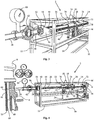
- Figures 1-7 show an injection module 2 according to the invention connected to a thin coiled tubing 4 coiled upon a separate coiled tubing spool 6 placed in immediate vicinity of the injection module 2.
- the spool 6 and the coiled tubing 4 may also be connected to a line (not shown) for allowing, at a later point in time, pumping of a treatment agent, for example a well killing fluid, via the coiled tubing 4 and into an underground well.
- a treatment agent for example a well killing fluid
- the injection module 2 and the coiled tubing spool 6 are placed beside a wellhead 8 on a wellhead deck 10 on an offshore platform.
- the injection module 2 and the coiled tubing spool 6 may just as well be placed beside a wellhead on a land-based well.
- the injection module 2 comprises a frame structure 12 provided, among other things, with various injection equipment for coiled tubing operations.
- this injection equipment in this embodiment comprise a heavy duty conveyor device 14 for the coiled tubing 4; a shear ram 16 connected to a respective inlet 18 and outlet 20 for hydraulic fluid for activation of the shear ram 16; and a stuffing box 22 connected to a flexible return hose 24.
- the stuffing box 22 contains at least one packer element which, by means of an associated piston device, is forced in a pressure-sealing manner around the coiled tubing 4 when being conducted through the stuffing box 22.
- Such injection equipment constitute prior art.
- FIG. 14 An example of a conveyor device resembling the present conveyor device 14, is described in detail in the above-mentioned US 5.188.174 .
- the stuffing box 22 Seen further in the insertion direction of the coiled tubing 4, the stuffing box 22 is connected in a pressure-sealing manner to an insertion device according to the invention.
- figures 1-7 show a lengthy and cylinder-shaped insertion device 26 through which the coiled tubing 4 may be conducted, as required.
- said conveyor device 14 contains two parallel and endless chains 28, 30, each of which is disposed in a rotatable manner around a respective set of chain sprocket wheels (not shown). Nearby and opposite sides of the chains 28, 30 are also arranged with some distance therebetween so as to allow them, when in their positions of use, to conduct the coiled tubing 4 between the opposite chain sides.
- each chain 28, 30 is provided with continuous, external gripping elements (nto shown) which, when in their positions of use, are forced against the coiled tubing 4 so as to grip it simultaneously with the chains 28, 30 rotating synchronously for conveyance of the coiled tubing 4.
- Driving devices and associated equipment for the purpose of forcing said gripping elements towards the coiled tubing 4, and for the purpose of rotating said chain sprocket wheels and thus the chains 28, 30, are not shown in the figures.
- driving devices may be comprised of rotary motors and hydraulic cylinders with associated pistons.
- the coiled tubing 4 may be conducted onwards through the shear ram 16, the stuffing box 22 and into the insertion device 26, which will be explained in further detail in the following.
- the conveyor device 14, the shear ram 16, the stuffing box 22 and the insertion device 26 are assembled in a coaxial manner for conducting the coiled tubing 4 along a mutual axis.
- said insertion device 26 comprises a first end portion 32 comprised of a cast bending head 34 according to a first embodiment thereof.
- a bending path 36 is formed within the bending head 34 during the casting thereof.
- the bending head 34 is structured in a manner allowing it to directionally deviate the coiled tubing 4 by ca. 90 degrees when conducted along the bending path 36.
- the insertion device 26 is also provided with a guide conduit in the form of a first bore 38 extending from a second end portion 40 of the insertion device 26 and onwards to the bending head 34. Thereby, the coiled tubing 4 may be conducted forward and be pushed into the bending head 34 by means of the conveyor device 14.
- the insertion device 26 is provided with a return flow conduit in the form of a second bore 42 extending between the first and second end portions 32, 40 of the insertion device 26.
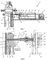
- the guide conduit 38 and the return flow conduit 42 are shown best in figure 6 .
- both the injection equipment for coiled tubing operations and the insertion device 26 are structured so as to be horizontally movable relative to the frame structure 12.
- the frame structure 12 is provided with a moving means comprising, among other things, two parallel and horizontal thread bars, i.e. a first thread bar 44 and a second thread bar 46, which are disposed at a distance from each other.
- the thread bars 44, 46 have threads of a self-locking type.
- the ends of the thread bars 44, 46 are supported in rotatable manner in respective sides of a first support plate 48 (closest to the spool 6) and a second support plate 50 (closest to the wellhead 8), respectively.
- the support plates 48, 50 are secured at either end of the frame structure 12.
- the thread bars 44, 46 are connected to at least one driving device (not shown), for example an electric or hydraulic rotary motor.
- the second support plate 50 is also provided with a respective centre hole 52 through which the insertion device 26 is conducted during use.
- the second support plate 50 is provided with a ring-shaped connector 54 disposed on the outside of the support plate 50 and around the centre hole 52 thereof.
- the connector 54 is used for pressure-tight connection of the injection module 2 to a coupling flange 56 on a horizontal pipe stub 58 provided with a pressure gauge 60 and a gate valve 62, and which is connected to a side bore 64 on the wellhead 8.
- the side bore 64 communicates with an annulus 66 between two sizes of casing, i.e. a first casing 68 and a second casing 70, in the wellhead 8.
- the moving means of the frame structure 12 also comprises a first, second and third moving plate 72, 74, 76 movably connected to the thread bars 44, 46 via corresponding threaded holes 78 also having self-locking threads, and which are disposed in respective sides of of each moving plate 72, 74, 76.
- the conveyor device 14 is attached between the first and second moving plate 72, 74, whereas the shear ram 16 and the stuffing box 22 are attached to the second and third moving plate 74, 76.
- These equipment components 14, 16, 22 with associated equipment are also disposed between the thread bars 44, 46. Upon appropriate rotatition of the thread bars 44, 46, these equipment components with associated equipment will therefore move horizontally relative to the frame structure 12, which is placed on the wellhead deck 10.
- the separate injection module 2 is connected to said horizontal pipe stub 58 on the wellhead 8, after which it is possible to carry out a lateral insertion and bending of the coiled tubing 4 via said side bore 64 in the wellhead 8.
- This connection is carried out by connecting, in a pressure-sealing manner, said connector 54 on the injection module 2 to the coupling flange 56 on the pipe stub 58, as shown in figures 2 and 3 .
- the gate valve 62 on the pipe stub 58 will be closed.
- the gate valve 62 is opened, after which the insertion device 26 is conducted through the centre hole 52 in the connector 54 and onwards through the pipe stub 58 and the side bore 64 until the bending head 34 is placed in the annulus 66 of the wellhead 8, as shown in figures 4-6 .
- the horizontal displacement of the insertion device 26, the stuffing box 22, the shear ram 16 and the conveyor device 14 in the direction of the wellhead 8, is carried out through appropriate rotation of the thread bars 44, 46 of the injection module 2, as explained above.
- the endless chains 28, 30 of the conveyor device 14 are activated and pushed the coiled tubing 4, which in advance has been conducted into the equipment components 14, 16, 22 and through the first bore 38 (the guide conduit) of the insertion device 26 and onwards via the bending path 36 of the bending head 34.
- the nose portion of the coiled tubing 4 has been prepared in advance for continued insertion in the annulus 66 once the injection module 2 has been connected to the side bore 64 in the wellhead 8.
- the coiled tubing 4 is directionally deviated by ca. 90 degrees so as to discharge from the bending head 34 facing downwards into the annulus 66, and substantially parallel to the casings 68, 70, as shown in figures 7 and 8 .
- the coiled tubing 4 is pushed further downward into the annulus 66 to a desired location in an associated well to which the wellhead 8 is connected.
- a suitable fluid for example a heavier well killing fluid, may be pumped through the coiled tubing 4 and down to this location in the annulus 66.
- the fluid already located in the annulus 66, and which is displaced by the fluid being pumped down into the annulus 66 via the coiled tubing 4 may flow out of this upper portion of the annulus 66 via said second bore 42 (the return flow conduit) in the insertion device 26.
- the coiled tubing 4 may be withdrawn from the annulus 66.
- the coiled tubing 4 may possibly be separated from the injection module 2. Then the separated coiled tubing 4 is connected to the side bore 64 of the wellhead 8. By so doing, the coiled tubing 4 is fixedly installed in the annulus 66 and is prepared for future well operations.
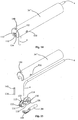
- FIGS. 9 and 10 show a cylinder-shaped bending head 34' according to a second embodiment thereof.
- This bending head 34' is disposed at the first end portion 32 of the insertion device 26 and is hydraulically connected to the second end portion 40 of the insertion device 26, for example via a lengthy connector.
- This bending head 34' comprises two cooperating profile parts, i.e. a first profile part 80 and a second profile part 82.
- the profile parts 80, 82 have complementarily shaped contact surfaces, i.e. a first contact surface 84 and a second contact surface 86, collectively defining a bending path 36' structured in a manner allowing it to directionally deviate the coiled tubing 4 by ca. 90 degrees.
- the first profile part 80 is comprised of a massive, circular cylinder provided with an external groove (only shown in part), the innermost part of which has a shape forming the first contact surface 84 defining one surface portion of the bending path 36'.
- This groove also comprises a longitudinal groove portion 84' on the upper side of the profile part 80, and a transverse groove portion 84" at the outer end of the profile part 80. Viewed in cross-section, the contact surface 84 forms a partial circle.
- the second profile part 82 is comprised of a slender angle profile fitting into said groove in the first profile part 80, and which internally has a shape forming the second contact surface 86. A mid-portion of this contact surface 86 defines the remaining, opposite surface portion of the bending path 36'.
- the inside of the angle profile 82 also comprises a longitudinal groove portion 86' and a transverse groove portion 86". Viewed in cross-section, the second contact surface 86 forms a partial circle fitting in a complementary manner together with the first contact surface 84 so as to collectively define the bending path 36'.
- the second profile part 82 is also formed with a longitudinal, arcuate strip 88 with peripheral, outwardly-directed flanks 90 fitting into corresponding recesses (not shown) in the external groove in the first profile part 80.
- the strip 88 and its flanks 90 will complement the external, circular shape of the first profile part 80.
- the bending head 34' may be readily conducted into said annulus 66 via the pipe stub 58 of the wellhead 8, as shown in figure 10 .
- FIG. 11-17 show a cylinder-shaped bending head 34" according to a third embodiment thereof. Also this bending head 34" is disposed at the first end portion 32 of the insertion device 26 and is hydraulically connected to the second end portion 40 of the insertion device 26, for example via a lengthy connector.
- the bending head 34" comprises, among other things, a front end within which a bending path 36" is formed. Also this bending path 36" is structured in a manner allowing it to directionally deviate the coiled tubing 4 by ca. 90 degrees.
- the bending head 34" also comprises a straight portion provided with a bore 92 (guide conduit) for the coiled tubing 4 and a hydraulics bore 94; cf. figures 12, 13 , 16 and 17 .
- the bore 92 continues onwards to the bending path 36"
- the hydraulics bore 94 continues onwards to a movable piston 96 disposed in hydraulic cylinder 98.
- the piston 96 is connected to a piston rod 100 conducted through a hole in a partition wall 102, and which is connected to a lengthy directional stabilizer 104 disposed directly at an outlet 106 from the bending head 34". These elements are shown best in figures 12 and 13 , which show longitudinal sections through the bending head 34".
- the directional stabilizer 104 is also provided with a rounded contact surface 108, which is to support the coiled tubing 4 laterally and hence directionally steer it when discharging from the bending head 34", as shown in figure 13 .
- the supportive force exerted by the directional stabilizer 104 on the coiled tubing 4 in this context, may be adjusted by means of the piston 96 and the hydraulic pressure supplied via the hydraulics bore 94.
- the bending head 34" also comprises a wheel frame 110 provided with two cooperating and rotatable wheels, i.e. a first wheel 112 and a somewhat larger, second wheel 114, and a transverse bolt 116 suspended in the wheel frame 110 at an outer end thereof.
- the wheels 112, 114 have complementarily shaped circumferences which, when assembled vis-à-vis each other, defines a lower portion of the bending path 36". Viewed in cross-section, each opposite wheel circumference thus forms a partial circle.
- the wheels 112, 114 are disposed with some distance therebetween so as to allow them to conduct the coiled tubing 4 therebetween, as shown in figure 13 .
- the first wheel 112 is rotatably arranged via a needle bearing 118 attached around a transverse axle 120 supported in two first holes 122 in the wheel frame 110.
- the second wheel 114 is rotatably arranged via a needle bearing 124 attached around a transverse axle 126 carried through two second holes 128 in the wheel frame 110 (cf. figures 11 , 15 and 17 ), and which are supported in two holes 130 in the very bending head 34" (cf. figures 14 and 16 , among other places). Supported in this manner, the first wheel 112 may be rotated somewhat around the transverse axle 126 attached to the very bending head 34".
- this construction may be used to adjust the pressure force exerted by the first wheel 112 on the coiled tubing 4 when being conducted through the bending path 36".
- said transverse bolt 116 at the outer end of the wheel frame 110 is provided with a threaded hole 132 through which a threaded bolt 134 is screwed.
- the threaded bolt 134 is carried through a passage 136 in the front and upper end of the bending head 34". This passage 136 continues up to a shoulder 138 in a recess 140 at the top of the bending head 34".
- a bolt head 142 of the threaded bolt 134 is supported on this shoulder 138.
- the first wheel 112 may be rotated in the desired direction around the transverse axel 126 supported in the bending head 34". By so doing, the first wheel 112 may be raised or lowered relative to the coiled tubing 4 when conducted between the wheels 112 and 114, as shown in figure 13 . By so doing, also said pressure force on the coiled tubing 4 may be adjusted suitably. The pressure force on the coiled tubing 4 will increase when the first wheel 112 is lowered, whereas the pressure force will be reduced upon raising the wheel 112.
- This raising- and lowering function of the first wheel 112 may also be achieved by connecting the transverse bolt 116 in the wheel frame 110 to a piston (not shown) connected to a hydraulic, pneumatic or electric driving device (not shown) placed in the bending head 34".
- a driving device may possibly be structured for remote activation and control.
- the bending head 34" may also be provided with various meters, electronics, etc. for feedback and control of the driving device and the position of the first wheel 112 in the bending head 34" and with respect to the coiled tubing 4.
- a return flow of a fluid from the annulus 66 may be conducted via a potential return flow conduit (not shown) arranged in the bending head 34" between the bore 92 for the coiled tubing 4 and the hydraulics bore 94.
- a return flow conduit may also be in flow communication with a corresponding return flow conduit arranged in the remaining part of the insertion device 26.
Landscapes
- Engineering & Computer Science (AREA)
- Geology (AREA)
- Mining & Mineral Resources (AREA)
- Life Sciences & Earth Sciences (AREA)
- General Life Sciences & Earth Sciences (AREA)
- Environmental & Geological Engineering (AREA)
- Physics & Mathematics (AREA)
- Geochemistry & Mineralogy (AREA)
- Fluid Mechanics (AREA)
- Mechanical Engineering (AREA)
- Consolidation Of Soil By Introduction Of Solidifying Substances Into Soil (AREA)
- Bending Of Plates, Rods, And Pipes (AREA)
- Earth Drilling (AREA)
- Guides For Winding Or Rewinding, Or Guides For Filamentary Materials (AREA)
- Rigid Pipes And Flexible Pipes (AREA)
- Working Measures On Existing Buildindgs (AREA)
- Infusion, Injection, And Reservoir Apparatuses (AREA)
- Shaping Of Tube Ends By Bending Or Straightening (AREA)
- Magnetic Resonance Imaging Apparatus (AREA)
Claims (12)
- Injektionsmodul (2) zum seitlichen Einführen und Biegen eines gewundenen Rohres (4) über eine Seitenöffnung (64) in einen Brunnen, wobei das Modul (2) für eine Verbindung mit der Seitenöffnung (64) aufgebaut ist und wobei das Modul (2) Injektionsausrüstung (14, 16, 18, 20, 22) für den Betrieb des gewundenen Rohres umfasst,
wobei:das Modul (2) auch eine Einführungsvorrichtung (26) umfasst, die mit der Injektionsausrüstung (14, 16, 18, 20, 22) verbunden ist;die Einführungsvorrichtung (26) ist in einer Weise aufgebaut, die es ermöglicht, dass sie in die Seitenöffnung (64) im Brunnen passt;ein erster Endteil (32) der Einführungsvorrichtung (26) umfasst einen Biegekopf (34; 34'; 34") mit einem Biegeweg (36; 36'; 36"), wobei der Biegekopf (34; 34'; 34") s aufgebaut ist, dass er das gewundene Rohr (4) beim Führen des gewundenen Rohres (4) entlang des Biegeweges (36; 36'; 36") gerichtet ablenkt;die Einführungsvorrichtung (26) ist mit einem Führungskanal (38) versehen, der sich von einem zweiten Endteil (40) der Einführungsvorrichtung (26) und weiter zum Biegekopf (34; 34'; 34") erstreckt, um dem gewundenen Rohr (4) zu ermöglichen, in den Biegekopf (34; 34'; 34") eingeführt zu werden;die Einführungsvorrichtung (26) ist mit einem Bewegungsmittel (44, 46, 72, 74, 76) verbunden, das auf dem Injektionsmodul angeordnet ist; unddas Bewegungsmittel (44, 46, 72, 74, 76) ist so aufgebaut, dass es ermöglicht, die Einführungsvorrichtung (26) gegenüber dem Injektionsmodul (2) nach der Verbindung desselben mit der Seitenöffnung (64) im Brunnen zu bewegen. - Injektionsmodul (2) nach Anspruch 1, wobei der Führungskanal (38) aus einer Bohrung in der Einführungsvorrichtung (26) besteht.
- Injektionsmodul (2) nach Anspruch 1 oder 2, wobei der Biegeweg (36) durch Gießen des Biegekopfes (34) gebildet wird.
- Injektionsmodul (2) nach Anspruch 1 oder 2, wobei der Biegekopf (34') mindestens zwei zusammenwirkende Profilteile (80, 82) umfasst, die komplementär geformte Kontaktflächen (84, 86) haben, die zusammen den Biegeweg (36') definieren.
- Injektionsmodul (2) nach Anspruch 1 oder 2, wobei der Biegekopf (34") mindestens zwei zusammenwirkende Räder (112, 114) umfasst, die zusammen mindestens einen Teil des Biegeweges (36") definieren, wobei die zusammenwirkenden Räder (112, 114) so aufgebaut sind, dass es ihnen möglich wird, das gewundene Rohr (4) entlang des Biegeweges (36") beim Führen des gewundenen Rohres (4) zwischen den Rädern (112, 114) richtungsmäßig abzulenken.
- Injektionsmodul (2) nach Anspruch 5, wobei die Einführungsvorrichtung (26) einen Richtungsstabilisator (104) umfasst, der an einem Auslass (106) aus dem Biegekopf (34; 34'; 34") zur Richtungssteuerung des gewundenen Rohres (4) nach dem Auslass (106) angeordnet ist.
- Injektionsmodul (2) nach einem der Ansprüche 1-6, wobei die Einführungsvorrichtung (26) mit einem Rücklaufrohr (42) für den Rücklauf eines Fluids aus dem Brunnen versehen ist.
- Verfahren zur seitlichen Einführung und Biegung eines gewundenen Rohres (4) über eine Seitenöffnung (64) in einem Brunnen, wobei das Verfahren die folgenden Schritte umfasst:(A) Verwenden eines separaten Injektionsmoduls (2), das Injektionsausrüstung (14, 16, 18, 20, 22) für Arbeiten an einem gewundenen Rohr umfasst;und gekennzeichnet durch:(B) Verwenden einer Einführungsvorrichtung (26), die mit der Injektionsausrüstung (14, 16, 18, 20, 22) verbunden ist, und Verbinden der Einführungsvorrichtung (26) mit einem Bewegungsmittel (44, 46, 72, 74, 76), das auf dem Injektionsmodul (2) angeordnet ist, wobei die Einführungsvorrichtung (26) die folgenden Merkmale umfasst:- einen ersten Endteil (32), der einen Biegekopf (34; 34'; 34") mit einem Biegeweg (36; 36'; 36") umfasst; und- ein Führungsrohr (38), das sich von einem zweiten Endteil (40) der Einführungsvorrichtung (26) aus erstreckt und weiter zum Biegekopf (34; 34'; 34");(C) Verbinden des Injektionsmoduls (2) mit der Seitenöffnung (64) im Brunnen, und nachdem das Injektionsmodul (2) mit der Seitenöffnung (64) des Brunnens verbunden wurde, Führen der Einführungsvorrichtung (26) in die Seitenöffnung (64) mit dem Bewegungsmittel (44, 46, 72, 74, 76);(D) Führen des gewundenen Rohres (4) in den Brunnen über die Einführungsvorrichtung (26) und ihr Führungsrohr (38) und den Biegeweg (36; 36'; 36") im Biegekopf (34; 34'; 34"), um so das gewundene Rohr (4) richtungsmäßig abzulenken; und(E) Führen des gewundenen Rohres (4) vorwärts in den Brunnen zu einer gewünschten Stelle.
- Verfahren nach Anspruch 8, wobei das Verfahren, nach Schritt (E), auch einen Schritt (F) des Führens eines Fluids durch das gewundene Rohr (4) und weiter zur gewünschten Stelle im Brunnen umfasst.
- Verfahren nach Anspruch 9, das das Führen eines Rückflusses eines Fluids aus dem Brunnen über eine separate Auslassöffnung im Brunnen umfasst.
- Verfahren nach Anspruch 9, wobei das Verfahren auf Folgendes umfasst:- in Schritt (B), die Einführungsvorrichtung (26), die ferner ein Rücklaufrohr (42) umfasst; und- in Schritt (F), Ermöglichen, dass ein Rückfluss eines Fluids aus dem Brunnen über das Rücklaufrohr (42) ausfließt.
- Verfahren nach einem der Ansprüche 8-11, wobei das Verfahren auch Folgendes umfasst:- nach Schritt (E), Trennen des gewundenen Rohres (4) vom Injektionsmodul (2); und- Verbinden des abgetrennten gewundenen Rohres (4) mit der Seitenöffnung (64) des Brunnens, wodurch das gewundene Rohr (4) fest im Brunnen installiert wird.
Priority Applications (1)
| Application Number | Priority Date | Filing Date | Title |
|---|---|---|---|
| PL10836257T PL2510185T3 (pl) | 2009-12-07 | 2010-12-06 | Wtryskowy moduł, sposób i zastosowanie do bocznego wprowadzania i zginania nawiniętego przewodu rurowego za pośrednictwem bocznego otworu w odwiercie |
Applications Claiming Priority (2)
| Application Number | Priority Date | Filing Date | Title |
|---|---|---|---|
| NO20093484A NO332472B1 (no) | 2009-12-07 | 2009-12-07 | Injeksjonsmodul, fremgangsmåte og anvendelse for sideveis innføring og bøyning av et kveilrør via en sideåpning i en brønn |
| PCT/NO2010/000447 WO2011071389A1 (en) | 2009-12-07 | 2010-12-06 | Injection module, method and use for lateral insertion and bending of a coiled tubing via a side opening in a well |
Publications (3)
| Publication Number | Publication Date |
|---|---|
| EP2510185A1 EP2510185A1 (de) | 2012-10-17 |
| EP2510185A4 EP2510185A4 (de) | 2015-10-14 |
| EP2510185B1 true EP2510185B1 (de) | 2017-06-14 |
Family
ID=44145759
Family Applications (1)
| Application Number | Title | Priority Date | Filing Date |
|---|---|---|---|
| EP10836257.5A Active EP2510185B1 (de) | 2009-12-07 | 2010-12-06 | Einspritzmodul, verfahren dafür und seine anwendung für seitlichen einsatz und zum biegen eines gespulten schlauchs entlang einer seitlichen bohrlochöffnung |
Country Status (10)
| Country | Link |
|---|---|
| US (1) | US9045954B2 (de) |
| EP (1) | EP2510185B1 (de) |
| AU (1) | AU2010328737B2 (de) |
| CA (1) | CA2782360C (de) |
| DK (1) | DK2510185T3 (de) |
| EA (1) | EA201290479A1 (de) |
| MY (1) | MY159900A (de) |
| NO (1) | NO332472B1 (de) |
| PL (1) | PL2510185T3 (de) |
| WO (1) | WO2011071389A1 (de) |
Families Citing this family (6)
| Publication number | Priority date | Publication date | Assignee | Title |
|---|---|---|---|---|
| GB201220671D0 (en) | 2012-11-16 | 2013-01-02 | Quality Intervention As | Apparatus and method for bending coiled tubing |
| GB2546556B (en) * | 2016-01-25 | 2021-04-14 | Quality Intervention Tech As | Well access tool |
| GB2559989B (en) | 2017-02-23 | 2021-10-13 | Quality Intervention Tech As | Well access apparatus and method |
| WO2021042205A1 (en) * | 2019-09-04 | 2021-03-11 | Inter-Casing Pressure Control Inc. | Inter-casing pressure control systems and methods |
| US11512550B2 (en) | 2019-11-22 | 2022-11-29 | Conocophillips Company | Delivering fluid to a subsea wellhead |
| WO2025184308A1 (en) * | 2024-02-27 | 2025-09-04 | Saudi Arabian Oil Company | Closed compartment well tool for wellhead re-packing |
Family Cites Families (35)
| Publication number | Priority date | Publication date | Assignee | Title |
|---|---|---|---|---|
| US2548616A (en) * | 1948-02-02 | 1951-04-10 | Priestman George Dawson | Well drilling |
| US4388969A (en) * | 1980-12-01 | 1983-06-21 | Nl Industries, Inc. | Borehole pipe side entry method and apparatus |
| US4848480A (en) * | 1986-10-15 | 1989-07-18 | Comdisco Resources, Inc. | Method and apparatus for wire line protection in a well |
| US4972904A (en) * | 1989-08-24 | 1990-11-27 | Foster Oilfield Equipment Co. | Geothermal well chemical injection system |
| FR2652857B1 (fr) * | 1989-10-11 | 1993-06-04 | Inst Francais Du Petrole | Dispositif de blocage pour un cable traversant la paroi d'un tube tel qu'un raccord a fenetre laterale. |
| CA2037240C (en) * | 1991-02-27 | 1997-09-30 | Leon Jantzen | Guide arch for tubing |
| US5188174A (en) * | 1991-04-03 | 1993-02-23 | Stewart & Stevenson Services, Inc. | Apparatus for inserting and withdrawing coil tubing into a well |
| US5469925A (en) * | 1993-10-06 | 1995-11-28 | Union Oil Company Of California | Downhole tube turning tool |
| US5775417A (en) * | 1997-03-24 | 1998-07-07 | Council; Malcolm N. | Coiled tubing handling apparatus |
| US6289992B1 (en) * | 1997-06-13 | 2001-09-18 | Abb Vetco Gray, Inc. | Variable pressure pump through nozzle |
| US5927405A (en) * | 1997-06-13 | 1999-07-27 | Abb Vetco Gray, Inc. | Casing annulus remediation system |
| US6047776A (en) * | 1998-01-15 | 2000-04-11 | Abb Vetco Gray Inc. | Enhanced control line exit |
| US6186239B1 (en) * | 1998-05-13 | 2001-02-13 | Abb Vetco Gray Inc. | Casing annulus remediation system |
| CA2268223C (en) * | 1999-04-01 | 2000-02-15 | Lenard Alfred Jack | A method of cleaning a well that is contaminated by accumulations of sa nd |
| CA2298089A1 (en) * | 2000-02-03 | 2001-08-03 | Plains Energy Services Ltd. | Linear coiled tubing injector |
| CN1451075A (zh) * | 2000-05-16 | 2003-10-22 | 奥梅加石油公司 | 用于采收地下碳氢化合物的方法和装置 |
| US6457530B1 (en) * | 2001-03-23 | 2002-10-01 | Stream-Flo Industries, Ltd. | Wellhead production pumping tree |
| US6851478B2 (en) * | 2003-02-07 | 2005-02-08 | Stream-Flo Industries, Ltd. | Y-body Christmas tree for use with coil tubing |
| CA2423645A1 (en) * | 2003-03-28 | 2004-09-28 | Larry Bunney | Manifold device and method of use for accessing a casing annulus of a well |
| US7069995B2 (en) | 2003-04-16 | 2006-07-04 | Vetco Gray Inc. | Remedial system to flush contaminants from tubing string |
| GB0326868D0 (en) * | 2003-11-18 | 2003-12-24 | Wood Group Logging Services In | Fiber optic deployment apparatus and method |
| BRPI0516551B1 (pt) * | 2004-10-07 | 2017-05-02 | Bj Services Co | válvula e método para comunicação com uma zona abaixo de uma válvula |
| US20070000670A1 (en) * | 2005-03-31 | 2007-01-04 | Moore John D | Method and apparatus for installing strings of coiled tubing |
| BRPI0612054A2 (pt) * | 2005-06-08 | 2010-10-13 | Bj Services Co | método e aparelho de desvio de cabeça de poço |
| US7721798B2 (en) * | 2005-07-19 | 2010-05-25 | Tesco Corporation | Wireline entry sub |
| US7699099B2 (en) * | 2006-08-02 | 2010-04-20 | B.J. Services Company, U.S.A. | Modified Christmas tree components and associated methods for using coiled tubing in a well |
| GB2460329B (en) * | 2008-05-20 | 2013-03-27 | Vetco Gray Inc | Varying access points for tubing and casing monitoring and casing annulus remediation systems |
| US8327934B2 (en) * | 2008-07-03 | 2012-12-11 | Vetco Gray Inc. | Acoustically measuring annulus probe depth |
| US7762327B2 (en) * | 2008-07-03 | 2010-07-27 | Vetco Gray Inc. | Acoustically measuring annulus probe depth |
| US7686091B2 (en) | 2008-07-28 | 2010-03-30 | Vetco Gray Inc. | Device to insert a flexible member into pressurized wellhead housing |
| US8181700B2 (en) * | 2009-06-22 | 2012-05-22 | Vetco Gray Inc. | System and method of displacing fluids in an annulus |
| CA2770179A1 (en) * | 2009-08-06 | 2011-02-10 | Millennium Oilflow Systems & Technology Inc. | Stuffing box assembly |
| US8230934B2 (en) * | 2009-10-02 | 2012-07-31 | Baker Hughes Incorporated | Apparatus and method for directionally disposing a flexible member in a pressurized conduit |
| US8403039B2 (en) * | 2010-05-13 | 2013-03-26 | Vetco Gray Inc. | Tool and method for providing access to a wellhead annulus |
| GB201101467D0 (en) * | 2011-01-28 | 2011-03-16 | Cameron Int Corp | Tool |
-
2009
- 2009-12-07 NO NO20093484A patent/NO332472B1/no unknown
-
2010
- 2010-12-06 EP EP10836257.5A patent/EP2510185B1/de active Active
- 2010-12-06 WO PCT/NO2010/000447 patent/WO2011071389A1/en not_active Ceased
- 2010-12-06 MY MYPI2012002484A patent/MY159900A/en unknown
- 2010-12-06 PL PL10836257T patent/PL2510185T3/pl unknown
- 2010-12-06 AU AU2010328737A patent/AU2010328737B2/en active Active
- 2010-12-06 US US13/513,250 patent/US9045954B2/en active Active
- 2010-12-06 CA CA2782360A patent/CA2782360C/en active Active
- 2010-12-06 EA EA201290479A patent/EA201290479A1/ru unknown
- 2010-12-06 DK DK10836257.5T patent/DK2510185T3/en active
Also Published As
| Publication number | Publication date |
|---|---|
| MY159900A (en) | 2017-02-15 |
| US9045954B2 (en) | 2015-06-02 |
| EA201290479A1 (ru) | 2013-01-30 |
| DK2510185T3 (en) | 2017-09-18 |
| AU2010328737A1 (en) | 2012-08-02 |
| NO332472B1 (no) | 2012-09-24 |
| NO20093484A1 (no) | 2011-06-08 |
| PL2510185T3 (pl) | 2017-11-30 |
| EP2510185A4 (de) | 2015-10-14 |
| AU2010328737B2 (en) | 2014-10-23 |
| WO2011071389A1 (en) | 2011-06-16 |
| EP2510185A1 (de) | 2012-10-17 |
| US20120241174A1 (en) | 2012-09-27 |
| CA2782360A1 (en) | 2011-06-16 |
| CA2782360C (en) | 2017-05-30 |
Similar Documents
| Publication | Publication Date | Title |
|---|---|---|
| EP2510185B1 (de) | Einspritzmodul, verfahren dafür und seine anwendung für seitlichen einsatz und zum biegen eines gespulten schlauchs entlang einer seitlichen bohrlochöffnung | |
| US7438126B2 (en) | Apparatus for controlling a tool having a mandrel that must be stroked into or out of a well | |
| US4867243A (en) | Wellhead isolation tool and setting and method of using same | |
| US8925651B2 (en) | Hydraulic drilling method with penetration control | |
| AU2018208661A1 (en) | Subsea Slanted Wellhead System and BOP System with Dual Injector Head Units | |
| EP1438480B1 (de) | Verfahren zur bohrloch-flüssigkeitsbehandlung und pumpengestänge dafür | |
| WO2008109280A1 (en) | Subsea adapter for connecting a riser to a subsea tree | |
| WO2003069112A1 (en) | Wellhead seal unit | |
| US7832480B1 (en) | Apparatus and method for extracting a tubular string from a bore hole | |
| EP1076756B1 (de) | Vorrichtung, system und verfahren zum verbinden einer vorrichtung, mit wickelrohren | |
| WO2009098473A2 (en) | Hydraulic connector apparatuses and methods of use with downhole tubulars | |
| US20150090461A1 (en) | Detachable capping device and method for an oil/gas well under blowout conditions | |
| US12560044B2 (en) | Lock sequencing system for a blowout preventer | |
| CN107002478B (zh) | 一种用于提取井的安全阀及用来关闭井的方法 | |
| EP3803035B1 (de) | Modularer kopf für bohrlochrohre | |
| US10954738B2 (en) | Dual compact cutting device intervention system | |
| EP2751386B1 (de) | Umlenkerspule und verwendungsverfahren dafür | |
| WO2005012685A1 (en) | Drilling method | |
| US11965129B1 (en) | Method and system for mitigating downhole water production | |
| US20070227742A1 (en) | Casing transition nipple and method of casing a well to facilitate well completion, re-completion and workover | |
| Hadzihafizovic | Coiled Tubing Equipment | |
| CA2452457C (en) | Apparatus for controlling a tool having a mandrel that must be stroked into or out of a well | |
| CN120211659A (zh) | 连续油管速度管柱井口装置及其使用方法 | |
| CA2541748A1 (en) | A casing transition nipple and method of casing a well to facilitate well completion, re-completion and workover |
Legal Events
| Date | Code | Title | Description |
|---|---|---|---|
| PUAI | Public reference made under article 153(3) epc to a published international application that has entered the european phase |
Free format text: ORIGINAL CODE: 0009012 |
|
| 17P | Request for examination filed |
Effective date: 20120529 |
|
| AK | Designated contracting states |
Kind code of ref document: A1 Designated state(s): AL AT BE BG CH CY CZ DE DK EE ES FI FR GB GR HR HU IE IS IT LI LT LU LV MC MK MT NL NO PL PT RO RS SE SI SK SM TR |
|
| DAX | Request for extension of the european patent (deleted) | ||
| RA4 | Supplementary search report drawn up and despatched (corrected) |
Effective date: 20150916 |
|
| RIC1 | Information provided on ipc code assigned before grant |
Ipc: E21B 33/068 20060101AFI20150910BHEP Ipc: E21B 19/22 20060101ALI20150910BHEP |
|
| 17Q | First examination report despatched |
Effective date: 20160502 |
|
| GRAP | Despatch of communication of intention to grant a patent |
Free format text: ORIGINAL CODE: EPIDOSNIGR1 |
|
| INTG | Intention to grant announced |
Effective date: 20170102 |
|
| GRAS | Grant fee paid |
Free format text: ORIGINAL CODE: EPIDOSNIGR3 |
|
| GRAA | (expected) grant |
Free format text: ORIGINAL CODE: 0009210 |
|
| AK | Designated contracting states |
Kind code of ref document: B1 Designated state(s): AL AT BE BG CH CY CZ DE DK EE ES FI FR GB GR HR HU IE IS IT LI LT LU LV MC MK MT NL NO PL PT RO RS SE SI SK SM TR |
|
| REG | Reference to a national code |
Ref country code: GB Ref legal event code: FG4D |
|
| REG | Reference to a national code |
Ref country code: CH Ref legal event code: EP Ref country code: AT Ref legal event code: REF Ref document number: 901149 Country of ref document: AT Kind code of ref document: T Effective date: 20170615 |
|
| REG | Reference to a national code |
Ref country code: IE Ref legal event code: FG4D |
|
| REG | Reference to a national code |
Ref country code: DE Ref legal event code: R096 Ref document number: 602010043033 Country of ref document: DE |
|
| REG | Reference to a national code |
Ref country code: RO Ref legal event code: EPE |
|
| REG | Reference to a national code |
Ref country code: DK Ref legal event code: T3 Effective date: 20170914 |
|
| REG | Reference to a national code |
Ref country code: NL Ref legal event code: FP |
|
| REG | Reference to a national code |
Ref country code: NO Ref legal event code: T2 Effective date: 20170614 |
|
| REG | Reference to a national code |
Ref country code: LT Ref legal event code: MG4D |
|
| PG25 | Lapsed in a contracting state [announced via postgrant information from national office to epo] |
Ref country code: HR Free format text: LAPSE BECAUSE OF FAILURE TO SUBMIT A TRANSLATION OF THE DESCRIPTION OR TO PAY THE FEE WITHIN THE PRESCRIBED TIME-LIMIT Effective date: 20170614 Ref country code: ES Free format text: LAPSE BECAUSE OF FAILURE TO SUBMIT A TRANSLATION OF THE DESCRIPTION OR TO PAY THE FEE WITHIN THE PRESCRIBED TIME-LIMIT Effective date: 20170614 Ref country code: FI Free format text: LAPSE BECAUSE OF FAILURE TO SUBMIT A TRANSLATION OF THE DESCRIPTION OR TO PAY THE FEE WITHIN THE PRESCRIBED TIME-LIMIT Effective date: 20170614 Ref country code: GR Free format text: LAPSE BECAUSE OF FAILURE TO SUBMIT A TRANSLATION OF THE DESCRIPTION OR TO PAY THE FEE WITHIN THE PRESCRIBED TIME-LIMIT Effective date: 20170915 Ref country code: LT Free format text: LAPSE BECAUSE OF FAILURE TO SUBMIT A TRANSLATION OF THE DESCRIPTION OR TO PAY THE FEE WITHIN THE PRESCRIBED TIME-LIMIT Effective date: 20170614 |
|
| REG | Reference to a national code |
Ref country code: AT Ref legal event code: MK05 Ref document number: 901149 Country of ref document: AT Kind code of ref document: T Effective date: 20170614 |
|
| PG25 | Lapsed in a contracting state [announced via postgrant information from national office to epo] |
Ref country code: BG Free format text: LAPSE BECAUSE OF FAILURE TO SUBMIT A TRANSLATION OF THE DESCRIPTION OR TO PAY THE FEE WITHIN THE PRESCRIBED TIME-LIMIT Effective date: 20170914 Ref country code: SE Free format text: LAPSE BECAUSE OF FAILURE TO SUBMIT A TRANSLATION OF THE DESCRIPTION OR TO PAY THE FEE WITHIN THE PRESCRIBED TIME-LIMIT Effective date: 20170614 Ref country code: RS Free format text: LAPSE BECAUSE OF FAILURE TO SUBMIT A TRANSLATION OF THE DESCRIPTION OR TO PAY THE FEE WITHIN THE PRESCRIBED TIME-LIMIT Effective date: 20170614 Ref country code: LV Free format text: LAPSE BECAUSE OF FAILURE TO SUBMIT A TRANSLATION OF THE DESCRIPTION OR TO PAY THE FEE WITHIN THE PRESCRIBED TIME-LIMIT Effective date: 20170614 |
|
| PG25 | Lapsed in a contracting state [announced via postgrant information from national office to epo] |
Ref country code: AT Free format text: LAPSE BECAUSE OF FAILURE TO SUBMIT A TRANSLATION OF THE DESCRIPTION OR TO PAY THE FEE WITHIN THE PRESCRIBED TIME-LIMIT Effective date: 20170614 Ref country code: SK Free format text: LAPSE BECAUSE OF FAILURE TO SUBMIT A TRANSLATION OF THE DESCRIPTION OR TO PAY THE FEE WITHIN THE PRESCRIBED TIME-LIMIT Effective date: 20170614 Ref country code: EE Free format text: LAPSE BECAUSE OF FAILURE TO SUBMIT A TRANSLATION OF THE DESCRIPTION OR TO PAY THE FEE WITHIN THE PRESCRIBED TIME-LIMIT Effective date: 20170614 Ref country code: CZ Free format text: LAPSE BECAUSE OF FAILURE TO SUBMIT A TRANSLATION OF THE DESCRIPTION OR TO PAY THE FEE WITHIN THE PRESCRIBED TIME-LIMIT Effective date: 20170614 |
|
| PG25 | Lapsed in a contracting state [announced via postgrant information from national office to epo] |
Ref country code: SM Free format text: LAPSE BECAUSE OF FAILURE TO SUBMIT A TRANSLATION OF THE DESCRIPTION OR TO PAY THE FEE WITHIN THE PRESCRIBED TIME-LIMIT Effective date: 20170614 Ref country code: IS Free format text: LAPSE BECAUSE OF FAILURE TO SUBMIT A TRANSLATION OF THE DESCRIPTION OR TO PAY THE FEE WITHIN THE PRESCRIBED TIME-LIMIT Effective date: 20171014 |
|
| REG | Reference to a national code |
Ref country code: DE Ref legal event code: R097 Ref document number: 602010043033 Country of ref document: DE |
|
| PLBE | No opposition filed within time limit |
Free format text: ORIGINAL CODE: 0009261 |
|
| STAA | Information on the status of an ep patent application or granted ep patent |
Free format text: STATUS: NO OPPOSITION FILED WITHIN TIME LIMIT |
|
| 26N | No opposition filed |
Effective date: 20180315 |
|
| REG | Reference to a national code |
Ref country code: CH Ref legal event code: PL |
|
| PG25 | Lapsed in a contracting state [announced via postgrant information from national office to epo] |
Ref country code: SI Free format text: LAPSE BECAUSE OF FAILURE TO SUBMIT A TRANSLATION OF THE DESCRIPTION OR TO PAY THE FEE WITHIN THE PRESCRIBED TIME-LIMIT Effective date: 20170614 |
|
| REG | Reference to a national code |
Ref country code: IE Ref legal event code: MM4A |
|
| PG25 | Lapsed in a contracting state [announced via postgrant information from national office to epo] |
Ref country code: LU Free format text: LAPSE BECAUSE OF NON-PAYMENT OF DUE FEES Effective date: 20171206 Ref country code: MT Free format text: LAPSE BECAUSE OF NON-PAYMENT OF DUE FEES Effective date: 20171206 |
|
| REG | Reference to a national code |
Ref country code: FR Ref legal event code: ST Effective date: 20180831 |
|
| REG | Reference to a national code |
Ref country code: BE Ref legal event code: MM Effective date: 20171231 |
|
| PG25 | Lapsed in a contracting state [announced via postgrant information from national office to epo] |
Ref country code: FR Free format text: LAPSE BECAUSE OF NON-PAYMENT OF DUE FEES Effective date: 20180102 Ref country code: IE Free format text: LAPSE BECAUSE OF NON-PAYMENT OF DUE FEES Effective date: 20171206 |
|
| PG25 | Lapsed in a contracting state [announced via postgrant information from national office to epo] |
Ref country code: LI Free format text: LAPSE BECAUSE OF NON-PAYMENT OF DUE FEES Effective date: 20171231 Ref country code: CH Free format text: LAPSE BECAUSE OF NON-PAYMENT OF DUE FEES Effective date: 20171231 Ref country code: BE Free format text: LAPSE BECAUSE OF NON-PAYMENT OF DUE FEES Effective date: 20171231 |
|
| PGFP | Annual fee paid to national office [announced via postgrant information from national office to epo] |
Ref country code: DE Payment date: 20181015 Year of fee payment: 9 |
|
| REG | Reference to a national code |
Ref country code: DE Ref legal event code: R081 Ref document number: 602010043033 Country of ref document: DE Owner name: ANNULUS INTERVENTION SYSTEM AS, NO Free format text: FORMER OWNER: QUALITY INTERVENTION AS, BALESTRAND, NO |
|
| REG | Reference to a national code |
Ref country code: NO Ref legal event code: CHAD Owner name: ANNULUS INTERVENTION SYSTEM AS, NO Ref country code: NO Ref legal event code: CREP Representative=s name: PLOUGMANN VINGTOFT, POSTBOKS 1003 SENTRUM, 0104 |
|
| REG | Reference to a national code |
Ref country code: NL Ref legal event code: PD Owner name: ANNULUS INTERVENTION SYSTEM AS; NO Free format text: DETAILS ASSIGNMENT: CHANGE OF OWNER(S), DEMERGER; FORMER OWNER NAME: QUALITY INTERVENTION AS Effective date: 20190611 |
|
| PG25 | Lapsed in a contracting state [announced via postgrant information from national office to epo] |
Ref country code: MC Free format text: LAPSE BECAUSE OF FAILURE TO SUBMIT A TRANSLATION OF THE DESCRIPTION OR TO PAY THE FEE WITHIN THE PRESCRIBED TIME-LIMIT Effective date: 20170614 Ref country code: HU Free format text: LAPSE BECAUSE OF FAILURE TO SUBMIT A TRANSLATION OF THE DESCRIPTION OR TO PAY THE FEE WITHIN THE PRESCRIBED TIME-LIMIT; INVALID AB INITIO Effective date: 20101206 |
|
| PG25 | Lapsed in a contracting state [announced via postgrant information from national office to epo] |
Ref country code: CY Free format text: LAPSE BECAUSE OF NON-PAYMENT OF DUE FEES Effective date: 20170614 |
|
| PG25 | Lapsed in a contracting state [announced via postgrant information from national office to epo] |
Ref country code: MK Free format text: LAPSE BECAUSE OF FAILURE TO SUBMIT A TRANSLATION OF THE DESCRIPTION OR TO PAY THE FEE WITHIN THE PRESCRIBED TIME-LIMIT Effective date: 20170614 |
|
| PG25 | Lapsed in a contracting state [announced via postgrant information from national office to epo] |
Ref country code: TR Free format text: LAPSE BECAUSE OF FAILURE TO SUBMIT A TRANSLATION OF THE DESCRIPTION OR TO PAY THE FEE WITHIN THE PRESCRIBED TIME-LIMIT Effective date: 20170614 |
|
| PG25 | Lapsed in a contracting state [announced via postgrant information from national office to epo] |
Ref country code: PT Free format text: LAPSE BECAUSE OF FAILURE TO SUBMIT A TRANSLATION OF THE DESCRIPTION OR TO PAY THE FEE WITHIN THE PRESCRIBED TIME-LIMIT Effective date: 20170614 |
|
| REG | Reference to a national code |
Ref country code: DE Ref legal event code: R119 Ref document number: 602010043033 Country of ref document: DE |
|
| PG25 | Lapsed in a contracting state [announced via postgrant information from national office to epo] |
Ref country code: AL Free format text: LAPSE BECAUSE OF FAILURE TO SUBMIT A TRANSLATION OF THE DESCRIPTION OR TO PAY THE FEE WITHIN THE PRESCRIBED TIME-LIMIT Effective date: 20170614 |
|
| PG25 | Lapsed in a contracting state [announced via postgrant information from national office to epo] |
Ref country code: DE Free format text: LAPSE BECAUSE OF NON-PAYMENT OF DUE FEES Effective date: 20200701 |
|
| PGFP | Annual fee paid to national office [announced via postgrant information from national office to epo] |
Ref country code: DK Payment date: 20211227 Year of fee payment: 12 Ref country code: RO Payment date: 20211123 Year of fee payment: 12 |
|
| PGFP | Annual fee paid to national office [announced via postgrant information from national office to epo] |
Ref country code: IT Payment date: 20211221 Year of fee payment: 12 |
|
| PGFP | Annual fee paid to national office [announced via postgrant information from national office to epo] |
Ref country code: PL Payment date: 20211119 Year of fee payment: 12 |
|
| P01 | Opt-out of the competence of the unified patent court (upc) registered |
Effective date: 20230512 |
|
| REG | Reference to a national code |
Ref country code: DK Ref legal event code: EBP Effective date: 20221231 |
|
| PG25 | Lapsed in a contracting state [announced via postgrant information from national office to epo] |
Ref country code: RO Free format text: LAPSE BECAUSE OF NON-PAYMENT OF DUE FEES Effective date: 20221206 |
|
| PG25 | Lapsed in a contracting state [announced via postgrant information from national office to epo] |
Ref country code: IT Free format text: LAPSE BECAUSE OF NON-PAYMENT OF DUE FEES Effective date: 20221206 Ref country code: DK Free format text: LAPSE BECAUSE OF NON-PAYMENT OF DUE FEES Effective date: 20221231 |
|
| PGFP | Annual fee paid to national office [announced via postgrant information from national office to epo] |
Ref country code: NL Payment date: 20241004 Year of fee payment: 15 |
|
| PG25 | Lapsed in a contracting state [announced via postgrant information from national office to epo] |
Ref country code: PL Free format text: LAPSE BECAUSE OF NON-PAYMENT OF DUE FEES Effective date: 20221206 |
|
| REG | Reference to a national code |
Ref country code: GB Ref legal event code: 732E Free format text: REGISTERED BETWEEN 20250403 AND 20250409 |
|
| PGFP | Annual fee paid to national office [announced via postgrant information from national office to epo] |
Ref country code: GB Payment date: 20251001 Year of fee payment: 16 |
|
| PGFP | Annual fee paid to national office [announced via postgrant information from national office to epo] |
Ref country code: NO Payment date: 20251210 Year of fee payment: 16 |