EP2510322B1 - Verfahren zur erzeugung von kalibrierten farbdaten - Google Patents
Verfahren zur erzeugung von kalibrierten farbdaten Download PDFInfo
- Publication number
- EP2510322B1 EP2510322B1 EP10793082.8A EP10793082A EP2510322B1 EP 2510322 B1 EP2510322 B1 EP 2510322B1 EP 10793082 A EP10793082 A EP 10793082A EP 2510322 B1 EP2510322 B1 EP 2510322B1
- Authority
- EP
- European Patent Office
- Prior art keywords
- measurement
- instrument
- colour
- standard
- geometry
- Prior art date
- Legal status (The legal status is an assumption and is not a legal conclusion. Google has not performed a legal analysis and makes no representation as to the accuracy of the status listed.)
- Not-in-force
Links
Images










Classifications
-
- G—PHYSICS
- G01—MEASURING; TESTING
- G01J—MEASUREMENT OF INTENSITY, VELOCITY, SPECTRAL CONTENT, POLARISATION, PHASE OR PULSE CHARACTERISTICS OF INFRARED, VISIBLE OR ULTRAVIOLET LIGHT; COLORIMETRY; RADIATION PYROMETRY
- G01J3/00—Spectrometry; Spectrophotometry; Monochromators; Measuring colours
- G01J3/28—Investigating the spectrum
-
- G—PHYSICS
- G01—MEASURING; TESTING
- G01J—MEASUREMENT OF INTENSITY, VELOCITY, SPECTRAL CONTENT, POLARISATION, PHASE OR PULSE CHARACTERISTICS OF INFRARED, VISIBLE OR ULTRAVIOLET LIGHT; COLORIMETRY; RADIATION PYROMETRY
- G01J3/00—Spectrometry; Spectrophotometry; Monochromators; Measuring colours
- G01J3/46—Measurement of colour; Colour measuring devices, e.g. colorimeters
- G01J3/50—Measurement of colour; Colour measuring devices, e.g. colorimeters using electric radiation detectors
- G01J3/504—Goniometric colour measurements, for example measurements of metallic or flake based paints
Definitions
- the invention relates to a method for generating calibrated colour data of a target using colour measurement instruments distributed in a network.
- the method has applications in all fields where colour measurement instrument networks are used, e.g. where colour measurement instruments are integrated in robotic systems.
- Coarse errors result from carelessness as, e.g., flawed readings of an instrument display. They are not subject to considerations of an error theory, but they can often be identified as so-called outliers in a sample, being markedly different from all other measurement results
- An error model must be generally applicable across all modern, instrument configurations and measurement geometries.
- a fundamental model is required to efficiently correct systematic errors in spectrophotometric measurements associated with all instrument scales: photometric scale, wavelength scale, and angle scale. Sound physical models can be derived leading to spectral differences between instruments, which can be used to predict systematic errors.
- DE 102008010562 discloses a method for generating calibrated colour data, wherein reflection data are measured at a test instrument and a reference instrument in dependence on different wavelengths and measurement angles.
- a mathematical correlation between both sets of measured data has been determined by using a statistical analytical method.
- the statistical analytical method leads to correction coefficients ⁇ i with the help of which the reflection data measured with the test instrument can be corrected.
- the error model adapted in D1 is based on the standard error model for the photometric and the wavelength scale correction.
- the method does not include corrections of the angle-scale of goniospectrophotometers.
- the objective of the present invention is to provide a method which is to correct measurement results obtained for a tilted measurement geometry and also to include differences in apertures. Also, the objective was to improve data consistency between the colour readings of colour measurement instruments integrated in a network or robotic systems, i.e. to improve the accuracy of colour measurement within a network of distributed colour measurement instruments and to ensure comparability of measurement results obtained at different gonioapparent colour measurement instruments within the network.
- the present invention describes a method for generating instrument profiles for a network of distributed colour measurement instruments, in particular spectrophotometers, and applying those instrument profiles, combining photometric and wavelength scale corrections and geometry scale corrections, i e corrections of differences in geometric measurement conditions.
- the present invention is directed to a method for generating calibrated colour data of a target using colour measurement instruments distributed in a network, said method comprising the steps of:
- the method can further comprise the steps of. C) generating the calibrated colour data of the target, said step C) comprises:
- reflectance spectrum shall mean here and in the following the ratio of the radiant flux reflected in the directions delimited by a given cone to that reflected in the same directions by a perfect reflecting diffuser identically irradiated.
- the corresponding measurement quantity is called reflectance factor. If the cone of the solid angle approaches zero, then the reflectance factor approaches the radiance factor. If the solid angle of the cone approaches ⁇ , then the reflectance factor approaches the reflectance.
- colour measurement instrument or “measurement instrument” shall mean here and in the following a device to detect light reflected by a target and to disperse the spectrum in its components within the desired range of wavelengths, preferably within the visible spectral range.
- Various measurement geometries have been established in technical standards such as the 45°/0° and d/8° geometries for the measurement of solid colour shades and various multi-angle measurement geometries such as, e. g., the combinations 45°/15°, 45°/25°, 45°/45°, 45°/75°, 45°/110° for the characterisation of reflective properties of gonioapparent colour shades.
- multispectral imaging devices can be applied to the measurement task. Such devices allow to reconstruct spectral functions for each pixel of a digital image by analysis of n different channels related to different images taken and related to n different interference filters centred at different wavelengths distributed over the desired spectral range.
- solid reflectance standard or “solid colour shade standard” shall mean herein and in the following a colour shade with optical property of isotropically reflecting a beam of collimated or diffuse incident light. If, e.g., such a colour shade is illuminated by a collimated beam of light at a constant angle, the level of the reflected light and with it the colour will be independent on the viewing angle.
- Such colour shades can be formulated by means of solid pigments or dyes which may be embedded and dispersed in different media like paint, ceramic, glass, or plastic etc.
- gonioapparent reflectance standard or "colour gonioapparent colour shade standard” shall mean herein and in the following a colour shade with the optical property of anisotropically reflecting a beam of collimated incident light. If, e.g., such a colour shade is illuminated by a collimated beam of light at a constant angle, the level of the reflected light and with it the colour will be strongly dependent on the viewing angle.
- colour shades can be formulated by means of special effect pigments as, e.g., platelet-like Al-pigments and/or interference pigments.
- standard instrument profile shall mean here and in the following an instrument profile of a colour measurement instrument related to the correction of photometric and wavelength scale differences to a primary or reference instrument.
- geometric instrument profile shall mean here and in the following a geometry profile of a colour measurement instrument related to the correction of angle scale differences to a primary or reference instrument.
- a set of solid reflectance standards and a set of gonioapparent reflectance standards are used to generate a standard instrument profile and a geometry instrument profile based on the spectral readings obtained between a given pair of colour measurement instruments.
- the method of the present invention corrects measurement results obtained for a tilted measurement geometry and includes differences in apertures, too.
- a method including a generalised error model combining photometric and wavelength scale corrections and angle scale correction, i.e. differences caused by differing geometrical conditions, has been provided Generally the method is applied in a two-step procedure. In the first step photometric and wavelength scale errors are corrected and subsequently the profiled measurement data are processed through the second stage of geometry error model.
- the method of the present invention can be used advantageously in all typical situations of a network of distributed colour measurement instruments, e.g., in paint production or colour development environment, where colour measurement of gonioapparent colour shades is necessary.
- the steps of the method of the present invention shall be explained in more detail for such a typical situation.
- the method comprises steps A and B, including sub-steps A1, A2, B1, 82 and B3.
- step A at least one standard instrument profile for the colour measurement instruments distributed in the network (the colour measurement instruments of the network) is generated according to known methods in order to correct photometric and wavelength scale differences.
- the network contains a number of colour measurement instruments all referenced to a reference colour measurement instrument (herein and in the following also referred to as the "master instrument"). If the network or system consists only of a master instrument and one secondary colour measurement instrument one standard instrument profile is generated to reflect and correct the measurement differences between the master instrument and the secondary instrument.
- the network or system comprises a master instrument and more than one, for example in a range of from two to five, secondary colour measurement instruments, then two to five individual standard instrument profiles can be generated to reflect and correct the measurement differences between the master instrument and each of the secondary instruments. If applicable the network may include only two secondary measurement instruments and no master instrument.
- the colour measurement instruments can be in general goniospectrophotometers
- other novel measurement technologies as, e.g., multispectral imaging devices, can be used, too.
- Step A of the method of the present invention comprises sub-steps A1 and A2.
- step A1 a set of solid reflectance standards is measured.
- a goniospectrophotometer can be used for measurement.
- the solid reflectance standards have to be selected carefully. Criteria of selection can include those described below in more detail.
- Solid reflectance standards can be coated panels or any other appropriate coated or coloured surface as, e.g., ceramic tiles, plastic chips, etc., with isotropic reflectance properties.
- the selected solid reflectance standards can be measured on each of the colour measurement instruments distributed in the network, including the reference colour measurement instrument, and at at least two measurement geometry configurations, i.e., at all viewing angles to obtain solid standard reflectance spectra of the selected solid reflectance standards.
- the standard reflectance spectra and the spectral differences between the master instrument and each of the secondary colour measurement instruments distributed in the network can be registered at different wavelengths, for example, within the wavelengths in a range of from 400 nm to 700 nm with a wavelength pitch of 10 nm for each measurement geometry configuration, for each of the solid reflectance standards.
- the standard reflectance spectra and data on the spectral differences may be stored in a database.
- step A2 a standard instrument profile can be generated for each of the colour measurement instruments distributed in the network to correct photometric and wavelength scale differences.
- the standard instrument profile can be generated for a pair of the measurement instruments, i.e. for a reference measurement instrument (the master instrument) and a secondary measurement instrument. If necessary it can also be generated for two secondary measurement instruments.
- the following provides representative embodiments of the method for generating and utilising a standard instrument profile developed to correct photometric and wavelength scale errors.
- the quantities ⁇ and ⁇ denote the aspecular difference angle and the wavelength.
- the four model functions e 1 to e 4 listed in Table 1 can be derived.
- the two error parameters e 1 and e 2 are related to the photometric scale and depend on both the wavelength ⁇ and the difference angle ⁇ , while the error parameters e 3 and e 4 of the wavelength scale per definition have to be independent of the configuration.
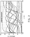
- a set of about 14 chromatic and 3 achromatic solid reflectance standards of different lightness level is sufficient to define meaningful instrument profiles (see Fig. 2 ).
- the solid reflectance standards utilised for instrument profiling have to be long-term stable and in the ideal case temperature-independent. Since in particular brilliant solid reflectance standards with steep slopes in their reflectance spectra are subject to a marked colour change with temperature, ambient temperature conditions during the measurement process have to be stabilised to better than ⁇ 2°C. Temperature corrections can only be performed if temperature coefficients of all solid reflectance standards are known. Furthermore, the surface of each solid reflectance standard should be texture-free (i.e., highly glossy) and easy to clean.
- step B of the method of the present invention geometry instrument profiles for the colour measurement instruments of the network are generated in order to correct differences in geometric measurement conditions.
- Step B of the method of the present invention comprises sub-steps B1, B2 and B3.
- a set of gonioapparent reflectance standards can be measured at at least two measurement geometry configurations and at each of the colour measurement instruments distributed in the network to obtain gonioapparent standard reflectance spectra. Since parameters of the geometry profiling model are wavelength- and angle-independent, the number of gonioapparent reflectance standards, for example, coated panels, needed to define the profile can be kept very low. In one example, in a range of from 3 to 5 of coated panels can be used as gonioapparent reflectance standards. In another example, a set of 3 to 5 coated panels having metallic colour shades of moderate to high lightness travel with viewing angle can be used as gonioapparent reflectance standards and can be sufficient to derive statistically significant model parameters.
- the accuracy of a profile can critically depend on the accuracy of the derivative dR( ⁇ , ⁇ )/d ⁇ in particular at the 15° angle, which has to be estimated numerically.
- dR( ⁇ , ⁇ )/d ⁇ in particular at the 15° angle, which has to be estimated numerically.
- a sufficiently accurate model function has to be fitted to the experimental data to estimate the angle derivative. This already applies to colour measurement instruments equipped with 5 or less viewing angles, where an accurate estimation of the angle derivative is a numerical challenge.
- the gonioapparent reflectance standards can be coated panels or any other appropriate coated or coloured surface as, e. g., ceramic tiles, plastic chips, etc., with isotropic reflectance properties, where the pigment formulation of the coated or coloured surface besides solid pigments contains a sufficient amount of special effect pigments, or any other colour shade anisotropically reflecting collimated incident light.
- the gonioapparent reflectance standard spectra of the set of selected gonioapparent reflectance standards can be measured on each of the colour measurement instruments distributed in the network, for example, on each colour measurement instrument to be consolidated in the network; and at at least two measurement geometry configurations, for example, at at least two combinations of illumination and viewing directions.
- the measurement can be done by using a goniospectrophotometer.
- the gonioapparent reflectance standard spectra and the spectral differences between the master instrument and each colour measurement instrument of the network can be registered at different wavelengths, for example, within the wavelength range 400 nm to 700 nm with a wavelength pitch of 10 nm for each measurement geometry, for each of the solid reflectance standards.
- the gonioapparent reflectance standard spectra and data on spectral differences can be stored in a database.
- step B2 the standard instrument profile for each colour measurement instrument distributed in the network and generated in step A) is applied to the gonioapparent reflectance standard spectra obtained in step B1), i.e. the gonioapparent reflectance standard spectra are corrected by applying the standard instrument profile to the gonioapparent reflectance standard spectra (by using the corresponding error parameters)
- step B3 a geometry instrument profile for each of the colour measurement instruments distributed in the network is generated based on the gonioapparent standard reflectance spectra applied with said standard instrument profile in step B2) that are corrected for photometric and wavelength scale errors.
- the geometry instrument profile can be applied for a pair of measurement instruments.
- a reference measurement instrument (the master instrument) and a secondary colour measurement instrument can be applied to.
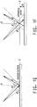
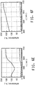
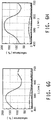
- Fig. 1 depicts representative schematic views of the measurement geometry.
- ⁇ i denotes the illumination angle
- ⁇ e the viewing angle
- ⁇ the corresponding aspecular angle of observation.
- FIG. 1B For tilted measurement geometries ( FIG. 1B ) and rotating of the measurement block about the y-axis ( FIG.
- the illumination and viewing optics are integrated into a compact optics block.
- changes in illumination and viewing angles are always rigidly coupled with each other, since both depend on the orientation of the optics block within each instrument.
- the illumination angle and the corresponding aperture might change slightly, if the light source has to be replaced.
- Fig 1 (FIG. -1B, 1D, and 1F); (i) rotating the measurement block about the x-axis perpendicular to the measurement plane spanned by the illumination and viewing directions ( FIG. 1B ), ii) rotating the optics block about the y-axis oriented parallel to the measurement plane ( FIG 1D ) and (iii) displacement of the measurement or reference plane in the z-direction ( FIG. 1F ).
- sources of systematic errors can be superimposed in practical applications and have to be thoroughly analysed.
- the ratio can be approximated by A*/A ⁇ 1 + 2Az/z o . If the illumination and the viewing areas would stay co-centred at the same position and only the lateral extension is changed, when displacing the measurement plane, there would be an impact on the measurement results only in those cases, where the dimensional scale of sample inhomogeneity is of the same order of magnitude as the change in lateral extension. In practical application, however, both illumination and viewing areas may not stay co-centred when the measurement plane is displaced. If ⁇ z > 0, the illumination area in Fig.
- the most critical angle combination is the one, where illumination and viewing areas move in opposite directions.
- the relative shift of illumination and viewing areas for the 45°/15° measurement geometry is ⁇ y ⁇ 1.5774AZ.
- the smallest relative shift of ⁇ y ⁇ 0.4282 ⁇ z is observed.
- the relative shift of the illumination and viewing areas can have a negative impact on the measurement accuracy if the ratio of their areas has been chosen inappropriately. Specimen-dependent edge losses might occur, if the size of the viewing area is not small enough compared to the illumination area.
- changes of the measurement geometry can be expressed by the first derivative of the reflectance function with respect to the aspecular angle ⁇ . Since generally ⁇ R/ ⁇ ⁇ 0, for ⁇ ⁇ 0 reflectance values are reduced, while for ⁇ > 0 they are enlarged by the same amount, i.e., both changes have to be symmetric with respect to the reference plane.
- This error contribution is proportional to the second derivative of reflectance with respect to viewing angle.
- both geometry-dependent contributions can be combined in a linear mathematical construct with two parameters to be estimated by fitting the model to the experimental data.
- the analytical error model may be replaced by a self-learning neural network system of appropriate topology, which is model-independent and forms its own internal structure to model differences of instrument scales.
- the method of the present invention further comprises step C, including sub-steps C1, C2 and C3.
- step C both the standard instrument profile and the geometry instrument profile are applied to target gonioapparent measurement data
- step C comprises the sub-steps C1, C2 and C3.
- Target gonioapparent measurement data of a target are obtained and can be measured using one or more of the colour measurement instruments distributed in the network.
- step C2 the standard instrument profile generated in step A) is applied to the target gonioapparent measurement data to generate photometric and wavelength scale corrected target measurement data.
- step C3) the geometry instrument profile generated in step B) is applied to the results obtained in step C2, i.e. to the photometric and wavelength scale corrected target measurement data obtained in step C2, to generate the calibrated colour data of the target.
- Another important step in the process chain is the assessment of the performance of the obtained final instrument profiles (standard instrument profile and geometry instrument profile).
- a performance assessment may include analyses of spectral differences between unprofiled and profiled data sets, which also can be converted to specific, e.g. lightness, chroma and hue differences, and total colour differences generated in a uniform colour space.
- the method of the present invention can be used in general to build up a network of managed colour measurement instruments, such as goniospectrophotometers, of high flexibility.
- the method can improve comparability of measurement results obtained at different colour measurement instruments distributed in the network.
- Various configurations can be established.
- a single colour measurement instrument is the master instrument (10) of the network, and one or more secondary colour measurement instruments (21 through 26) can be profiled to have individual profile (11 through 16) to reference the master instrument.
- Secondary colour measurement instruments can be, for example colour measurement instruments at different production sites, different measurement locations, different automotive body shops, or a combination thereof.
- each of the colour measurement instruments distributed in the network is referenced to a master instrument.
- each of the colour measurement instruments distributed in the network is referenced to a digital standard.
- a master instrument can be optional in this configuration, i.e., all colour measurement instruments distributed in the network can be referenced to the same digital standard,
- a digital standard can be a digital data file that can comprise pre-defined spectra data at pre-defined measurement conditions described herein.
- each secondary colour measurement instrument in the network can be profiled to another secondary colour measurement instrument of the network using the same sets of solid reflectance standards and of the gonioapparent reflectance standards, measured under well-controlled conditions on the respective instrument pair.
- the method of the present invention can be used in practical applications where differences in geometrical measurement conditions may occur.
- the method can be used where colour measurement instruments can be slightly tilted by the operator during the measurement process,
- the method can be used where colour measurement instruments can be mounted in a measurement robot used in an application where contact-free measurements have to be carried out, e.g in OEM coating applications.
- the colour measurement instrument network used herein consists of two portable MA-90BR goniospectrophotometers of X-Rite equipped with the three collimated measurement geometries 45°/15°, 45°/45°, 45°/110°, where the sample can be illuminated at the first angle of 45° and viewed at the following three aspecular difference angles [15°, 45°, 110°).
- the instruments provide spectral data within the wavelength range 400nm ⁇ ⁇ ⁇ 700nm with a wavelength pitch of 10 nm for each measurement geometry.
- FIG. 3 displays four error parameters e 1 - e 4 of the utilised composite error model representing the standard instrument profile. Since the profile was determined based on two instruments identical in construction, the error contributions of the wavelength scale ( e 3 ,e 4 ) within the measurement precision were negligible. The error contributions associated with the photometric scale ( e 1 ,e 2 ) were significantly different from zero and dominated the error model.
- the parameter e 1 is a measure of the photometric zero error
- e 2 describes the photometric scale error of the white standard used to calibrate the respective instrument. At each of the measurement geometries (configurations), the contributions of both errors e 1 and e 2 were of comparable order of magnitude. As already noted above, for each configuration, an individual data set exists and was collected.
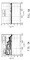
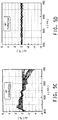
- the spectral differences between the two colour measurement instruments for the measured training or calibration colours at selected measurement geometries before and after profiling are shown in FIG. 5 .
- the uncalibrated (herein referred to as "un-profiled”) spectral residues were distributed asymmetrically relative to the zero line and exhibit marked variations significantly exceeding the statistical measurement error with deviations of up to 2.5%.
- the spectral residues of the calibrated (herein referred to as “profiled”) data set were symmetrically distributed relative to the zero line and statistically distributed with a variance corresponding to the specification of the instrument manufacturer in the technical data sheet.
- the spectral differences at the other two measurement geometries 45°/16° and 45°/110° closely resembled those obtained for the 45°/45° measurement geometry.
- the set of solid reflectance standards utilised for the generation of the standard instrument profiles were chosen so that spectra differences were not statistically significant.
- gonioapparent reflectance standards also known as gonioapparent colour shades
- gonioappearant standard reflectance spectra displayed in FIG. 6 .
- the standard instrument profile generated above was applied to the measured reflectance spectra data to obtain profiled gonioapparent standard reflectance spectra.
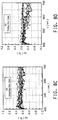
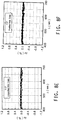
- the profiled gonioapparent standard reflectance spectra obtained were still not centred about zero, particularly at the near specular angle of 15° ( FIG. 8A , 8C , and 8E ). This asymmetry was an indication of slightly different geometrical configurations for both instruments, which have to be reduced by means of a geometry instrument profile.
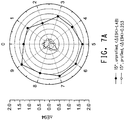
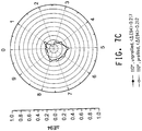
- a geometry instrument profile was derived from the gonioappearant standard reflectance spectra data, as shown in FIG. 6 , leading to the performance data displayed in FIGs. 7 (colour difference data) and 8 (spectral differences).
- the standard instrument profile generated above was applied to the measured reflectance spectra data from the 10 gonioapparent reflectance standards now treated as target gonioapparent measurement data to generate photometric and wavelength scale corrected target measurement data.
- the geometry instrument profile generated above was applied to the photometric and wavelength scale corrected target measurement data.
- FIG. 7 the residual colour differences at the near-specular angle of 15° were reduced significantly after applying the geometry instrument profile ( FIG. 7A ), while the residual colour differences at the other two viewing angles (45°, 110°) were not reduced significantly ( FIG. 7B and 7C ).
- Calibrated colour data are shown in Fig. 8 ( FIG. 8B , 8D , and 8F ).
Landscapes
- Physics & Mathematics (AREA)
- Spectroscopy & Molecular Physics (AREA)
- General Physics & Mathematics (AREA)
- Spectrometry And Color Measurement (AREA)
- Manipulator (AREA)
Claims (7)
- Ein Verfahren zum Generieren von kalibrierten Farbdaten eines Zieles unter Verwendung von Farbmessinstrumenten, welche in dem Netzwerk verteilt sind, wobei das Verfahren die Schritte aufweist:A) Generieren zumindest eines Standard-Instrumentenprofiles für die Farbmessinstrumente, welche in dem Netzwerk verteilt sind, um photometrische und Wellenlängen Skalierungsunterschiede zu korrigieren, wobei ein Standard-Instrumentenprofil ein Instrumentenprofil eines Farb-Messinstrumentes ist, in Bezug auf die Korrektur von photometrischen und Wellenlängen Skalierungsunterschieden zu einem Primär- oder Referenzinstrument oder einem digitalen Standard , wobei der Schritt A) aufweist:A1) Messen eines Sets von Feststtoff Reflexionsgrad Standards bei zumindest zwei Mess-Geometriekonfigurationen und bei jedem der Farbmessinstrumente, welche in dem Netzwerk verteilt sind, um Feststoff Standard Reflexionsgradspektren der Feststoff Reflexionsgradstandards zu erhalten, undA2) Generieren von zumindest einem Standard-Instrumentenprofil für jedes der Farbmessinstrumente, welche in dem Netzwerk verteilt sind, basierend auf den Feststoff Standard Reflexionsgradspektren, um photometrische und Wellenlängen Skalierungsunterschiede zu korrigieren; undB) Generieren von zumindest einem Geometrie Instrumentenprofil für die Farbmessinstrumente, welche in dem Netzwerk verteilt sind, um Geometrie Skalierungsunterschiede zu korrigieren, welche von einer gekippten und/oder verstellten Mess-Geometrie verursacht werden, wobei ein Geometrie Instrumentenprofil ein Geometrieprofil eines Farbmessinstruments ist, in Bezug auf die Korrektur von Winkel Skalierungsunterschieden zu einem Primär- oder Referenzinstrument oder einem digitalen Standard, wobei Schritt B) aufweist:B1) Messen eines Sets von gonioapparenten Reflexionsgrad Standards bei zumindest zwei Mess-Geometriekonfigurationen, welche zumindest zwei Kombinationen von Beleuchtungs- und Betrachtungsrichtungen aufweisen und bei jedem der Farbmessinstrumente, welche in dem Netzwerk verteilt sind, um Reflexionsgradspektren des genioapparenten Standards zu erhalten,B2) Anwenden des im Schritt A) generierten zumindest einem Standard Instrumentenprofiles auf die Reflexionsgradspektren des gonioapparenten Standards, welche im Schritt B1) erhalten wurden, um profilierte Reflexionsgradspektren des gonioapparenten Standards zu erhalten, undB3) Generieren von zumindest einem Geometrie Instrumentenprofil für jedes der Farbmessinstrumente, welche in dem Netzwerk verteilt sind, um Geometrie Skalierungsunterschiede zu korrigieren, basierend auf den profilierten Reflexionsgradspektren des gonioapparenten Standards ; undC) Generieren der kalibrierten Farbdaten des Zieles, wobei der Schritt C) aufweist:C1) Erhalten von gonioapparenten Ziel-Messdaten des Zieles unter Verwendung eines oder mehrerer der Farbmessinstrumente, welche in dem Netzwerk verteilt sind;C2) Anwenden des zumindest einen Standard Instrumentenprofiles, welches in Schritt A) generiert wurde, auf die gonioapparenten Ziel-Messdaten, um photometrische und Wellenlängen Skalierungs-korrigierte Ziel-Messdaten zu erhalten, undC3) Anwenden des zumindest einen Geometrie Instrumentenprofiles, welches in Schritt B) generiert wurde, auf die photometrischen und Wellenlängen Skalierungs-korrigierten Ziel-Messdaten, welche in Schritt C2) erhalten wurden, um die kalibrierten Farbdaten des Zieles zu generieren.
- Das Verfahren nach Anspruch 1, wobei die Farbmessinstrumente ein Goniospectrophotometer aufweisen.
- Das Verfahren nach Anspruch1 oder 2, wobei jedes der Farbmessinstrumente, welche in dem Netzwerk verteilt sind, auf ein Master-Instrument bezogen ist.
- Das Verfahren nach einem der Ansprüche 1 bis 3, wobei jeder der Farbmessinstrumente, welche in dem Netzwerk verteilt sind, auf einen digitalen Standard bezogen ist
- Verwendung des Verfahrens nach einem der Ansprüche 1 bis 4 in der Farbherstellung
- Verwendung des Verfahrens nach einem der Ansprüche 1 bis 4 in der Farbentwicklung.
- Verwendung des Verfahrens nach einem der Ansprüche 1 bis 4 in der Fahrzeug OEM Beschichtung.
Applications Claiming Priority (2)
| Application Number | Priority Date | Filing Date | Title |
|---|---|---|---|
| US28556909P | 2009-12-11 | 2009-12-11 | |
| PCT/US2010/058167 WO2011071708A1 (en) | 2009-12-11 | 2010-11-29 | Method for generating calibrated colour data |
Publications (2)
| Publication Number | Publication Date |
|---|---|
| EP2510322A1 EP2510322A1 (de) | 2012-10-17 |
| EP2510322B1 true EP2510322B1 (de) | 2018-08-15 |
Family
ID=43569898
Family Applications (1)
| Application Number | Title | Priority Date | Filing Date |
|---|---|---|---|
| EP10793082.8A Not-in-force EP2510322B1 (de) | 2009-12-11 | 2010-11-29 | Verfahren zur erzeugung von kalibrierten farbdaten |
Country Status (6)
| Country | Link |
|---|---|
| US (1) | US10107685B2 (de) |
| EP (1) | EP2510322B1 (de) |
| CN (1) | CN102652254B (de) |
| CA (1) | CA2781121A1 (de) |
| MX (1) | MX2012006489A (de) |
| WO (1) | WO2011071708A1 (de) |
Families Citing this family (8)
| Publication number | Priority date | Publication date | Assignee | Title |
|---|---|---|---|---|
| ES2467590B2 (es) * | 2012-11-12 | 2015-07-21 | Universidad De Alicante | Procedimiento para estimar el color de materiales gonioaparentes |
| US9782516B2 (en) | 2013-03-15 | 2017-10-10 | Abbott Cardiovascular Systems Inc. | Tissue adhesive coatings for drug coated balloon |
| EP3239669B1 (de) * | 2014-12-16 | 2025-11-26 | Konica Minolta, Inc. | Vorrichtung zur verarbeitung kolorimetrischer daten, system zur verarbeitung kolorimetrischer daten, verfahren zur verarbeitung kolorimetrischer daten und programm zur verarbeitung kolorimetrischer daten |
| EP3078950B8 (de) * | 2015-04-08 | 2024-06-26 | X-Rite Europe GmbH | Farbmessverfahren und farbmessgerät |
| CN106052877B (zh) * | 2016-05-25 | 2018-01-19 | 敦煌研究院 | 壁画绘画材料多光谱图像色彩标准色卡及其制作方法 |
| CN111936832A (zh) | 2018-03-26 | 2020-11-13 | 惠普发展公司,有限责任合伙企业 | 对光谱测量设备进行仿真 |
| JP7367562B2 (ja) * | 2020-03-02 | 2023-10-24 | マツダ株式会社 | 艶評価装置および該方法 |
| JP7310750B2 (ja) * | 2020-08-07 | 2023-07-19 | トヨタ自動車株式会社 | 色味補正システム及び色味補正方法 |
Family Cites Families (4)
| Publication number | Priority date | Publication date | Assignee | Title |
|---|---|---|---|---|
| US6870614B2 (en) * | 2002-05-30 | 2005-03-22 | General Electric Company | Method, system and computer product for formulating a bi-directional color match |
| WO2005106409A1 (en) | 2004-04-30 | 2005-11-10 | X-Rite, Incorporated | Color measurement engine with uv filtered illumination |
| CN201000365Y (zh) | 2007-05-24 | 2008-01-02 | 赖知军 | 便携式测色仪 |
| DE102008010562B4 (de) * | 2008-02-22 | 2015-11-12 | Audi Ag | Verfahren zum Instrumenten-Abgleich von Mehrwinkel-Farbmessgeräten |
-
2010
- 2010-11-29 WO PCT/US2010/058167 patent/WO2011071708A1/en not_active Ceased
- 2010-11-29 US US12/954,996 patent/US10107685B2/en active Active
- 2010-11-29 MX MX2012006489A patent/MX2012006489A/es not_active Application Discontinuation
- 2010-11-29 EP EP10793082.8A patent/EP2510322B1/de not_active Not-in-force
- 2010-11-29 CN CN201080055744.3A patent/CN102652254B/zh not_active Expired - Fee Related
- 2010-11-29 CA CA2781121A patent/CA2781121A1/en not_active Abandoned
Non-Patent Citations (1)
| Title |
|---|
| None * |
Also Published As
| Publication number | Publication date |
|---|---|
| WO2011071708A1 (en) | 2011-06-16 |
| CN102652254B (zh) | 2014-12-24 |
| CN102652254A (zh) | 2012-08-29 |
| US10107685B2 (en) | 2018-10-23 |
| CA2781121A1 (en) | 2011-06-16 |
| EP2510322A1 (de) | 2012-10-17 |
| US20110143017A1 (en) | 2011-06-16 |
| MX2012006489A (es) | 2012-07-03 |
Similar Documents
| Publication | Publication Date | Title |
|---|---|---|
| US10107685B2 (en) | Method for generating and applying instrument profiles | |
| AU2004248204B2 (en) | Recipe calculation method for matt colour shades | |
| US9417187B2 (en) | Method for determining the surface gloss of a colour standard | |
| Leloup et al. | Design of an instrument for measuring the spectral bidirectional scatter distribution function | |
| KR100264163B1 (ko) | 분광측정장치 및 그 표준화 방법 | |
| EP2000794B1 (de) | Vorrichtung und Verfahren zum Bestimmen einer spektral aufgelösten bi-direktionalen Erscheinungseigenschaft einer Oberfläche | |
| US9874476B2 (en) | Colour recipe calculating method for matt colour standards | |
| Nordgren et al. | Comparison of stellar angular diameters from the NPOI, the Mark III optical interferometer, and the Infrared Flux Method | |
| EP2331921B1 (de) | Verfahren zur farbabstimmung | |
| Johnson et al. | A method of realizing spectral irradiance based on an absolute cryogenic radiometer | |
| Feng et al. | Color prediction of metallic coatings from measurements at common geometries in portable multiangle spectrophotometers | |
| Chunnilall et al. | Infrared hemispherical reflectance measurements in the 2.5 µm to 50 µm wavelength region using a Fourier transform spectrometer | |
| JPH0580614B2 (de) | ||
| US3545871A (en) | Differential-port sphere for absolute diffuse spectral reflectance measurements and method | |
| Nadal et al. | 0: 45 Surface Color | |
| Zarobila et al. | Measuring gloss using spectral reflectance | |
| Nadal et al. | NIST 0: 45 reflectometer | |
| CN115046940A (zh) | 一种基于角度特性校准的高光谱物体反射率测量方法 | |
| Charrière et al. | Comparison of specular gloss values from a spectrally resolved five-axis goniometer and a reference goniophotometer | |
| Rich | Instruments and Methods for the Colour Measurements Required in Colour Engineering | |
| Brooks | Quantifying Appearance for Opaque Surfaces Using Spectral Bidirectional Reflectivity | |
| Rich | Colorimetry, Color Specifications, and Production Tolerances by Visual and Instrumental Means | |
| Stewart | Solar Measurements | |
| Kamiński et al. | Accuracy of determining spectral reflectance coefficients in a function of time | |
| Rich | Colorimetry, Color Specifications, and Production Tolerances by |
Legal Events
| Date | Code | Title | Description |
|---|---|---|---|
| PUAI | Public reference made under article 153(3) epc to a published international application that has entered the european phase |
Free format text: ORIGINAL CODE: 0009012 |
|
| 17P | Request for examination filed |
Effective date: 20120523 |
|
| AK | Designated contracting states |
Kind code of ref document: A1 Designated state(s): AL AT BE BG CH CY CZ DE DK EE ES FI FR GB GR HR HU IE IS IT LI LT LU LV MC MK MT NL NO PL PT RO RS SE SI SK SM TR |
|
| DAX | Request for extension of the european patent (deleted) | ||
| RAP1 | Party data changed (applicant data changed or rights of an application transferred) |
Owner name: COATINGS FOREIGN IP CO. LLC |
|
| 17Q | First examination report despatched |
Effective date: 20151023 |
|
| GRAP | Despatch of communication of intention to grant a patent |
Free format text: ORIGINAL CODE: EPIDOSNIGR1 |
|
| STAA | Information on the status of an ep patent application or granted ep patent |
Free format text: STATUS: GRANT OF PATENT IS INTENDED |
|
| INTG | Intention to grant announced |
Effective date: 20180222 |
|
| GRAS | Grant fee paid |
Free format text: ORIGINAL CODE: EPIDOSNIGR3 |
|
| GRAA | (expected) grant |
Free format text: ORIGINAL CODE: 0009210 |
|
| STAA | Information on the status of an ep patent application or granted ep patent |
Free format text: STATUS: THE PATENT HAS BEEN GRANTED |
|
| AK | Designated contracting states |
Kind code of ref document: B1 Designated state(s): AL AT BE BG CH CY CZ DE DK EE ES FI FR GB GR HR HU IE IS IT LI LT LU LV MC MK MT NL NO PL PT RO RS SE SI SK SM TR |
|
| REG | Reference to a national code |
Ref country code: CH Ref legal event code: EP Ref country code: GB Ref legal event code: FG4D Ref country code: AT Ref legal event code: REF Ref document number: 1030327 Country of ref document: AT Kind code of ref document: T Effective date: 20180815 |
|
| REG | Reference to a national code |
Ref country code: IE Ref legal event code: FG4D |
|
| REG | Reference to a national code |
Ref country code: DE Ref legal event code: R096 Ref document number: 602010052804 Country of ref document: DE |
|
| REG | Reference to a national code |
Ref country code: NL Ref legal event code: MP Effective date: 20180815 |
|
| REG | Reference to a national code |
Ref country code: LT Ref legal event code: MG4D |
|
| REG | Reference to a national code |
Ref country code: AT Ref legal event code: MK05 Ref document number: 1030327 Country of ref document: AT Kind code of ref document: T Effective date: 20180815 |
|
| PG25 | Lapsed in a contracting state [announced via postgrant information from national office to epo] |
Ref country code: FI Free format text: LAPSE BECAUSE OF FAILURE TO SUBMIT A TRANSLATION OF THE DESCRIPTION OR TO PAY THE FEE WITHIN THE PRESCRIBED TIME-LIMIT Effective date: 20180815 Ref country code: NL Free format text: LAPSE BECAUSE OF FAILURE TO SUBMIT A TRANSLATION OF THE DESCRIPTION OR TO PAY THE FEE WITHIN THE PRESCRIBED TIME-LIMIT Effective date: 20180815 Ref country code: LT Free format text: LAPSE BECAUSE OF FAILURE TO SUBMIT A TRANSLATION OF THE DESCRIPTION OR TO PAY THE FEE WITHIN THE PRESCRIBED TIME-LIMIT Effective date: 20180815 Ref country code: NO Free format text: LAPSE BECAUSE OF FAILURE TO SUBMIT A TRANSLATION OF THE DESCRIPTION OR TO PAY THE FEE WITHIN THE PRESCRIBED TIME-LIMIT Effective date: 20181115 Ref country code: BG Free format text: LAPSE BECAUSE OF FAILURE TO SUBMIT A TRANSLATION OF THE DESCRIPTION OR TO PAY THE FEE WITHIN THE PRESCRIBED TIME-LIMIT Effective date: 20181115 Ref country code: SE Free format text: LAPSE BECAUSE OF FAILURE TO SUBMIT A TRANSLATION OF THE DESCRIPTION OR TO PAY THE FEE WITHIN THE PRESCRIBED TIME-LIMIT Effective date: 20180815 Ref country code: AT Free format text: LAPSE BECAUSE OF FAILURE TO SUBMIT A TRANSLATION OF THE DESCRIPTION OR TO PAY THE FEE WITHIN THE PRESCRIBED TIME-LIMIT Effective date: 20180815 Ref country code: IS Free format text: LAPSE BECAUSE OF FAILURE TO SUBMIT A TRANSLATION OF THE DESCRIPTION OR TO PAY THE FEE WITHIN THE PRESCRIBED TIME-LIMIT Effective date: 20181215 Ref country code: RS Free format text: LAPSE BECAUSE OF FAILURE TO SUBMIT A TRANSLATION OF THE DESCRIPTION OR TO PAY THE FEE WITHIN THE PRESCRIBED TIME-LIMIT Effective date: 20180815 Ref country code: GR Free format text: LAPSE BECAUSE OF FAILURE TO SUBMIT A TRANSLATION OF THE DESCRIPTION OR TO PAY THE FEE WITHIN THE PRESCRIBED TIME-LIMIT Effective date: 20181116 |
|
| PG25 | Lapsed in a contracting state [announced via postgrant information from national office to epo] |
Ref country code: AL Free format text: LAPSE BECAUSE OF FAILURE TO SUBMIT A TRANSLATION OF THE DESCRIPTION OR TO PAY THE FEE WITHIN THE PRESCRIBED TIME-LIMIT Effective date: 20180815 Ref country code: HR Free format text: LAPSE BECAUSE OF FAILURE TO SUBMIT A TRANSLATION OF THE DESCRIPTION OR TO PAY THE FEE WITHIN THE PRESCRIBED TIME-LIMIT Effective date: 20180815 Ref country code: LV Free format text: LAPSE BECAUSE OF FAILURE TO SUBMIT A TRANSLATION OF THE DESCRIPTION OR TO PAY THE FEE WITHIN THE PRESCRIBED TIME-LIMIT Effective date: 20180815 |
|
| PG25 | Lapsed in a contracting state [announced via postgrant information from national office to epo] |
Ref country code: IT Free format text: LAPSE BECAUSE OF FAILURE TO SUBMIT A TRANSLATION OF THE DESCRIPTION OR TO PAY THE FEE WITHIN THE PRESCRIBED TIME-LIMIT Effective date: 20180815 Ref country code: EE Free format text: LAPSE BECAUSE OF FAILURE TO SUBMIT A TRANSLATION OF THE DESCRIPTION OR TO PAY THE FEE WITHIN THE PRESCRIBED TIME-LIMIT Effective date: 20180815 Ref country code: RO Free format text: LAPSE BECAUSE OF FAILURE TO SUBMIT A TRANSLATION OF THE DESCRIPTION OR TO PAY THE FEE WITHIN THE PRESCRIBED TIME-LIMIT Effective date: 20180815 Ref country code: CZ Free format text: LAPSE BECAUSE OF FAILURE TO SUBMIT A TRANSLATION OF THE DESCRIPTION OR TO PAY THE FEE WITHIN THE PRESCRIBED TIME-LIMIT Effective date: 20180815 Ref country code: ES Free format text: LAPSE BECAUSE OF FAILURE TO SUBMIT A TRANSLATION OF THE DESCRIPTION OR TO PAY THE FEE WITHIN THE PRESCRIBED TIME-LIMIT Effective date: 20180815 Ref country code: PL Free format text: LAPSE BECAUSE OF FAILURE TO SUBMIT A TRANSLATION OF THE DESCRIPTION OR TO PAY THE FEE WITHIN THE PRESCRIBED TIME-LIMIT Effective date: 20180815 |
|
| REG | Reference to a national code |
Ref country code: DE Ref legal event code: R097 Ref document number: 602010052804 Country of ref document: DE |
|
| PG25 | Lapsed in a contracting state [announced via postgrant information from national office to epo] |
Ref country code: SK Free format text: LAPSE BECAUSE OF FAILURE TO SUBMIT A TRANSLATION OF THE DESCRIPTION OR TO PAY THE FEE WITHIN THE PRESCRIBED TIME-LIMIT Effective date: 20180815 Ref country code: SM Free format text: LAPSE BECAUSE OF FAILURE TO SUBMIT A TRANSLATION OF THE DESCRIPTION OR TO PAY THE FEE WITHIN THE PRESCRIBED TIME-LIMIT Effective date: 20180815 Ref country code: DK Free format text: LAPSE BECAUSE OF FAILURE TO SUBMIT A TRANSLATION OF THE DESCRIPTION OR TO PAY THE FEE WITHIN THE PRESCRIBED TIME-LIMIT Effective date: 20180815 |
|
| PLBE | No opposition filed within time limit |
Free format text: ORIGINAL CODE: 0009261 |
|
| STAA | Information on the status of an ep patent application or granted ep patent |
Free format text: STATUS: NO OPPOSITION FILED WITHIN TIME LIMIT |
|
| REG | Reference to a national code |
Ref country code: CH Ref legal event code: PL |
|
| 26N | No opposition filed |
Effective date: 20190516 |
|
| GBPC | Gb: european patent ceased through non-payment of renewal fee |
Effective date: 20181129 |
|
| PG25 | Lapsed in a contracting state [announced via postgrant information from national office to epo] |
Ref country code: MC Free format text: LAPSE BECAUSE OF FAILURE TO SUBMIT A TRANSLATION OF THE DESCRIPTION OR TO PAY THE FEE WITHIN THE PRESCRIBED TIME-LIMIT Effective date: 20180815 Ref country code: LU Free format text: LAPSE BECAUSE OF NON-PAYMENT OF DUE FEES Effective date: 20181129 |
|
| REG | Reference to a national code |
Ref country code: BE Ref legal event code: MM Effective date: 20181130 |
|
| REG | Reference to a national code |
Ref country code: IE Ref legal event code: MM4A |
|
| PG25 | Lapsed in a contracting state [announced via postgrant information from national office to epo] |
Ref country code: LI Free format text: LAPSE BECAUSE OF NON-PAYMENT OF DUE FEES Effective date: 20181130 Ref country code: CH Free format text: LAPSE BECAUSE OF NON-PAYMENT OF DUE FEES Effective date: 20181130 Ref country code: SI Free format text: LAPSE BECAUSE OF FAILURE TO SUBMIT A TRANSLATION OF THE DESCRIPTION OR TO PAY THE FEE WITHIN THE PRESCRIBED TIME-LIMIT Effective date: 20180815 |
|
| PG25 | Lapsed in a contracting state [announced via postgrant information from national office to epo] |
Ref country code: IE Free format text: LAPSE BECAUSE OF NON-PAYMENT OF DUE FEES Effective date: 20181129 Ref country code: FR Free format text: LAPSE BECAUSE OF NON-PAYMENT OF DUE FEES Effective date: 20181130 |
|
| PG25 | Lapsed in a contracting state [announced via postgrant information from national office to epo] |
Ref country code: BE Free format text: LAPSE BECAUSE OF NON-PAYMENT OF DUE FEES Effective date: 20181130 |
|
| PG25 | Lapsed in a contracting state [announced via postgrant information from national office to epo] |
Ref country code: GB Free format text: LAPSE BECAUSE OF NON-PAYMENT OF DUE FEES Effective date: 20181129 |
|
| PG25 | Lapsed in a contracting state [announced via postgrant information from national office to epo] |
Ref country code: MT Free format text: LAPSE BECAUSE OF NON-PAYMENT OF DUE FEES Effective date: 20181129 |
|
| PG25 | Lapsed in a contracting state [announced via postgrant information from national office to epo] |
Ref country code: TR Free format text: LAPSE BECAUSE OF FAILURE TO SUBMIT A TRANSLATION OF THE DESCRIPTION OR TO PAY THE FEE WITHIN THE PRESCRIBED TIME-LIMIT Effective date: 20180815 |
|
| PG25 | Lapsed in a contracting state [announced via postgrant information from national office to epo] |
Ref country code: PT Free format text: LAPSE BECAUSE OF FAILURE TO SUBMIT A TRANSLATION OF THE DESCRIPTION OR TO PAY THE FEE WITHIN THE PRESCRIBED TIME-LIMIT Effective date: 20180815 |
|
| PG25 | Lapsed in a contracting state [announced via postgrant information from national office to epo] |
Ref country code: MK Free format text: LAPSE BECAUSE OF NON-PAYMENT OF DUE FEES Effective date: 20180815 Ref country code: HU Free format text: LAPSE BECAUSE OF FAILURE TO SUBMIT A TRANSLATION OF THE DESCRIPTION OR TO PAY THE FEE WITHIN THE PRESCRIBED TIME-LIMIT; INVALID AB INITIO Effective date: 20101129 Ref country code: CY Free format text: LAPSE BECAUSE OF FAILURE TO SUBMIT A TRANSLATION OF THE DESCRIPTION OR TO PAY THE FEE WITHIN THE PRESCRIBED TIME-LIMIT Effective date: 20180815 |
|
| REG | Reference to a national code |
Ref country code: DE Ref legal event code: R081 Ref document number: 602010052804 Country of ref document: DE Owner name: AXALTA COATING SYSTEMS GMBH, CH Free format text: FORMER OWNER: COATINGS FOREIGN IP CO. LLC, WILMINGTON, DEL., US |
|
| P01 | Opt-out of the competence of the unified patent court (upc) registered |
Effective date: 20230510 |
|
| PGFP | Annual fee paid to national office [announced via postgrant information from national office to epo] |
Ref country code: DE Payment date: 20231129 Year of fee payment: 14 |
|
| REG | Reference to a national code |
Ref country code: DE Ref legal event code: R119 Ref document number: 602010052804 Country of ref document: DE |
|
| PG25 | Lapsed in a contracting state [announced via postgrant information from national office to epo] |
Ref country code: DE Free format text: LAPSE BECAUSE OF NON-PAYMENT OF DUE FEES Effective date: 20250603 |