EP2510372B1 - Vorrichtung zur detektion von magnetresonanzsignalen - Google Patents
Vorrichtung zur detektion von magnetresonanzsignalen Download PDFInfo
- Publication number
- EP2510372B1 EP2510372B1 EP10834080.3A EP10834080A EP2510372B1 EP 2510372 B1 EP2510372 B1 EP 2510372B1 EP 10834080 A EP10834080 A EP 10834080A EP 2510372 B1 EP2510372 B1 EP 2510372B1
- Authority
- EP
- European Patent Office
- Prior art keywords
- magnetic resonance
- magnetic
- resonance sensor
- shield member
- sensor
- Prior art date
- Legal status (The legal status is an assumption and is not a legal conclusion. Google has not performed a legal analysis and makes no representation as to the accuracy of the status listed.)
- Active
Links
Images


Classifications
-
- G—PHYSICS
- G01—MEASURING; TESTING
- G01R—MEASURING ELECTRIC VARIABLES; MEASURING MAGNETIC VARIABLES
- G01R33/00—Arrangements or instruments for measuring magnetic variables
- G01R33/20—Arrangements or instruments for measuring magnetic variables involving magnetic resonance
- G01R33/28—Details of apparatus provided for in groups G01R33/44 - G01R33/64
- G01R33/32—Excitation or detection systems, e.g. using radio frequency signals
- G01R33/34—Constructional details, e.g. resonators, specially adapted to MR
- G01R33/341—Constructional details, e.g. resonators, specially adapted to MR comprising surface coils
-
- G—PHYSICS
- G01—MEASURING; TESTING
- G01R—MEASURING ELECTRIC VARIABLES; MEASURING MAGNETIC VARIABLES
- G01R33/00—Arrangements or instruments for measuring magnetic variables
- G01R33/20—Arrangements or instruments for measuring magnetic variables involving magnetic resonance
- G01R33/28—Details of apparatus provided for in groups G01R33/44 - G01R33/64
- G01R33/42—Screening
- G01R33/422—Screening of the radio frequency field
-
- G—PHYSICS
- G01—MEASURING; TESTING
- G01R—MEASURING ELECTRIC VARIABLES; MEASURING MAGNETIC VARIABLES
- G01R33/00—Arrangements or instruments for measuring magnetic variables
- G01R33/20—Arrangements or instruments for measuring magnetic variables involving magnetic resonance
- G01R33/28—Details of apparatus provided for in groups G01R33/44 - G01R33/64
- G01R33/32—Excitation or detection systems, e.g. using radio frequency signals
- G01R33/36—Electrical details, e.g. matching or coupling of the coil to the receiver
- G01R33/3628—Tuning/matching of the transmit/receive coil
-
- G—PHYSICS
- G01—MEASURING; TESTING
- G01R—MEASURING ELECTRIC VARIABLES; MEASURING MAGNETIC VARIABLES
- G01R33/00—Arrangements or instruments for measuring magnetic variables
- G01R33/20—Arrangements or instruments for measuring magnetic variables involving magnetic resonance
- G01R33/44—Arrangements or instruments for measuring magnetic variables involving magnetic resonance using nuclear magnetic resonance [NMR]
- G01R33/441—Nuclear Quadrupole Resonance [NQR] Spectroscopy and Imaging
Definitions
- the present invention relates to an apparatus suitable for detecting Magnetic Resonance (MR) signals.
- MR Magnetic Resonance
- MR sensors based on Faraday Law detection may couple to both electric and magnetic field components of Radio Frequency Interference (RFI).
- RFI Radio Frequency Interference
- This RFI is known to emanate from both natural and man-made sources.
- Electric coupling can occur when common mode voltages on the sensor structure are generated through capacitive coupling to ambient electric fields (such as RF electric field voltages and gradients due to being in close proximity to human limbs).
- Magnetic coupling can occur when RFI magnetic fields thread the aperture of the sensor used for detection. These magnetic fields may originate from distant transmitters or close-in sources such as nearby mains wiring.
- electromagnetic shielding such as an electrically conductive box or a shielded room
- electromagnetic shielding is used to prevent extraneous RFI from interfering with the MR signal.
- such techniques are not suitable in many potential applications of MR detection.
- WO 2008/104895 describes apparatus for magnetic resonance excitation and detection at two measurement frequencies using planar coils.
- the coils are shielded by a ground plane.
- US 2009/251145 describes two inductively coupled coils, a first coil for transmitting and receiving a magnetic resonance signal and a second coil for changing a resonance frequency of the first coil.
- the second coil includes a switch that is used to switch between different resonance operating frequencies during magnetic resonance measurements.
- An RF shield may be placed to the second coil on the other side of the first coil.
- US 2005/059882 is intended for use in NMR imaging of human heads.
- a dome-shaped resonator is described with a similarly shaped dome-shaped shield that is in close proximity to the resonator.
- WO 2007 / 109426 describes various embodiments of loop resonators that have shields associated with them.
- the resonators and shields are part of an NMR imaging system.
- the shields have planar portions and angled wings which shield the loop resonators from each other.
- the invention provides an apparatus as claimed in claim 1. Further features of the invention are apparent from the dependent claims 2-15.
- the depth of the concavity of the shield member is at least 30% of the diameter of the magnetic resonance sensor.
- the shield member is composed of a mesh.
- the magnetic resonance sensor is a single turn loop or ribbon.
- the magnetic resonance sensor is a multi-turn loop or ribbon.
- the magnetic resonator is a single turn loop or ribbon.
- the magnetic resonator is a multi turn loop or ribbon.
- the capacitor is connected halfway along the length of the primary winding of the isolation transformer.
- the inverting circuit is a 1:1 impedance ratio transformer with counter-fed windings.
- the magnetic resonance sensor comprises an inductor and at least one capacitor.
- capacitors there are an even number of capacitors arranged symmetrically relative to the inductor.
- the inductor is a single turn inductive loop or ribbon.
- the inductor is a multi-turn inductive coil.
- the voltage distribution electrodes are linked by an electrical connector extending along an edge of the magnetic resonance sensor.
- magnetic resonance refers to both Nuclear Magnetic Resonance (NMR) and Nuclear Quadrupole Resonance (NQR).
- NMR and NQR are methods having wide application in measurement and characterisation of materials. These methods are routinely used as a laboratory tool to investigate bonding and molecular structure. They have also found use in real-time detection and characterisation of minerals and other substances such as narcotics or explosives.
- an apparatus suitable for detecting magnetic resonance signals comprising a magnetic resonance sensor arranged to respond to magnetic resonance signals.
- the apparatus has components for reducing the effects of magnetic coupling and optionally, also electric coupling on the magnetic resonance sensor.
- magnetic coupling refers to the situation where the unwanted output terminal voltage is driven predominantly by interfering magnetic fields.
- electric coupling refers to the additional case where the unwanted terminal voltage is also driven by interfering electric fields. Strictly speaking, for non-zero frequency disturbances the interfering magnetic and electric fields are in any case coupled through Maxwell's equations. However, the terms “electric coupling” and “magnetic coupling” still retain meaning in, for example, a quasi-static approximation to the interference problem.
- Electric coupling may occur, for instance, when common mode voltages on the sensor structure are generated through capacitive coupling to ambient electric fields. These voltages may result in sensor terminal voltages due to asymmetrical impedance distribution on each side of the sensor terminals. Alternatively, electric field gradients can contribute to terminal voltages, even in the case of symmetric impedance distribution at the terminal. The problem of electric coupling is especially severe in close proximity to human limbs, which may support significant RF electric field voltages and gradients.
- Radiofrequency interference magnetic fields thread the aperture of the inductor used for Faraday detection. These magnetic fields may originally emanate from distant transmitters located in the far field. In this case the inductor used for detection behaves as a small loop antenna receiver. Other close-in sources may also contribute to RFI magnetic fields, such as nearby mains wiring.
- RFID radiofrequency interference
- radiofrequency (RF) electromagnetic near-fields from the MR sensor are employed to excite resonances in materials. That is, in the embodiment, as in many applications known in the art, the MR sensor may be used to both excite and detect MR signals.
- the configuration of sensors to provide both excitation of resonances in materials and detection of MR signals is known to persons skilled in the art. However, in the case where excitation of resonances in materials is provided by other apparatus, the embodiment may be used to detect MR signals only.
- the sensor RF near fields may be applied to materials either in the form of discrete pulses or as a continuous wave (CW) excitation.
- the response of the material may be regarded as a time varying magnetisation having an associated RF magnetic field.
- RF field excited due to sample magnetisation by the applied stimulus impinges on the near-field region of a sensor and voltages are developed at output terminals of the sensor. These terminal voltages are proportional to the time rate change of magnetic flux threading the sensor aperture, thus enabling magnetic resonance signals to be detected and processed.
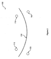
- Figure 1 is a schematic perspective view which illustrates the physical arrangement of the apparatus 100 for detecting magnetic resonance signals of the embodiment.
- the purpose of the physical arrangement shown in Figure 1 is to reduce interference due to magnetic coupling.
- Figure 8 is a schematic plan view of the apparatus in one application where the target sample is material 320 on a conveyor 310, which shows the apparatus 100 facing the target sample as indicated generally by arrow A.
- the apparatus 100 comprises a magnetic resonance sensor 110 adapted to respond to magnetic resonance signal, a shield member 130 electrically isolated from the MR sensor 110 and adapted to shield the magnetic resonance sensor from magnetic coupling, and a magnetic resonator 150 electrically isolated from the shield member 130 and the magnetic resonance sensor 110.
- the elements of the apparatus 100 set up a reference frame which enable attribution of mitigation of the effect of sources of magnetic coupling to particular components of the apparatus. That is, when the magnetic resonance sensor 110 faces the target, the shield member 130 is behind the magnetic resonance sensor to shield the magnetic resonance sensor 110 from magnetic coupling with sources other than magnetic resonance signal from the target. Magnetic coupling which is not, or cannot, be blocked by the shield member 130 is at least partially compensated for by the magnetic resonator 150 as described in further detail below.
- the magnetic resonance sensor 110 is a circular single turn inductive loop having tuning elements and output circuitry 115.
- the tuning elements tune the magnetic resonance sensor 110 to about or close to a desired or predetermined magnetic resonance operating frequency when the displacement between the magnetic resonance sensor 110 and the shield member 130 is fixed in a given configuration.
- the tuning elements 115 also enable the desired excitation to be delivered. Such tuning elements are well understood in the art and accordingly are not described herein.
- the output allows a magnetic resonance signal voltage to be obtained.
- the magnetic resonance sensor 110 need not be a circular single turn loop.
- the shape of the magnetic resonance sensor can be different and/or can be a multi-turn loop or a ribbon etc.
- a number of factors will influence the selection of the type and shape of MR sensor 110, including the desired operating frequency of the MR sensor and/or the application of the MR sensor.
- a multi-turn loop is advantageous as it reduces the physical size of the required tuning capacitance.
- a more elongate shape rather than a circle may be preferred such that the overall dimensions of the device are not unwieldy.
- the shield member 130 is a dished, circular conductive member. It is envisaged however that the shield member need not be circular but in alternative embodiments can be elliptical or rectangular to match or complement the shape of the MR sensor.
- the magnetic resonator 150 is a circular single turn loop having tuning elements 155, the tuning elements 155 being adapted to tune the magnetic resonator 150 to exhibit a resonance below the desired or predetermined magnetic resonance operating frequency when the magnetic resonator 150 is electrically isolated.
- the magnetic resonator 150 can also be multi-turn coil or a non-circular inductor.
- the diameter around the rim of the shield member 130 is in excess of the diameter of the magnetic resonance sensor 110.
- the diameter around the rim of the shield member 130 can also be approximately equal to the magnetic resonance sensor 110 if less "shielding" is required.
- the diameter of the magnetic resonator 150 is approximately equal to the diameter around the rim of the shield member 130. Persons skilled in the art will appreciate however that the diameter of the magnetic resonator 150 may be in excess of the diameter around the rim of the shield member 130 to provide greater resonance compensation.
- the magnetic resonance sensor 110 is exposed so that one side of the inductive loop can face a target to detect magnetic resonance signals from the non-shielded side of the sensor.
- the shield member 130 is positioned behind the magnetic resonance sensor 110 so that the convex side of the shield member 130 can shield the magnetic resonance sensor 110 from magnetically coupling with sources other than magnetic resonance signal from the target.
- the magnetic resonator 150 is positioned behind the shield member 130 so that it can scatter magnetic field towards the target (and hence the MR sensor 110) to at least partially compensate for any magnetic coupling that may occur between sources other than the target and the magnetic resonance sensor 110.
- the apparatus 100 is directed at a target sample 320 so that one side of the magnetic resonance sensor faces the target 320 to detect magnetic resonance signals from the target.
- the magnetic resonance sensor 110 responds to magnetic resonance from the target 320.
- the response may be regarded as a time varying magnetisation having an associated RF magnetic field which impinges on a near-field region of the magnetic resonance sensor 110.
- the terminal voltage is proportional to the time rate change of magnetic flux threading the magnetic resonance sensor aperture.
- FIG. 2 A cross-sectional view of the apparatus 100 is illustrated in Figure 2 which shows that the shield member 130 is dish-shaped.
- the shield member 130 thus has a concave side and an opposing convex side. It is advantageous if the maximum depth of the concavity of the shield member is at least 30% of the diameter of the magnetic resonance sensor.
- the concavity provided by the dished shield member is advantageous in that it reduces the potential for eddy currents to be developed in the shield member during transmission and reception of signals, thereby maintaining transmission efficiency (flux per unit available power) of the MR sensor and the receive efficiency (delivered power at sensor terminals for a given flux generated by the target sample).
- the magnetic resonance sensor 110, the shield member 130 and the magnetic resonator 150 are arranged in a symmetric "stacked" arrangement so as to provide a high degree of suppression for magnetic coupling by interfering fields.
- the conductivity and thickness of the shield member is such that it significantly rejects incident magnetic field from penetrating through the wall of the shield member.
- the shield member reduces the effect of interfering fields but does not (and does not need to) completely suppress their effect.
- the magnetic resonance sensor 110 is positioned in a manner such that there is a gap between the magnetic resonance sensor 110 and shield member 130 so that the two are electrically isolated from one another.
- this gap can be created by a non-conductive material such as Perspex sheet(s).
- a non-conductive material such as Perspex sheet(s).
- any suitable non-conductive separator can be used to electrically separate the magnetic resonance sensor 110 and shield member 130 and that the separator may take the form of flat sheets or stand-offs such as a series of leg members between the MR sensor 110 and the shield member 130.
- the magnetic resonator 150 is similarly positioned in a manner such that there is also a gap between the magnetic resonator 150 and the shield member 130 so that the two are electrically isolated from one another again by a suitable non-conductive material.
- the displacement between the magnetic resonator 150 and the shield member 130 is be determined by trial and error by moving the magnetic resonator towards or away from the shield member (in a controlled environment when the apparatus is otherwise not operating) and determining a point where the resonance of the magnetic resonator "nulls" any unwanted magnetic coupling - i.e. by determining what displacement minimises unwanted magnetic coupling not blocked by the shield member 130. Once the displacement is determined, the magnetic resonator is fixed at this distance - e.g.
- An alternative method of fixing the magnetic resonator position is to set the magnetic resonator at a position that provides an approximate null through a trial and error process. The tuning of the magnetic resonator may then be trimmed in the determined position to obtain an improved null.
- the concavity of the shield member 130 and the displacement between the magnetic resonance sensor 110 and shield member 130 can be varied according to a variety of factors including the desired amount of sensitivity of the magnetic resonance sensor 110, the quality of magnetic resonance response sensed by the magnetic resonance sensor 110 and the desired amount of shielding required against magnetic coupling between the magnetic resonance sensor 110 etc.
- the displacement between the magnetic resonator 150 and the shield member 130 is also dependent on a number of factors including the amount of resonance compensation required. It is envisaged that the displacement of the rim of the shield member to the magnetic resonance sensor may be varied according to desired characteristics of the RFI coupling suppression.
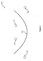
- FIG. 3 A cross-sectional view of one such alternative apparatus for detecting magnetic resonance signals 101 is illustrated in Figure 3 .
- the apparatus also comprises a magnetic resonance sensor 111, a shield member 131 and a magnetic resonator 151.
- the shield member 131 is also dish-shaped but the concavity of the shield member 131 is much greater than the embodiment shown in Figure 2 .
- the diameter of the magnetic resonance sensor 111 is smaller than the diameter of the rim of the shield member 131.
- the magnetic resonance sensor 111 is positioned relative to the shield member 131 such that the shield member 131 encompasses the magnetic resonance sensor 111.
- the diameter of the magnetic resonator 151 is in excess of the diameter of the rim of the shield member 131.
- the magnetic resonator 151 is positioned relative to the shield member 131 such that the magnetic resonator 151 encircles the shield member 131.
- the apparatus 100, 101 is capable of detecting magnetic resonance signals even in the presence of magnetic fields originating from distant transmitters or nearby mains wiring.
- the magnetic resonance sensor can be formed from a single loop having a diameter of 108mm
- the shield member can be bowl shaped and have a diameter of 136mm
- the magnetic resonator can be a ribbon having a diameter of 160mm. The elements are arranged such that the total stacked height is 59mm.
- Figure 4 is a block diagram illustrating the circuit components of the embodiment of the apparatus which shows the components which are used to reduce electric coupling. Figure 4 does not show the shield member 130 or the magnetic resonator as these are not electrically coupled to the MR sensor 110.
- the circuit equivalent of the physical magnetic sensor 110 is the magnetic resonance sensor circuit 210.
- the apparatus 100 comprises a magnetic resonance sensor circuit 210 adapted to respond to magnetic resonance signals, an output 250, an isolation circuit 230 arranged between the magnetic resonance sensor circuit 210 and the output 250 to transfer electrical energy from the magnetic resonance sensor circuit 210 to the output 250 while reducing electrical energy electrically coupled to the magnetic resonance sensor circuit 210 from transferring to the output 250, and a compensation circuit 280 connected to the isolation circuit 230 and the output 250 to compensate for electrical energy due to electric coupling within the isolation circuit 230.
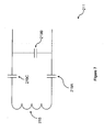
- FIG. 5 An exemplary circuit diagram of the apparatus 100 is illustrated in Figure 5 .
- FIG. 6 A detailed view of the isolation circuit 230 of the apparatus 100 is shown in Figure 6 .
- the magnetic resonance sensor circuit 210 comprises an inductive coil 214 connected to a matching network for tunning the coil.
- the inductive coil may also be a single turn circular loop having high symmetry.
- the matching network comprises a capacitor 218.
- the matching network may comprise different elements depending on the desired operating characteristics such as the desired magnetic resonance operating frequency. Regardless of the number of elements in the matching network, it is advantageous if the elements are approximately balanced between each side of the inductive coil 214 - i.e. highly symmetrical.
- the isolation circuit 230 is an isolation transformer.
- a detailed view of the isolation circuit 230 is provided in Figure 6 which shows that the primary winding 234 of the isolation transformer is connected to the matching network 218.
- the secondary winding 238 of the isolation transformer is connected to the output 250 and referenced to ground.
- the secondary winding may be referenced to any system voltage and that the isolation transformer may also serve the purpose of impedance matching transformation.
- the isolation transformer acts to electrically "float" the active elements of the magnetic resonance sensor circuit 210 (that is, the inductive coil 214 and the matching network 218).
- the primary winding 234 of the transformer floats with these elements.
- the magnetic resonance sensor circuit 210 and primary winding 234 can rise to a voltage that can prevent current flow between the magnetic resonance sensor circuit 210 and external voltage sources.
- the isolation imparted by the isolation transformer reduces the amount of this voltage (or prevents portion of this voltage) from appearing at the output 250.
- the compensation circuit 280 illustrated in Figure 5 comprises a capacitor 288 and a voltage inverting circuit 284 connected to the capacitor.
- the capacitor 288 is connected via a halfway tap 236 connected halfway along the length of the primary winding 234 of the isolation transformer 230. (In practical terms, this capacitor may not tap the primary winding 234 of the isolation transformer at a point exactly halfway along its length while still acting adequately to provide compensation.)
- the capacitance value of the capacitor 288 can be set to minimize any voltage due to electric coupling at the output.
- the voltage inverting circuit 284 is a 1:1 impedance ratio transformer with counter-fed windings which is connected directly to the output. Persons skilled in the art will appreciate that other voltage inverting devices can be used for example, an amplifier circuit.
- the compensation circuit 280 compensates for imperfect isolation between the primary and secondary windings 234,238 of the isolation transformer because of interwinding capacitance. Specifically, the compensation circuit 280 compensates for imperfect isolation by reducing common mode currents transmitted through the transformer. In this embodiment, if the current through the capacitor 288 connected to the halfway tap 236 has similar magnitude to that in the interwinding capacitance, then cancellation of additional unwanted common mode voltage at the output can occur. It is envisaged that other compensation or "neutralisation” techniques can also be used to similarly limit the effect of common mode current on the output. Further it will be appreciated that some advantage is obtained by using the isolation circuit without the compensation circuit.
- FIG. 7 is a circuit diagram of an alternative MR resonance sensor 211.
- the MR resonance sensor 211 comprises an inductive coil 215 and capacitors 219A,219B,219C arranged symmetrically relative to the inductive coil 215.
- the inductive coil 215 is a multi-turn coil.
- a circular single turn loop or any design having high symmetry and low impedance to allow for a simple tuning design and low sensitivity to field gradients can also be used.
- an embodiment of the present application can be used in a wide variety of applications.
- an embodiment can be used to detect specific minerals in bulk material in open plant environments (such as conveyors, slurry systems, boreholes or rock faces), detect narcotics and explosives carried on humans or in parcels in real-time, and measure and characterize materials in laboratories to investigate bonding and molecular structure.
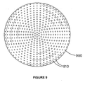
- the shield member has some perforations to increase the magnetic coupling between the magnetic resonance sensor and the magnetic resonator.
- the control of the coupling by this mechanism allows variation in the spacing between elements of the apparatus, leading to improved sensitivity with judicious spacing of elements.
- the perforations may take the form of circular holes or holes of other shape to allow additional magnetic flux to thread both the magnetic resonance sensor and magnetic resonator, thereby modifying the coupling between these elements.
- the spacing of holes may be arranged regularly in the form of a mesh.
- the holes may also be arranged in an array.
- Figure 9 shows an example of embodiment where the shield member 900 contains perforations 910. Depending on the embodiment, the perforations may cover up to 50% of the surface area.
- a sieve type mesh is possible, but meshes may be employed where the conducting elements are flattened and present a larger area than what is normally associated with a sieve.
- the mesh may be formed of conducting elements carried by a supporting material, such as by being woven into a fabric. In practice a bonded-type mesh (where metal crossovers have physical bonding rather than just touching) is the most advantageous.
- the above apparatus is modified to provide for the mitigation of the effects of asymmetrically applied voltages across the magnetic resonance sensor.
- Asymmetric voltages may occur, for example, when positioning one side of the sensor in closer proximity to a voltage disturbance than the other side of the sensor.
- the asymmetric voltage distribution may drive unequal currents through the isolation circuit, giving rise to an apparent magnetic resonance signal.
- multiple floating electrodes i.e., electrodes that make no physical contact with either the magnetic resonance sensor, shield member or magnetic resonator
- a symmetry axis exists through the midline of the magnetic resonance sensor 110, defined through the centre of the isolation circuit 115 and the opposing point on the magnetic resonance sensor which is shown as line A-A in Figures 10A and 11A . Electrodes that are oppositely disposed to each other with reference to this line of symmetry are joined to each other by conducting wires or ribbons.
- Figures 10A and 10B show an embodiment, where wires 165 joining the oppositely opposed electrodes 168 run across the aperture 180 of the magnetic resonance sensor 110.
- Figures 11A and 11B show an alternative embodiment, where the electrodes 160 are linked sequentially by thin wires 170 along the edge of the sensor 110.
- the wire diameter must be small compared to the minor radius of the magnetic resonance sensor.
- a combination of wires run across the aperture and segments of wire joining consecutive electrodes to enable formation of an equipotential across the multi-electrode structure.
- the capacitance between each electrode and the magnetic resonance sensor is large compared to the capacitance between the electrode and the disturbing voltage source.
- the impedance of the wires joining the electrodes is small compared to the electrode-sensor capacitance.
- conductively joined electrodes essentially act as one single equipotential. Since electrodes are joined across the axis of symmetry, the electrodes act to provide a symmetrised voltage distribution across the magnetic resonance sensor. This symmetric voltage distribution is subsequently rejected by the isolation circuit and compensation circuit (in embodiments employing a compensation circuit).
- the multiple electrodes cannot be replaced with one single floating electrode; it is important to maintain some discontinuity between electrodes.
- the electrodes are made of conducting material having thickness much less than the material electrical skin depth. This reduces the losses in the electrodes. It is also beneficial if the electrodes are shaped to conform to a surface parallel to the surface of the magnetic resonance sensor. That is, if the surface of the voltage distribution electrode is uniformly spaced from the surface of the magnetic resonance sensor. This reduces current proximity effects in the electrodes.
- the electrodes are advantageously combined with embodiments simultaneously employing the isolation circuit, and optionally with those also employing a compensation circuit. It will be appreciated that the isolation and compensation circuits do not require the electrode arrangement for useful operation.
Landscapes
- Physics & Mathematics (AREA)
- Condensed Matter Physics & Semiconductors (AREA)
- General Physics & Mathematics (AREA)
- Health & Medical Sciences (AREA)
- Epidemiology (AREA)
- Measuring Magnetic Variables (AREA)
- Magnetic Resonance Imaging Apparatus (AREA)
Claims (15)
- Vorrichtung zum Ermitteln von Magnetresonanzsignalen von einem Target, umfassend:einen Magnetresonanzsensor für Nahfeld-Faraday-Ermittlung von Magnetresonanzsignalen von einem Target durch Reagieren auf die Magnetresonanzsignale, um eine Magnetresonanzsignalspannung auszugeben;ein leitfähiges Abschirmungsteil, das vom Magnetresonanzsensor elektrisch isoliert ist, wobei das Abschirmungsteil schüsselförmig ist, um dadurch eine konkave Seite und eine gegenüberliegende konvexe Seite zu definieren, und relativ zum Magnetresonanzsensor so angeordnet ist, dass sich der Magnetresonanzsensor auf der konkaven Seite des Abschirmungsteils befindet, sodass, wenn der Magnetresonanzsensor dem Target zugewandt ist, das Abschirmungsteil hinter dem Magnetresonanzsensor liegt, um den Magnetresonanzsensor zumindest teilweise von magnetischer Kopplung mit Quellen anderer störender Magnetfelder als der Magnetresonanzsignale abzuschirmen; undeinen auf der konvexen Seite des Abschirmungsteils angeordneten Magnetresonator, wobei der Magnetresonator vom Abschirmungsteil und vom Magnetresonanzsensor elektrisch isoliert ist, wobei der Magnetresonator dafür eingerichtet ist, mit einem Magnetfeld zu schwingen und es zum Target und somit zum Magnetresonanzsensor zu streuen, um dadurch zumindest teilweise die magnetische Kopplung von Quellen anderer störender Magnetfelder als des Targets mit dem Magnetresonanzsensor zu kompensieren.
- Vorrichtung nach Anspruch 1, worin der Magnetresonanzsensor vom Abschirmungsteil umschlossen wird, indem er innerhalb der Wölbung der konkaven Seite des Abschirmungsteils angeordnet ist.
- Vorrichtung nach Anspruch 1 oder 2, worin das Abschirmungsteil vom Magnetresonator umringt wird, indem der Magnetresonator einen größeren Durchmesser als das Abschirmungsteil hat.
- Vorrichtung nach einem der Ansprüche 1 bis 3, worin:der Magnetresonanzsensor ein erstes Abstimmelement zum Abstimmen des Magnetresonanzsensors, damit er ungefähr bei einer vorbestimmten Arbeitsfrequenz arbeitet, umfasst; undder Magnetresonator ein zweites Abstimmelement zum Abstimmen des Magnetresonators auf eine Resonanz unterhalb der vorbestimmten Arbeitsfrequenz umfasst.
- Vorrichtung nach einem der Ansprüche 1 bis 4, worin der Magnetresonanzsensor und der Magnetresonator kreisförmig sind.
- Vorrichtung nach einem der Ansprüche 1 bis 5, worin das Abschirmungsteil eine Vielzahl von Perforationen umfasst.
- Vorrichtung nach einem der Ansprüche 1 bis 6, umfassend:einen Ausgang zum Ausgeben der Magnetresonanzsignalspannung; undeine Trennschaltung, die zwischen dem Magnetresonanzsensor und dem Ausgang angeordnet ist, um elektrische Energie aus der Reaktion des Magnetresonanzsensors auf die Magnetresonanzsignale zum Ausgang zu übertragen, unter Reduzierung der zum Ausgang übertragenen elektrischen Energie, die elektrisch durch störende elektrische Felder zum Magnetresonanzsensor gekoppelt wird.
- Vorrichtung nach Anspruch 7, ferner eine Kompensationsschaltung umfassend, die mit der Trennschaltung und dem Ausgang gekoppelt ist, um elektrische Energie aufgrund elektrischer Kopplung durch störende elektrische Felder innerhalb der Trennschaltung zu kompensieren.
- Vorrichtung nach Anspruch 7 oder 8, worin die Trennschaltung ein Trenntransformator ist.
- Vorrichtung nach Anspruch 9, worin der Trenntransformator umfasst:eine mit dem Magnetresonanzsensor verbundene Primärwindung; undeine mit dem Ausgang verbundene Sekundärwindung, wobei die Sekundärwindung auf eine Systemspannung bezogen wird.
- Vorrichtung nach Anspruch 10, worin die Kompensationsschaltung umfasst:einen mit der Primärwindung des Trenntransformators verbundenen Kondensator; undeine mit dem Kondensator verbundene Spannungsumkehrschaltung.
- Vorrichtung nach einem der Ansprüche 9 bis 11, umfassend mindestens ein Paar von Spannungsverteilungselektroden in unmittelbarer Nähe zum, aber elektrisch isoliert vom Magnetresonanzsensor, wobei jedes Paar von Spannungsverteilungselektroden symmetrisch in Bezug auf eine Symmetrielinie angeordnet ist, die durch eine Mittellinie des Magnetresonanzsensors definiert ist, die sich durch die Trennschaltung erstreckt, wobei die Spannungsverteilungselektroden elektrisch verbunden sind, um die Ausbildung eines Äquipotentials zu ermöglichen.
- Vorrichtung nach Anspruch 12, worin mindestens ein Paar von Spannungsverteilungselektroden durch einen elektrischen Verbinder verbunden ist, der sich über eine Apertur des Magnetresonanzsensors hinweg erstreckt.
- Vorrichtung nach Anspruch 12, worin eine Dicke jeder Spannungsverteilungselektrode kleiner als die elektrische Eindringtiefe eines Materials ist, aus dem jede Spannungsverteilungselektrode gebildet ist.
- Vorrichtung nach Anspruch 12, worin die Oberfläche jeder Spannungsverteilungselektrode gleichmäßig vom Magnetresonanzsensor beabstandet ist.
Applications Claiming Priority (2)
| Application Number | Priority Date | Filing Date | Title |
|---|---|---|---|
| AU2009905897A AU2009905897A0 (en) | 2009-12-02 | An apparatus for detecting signals | |
| PCT/AU2010/001600 WO2011066600A1 (en) | 2009-12-02 | 2010-11-29 | An apparatus for detecting signals |
Publications (3)
| Publication Number | Publication Date |
|---|---|
| EP2510372A1 EP2510372A1 (de) | 2012-10-17 |
| EP2510372A4 EP2510372A4 (de) | 2013-05-22 |
| EP2510372B1 true EP2510372B1 (de) | 2015-07-01 |
Family
ID=44114544
Family Applications (1)
| Application Number | Title | Priority Date | Filing Date |
|---|---|---|---|
| EP10834080.3A Active EP2510372B1 (de) | 2009-12-02 | 2010-11-29 | Vorrichtung zur detektion von magnetresonanzsignalen |
Country Status (7)
| Country | Link |
|---|---|
| US (1) | US9335390B2 (de) |
| EP (1) | EP2510372B1 (de) |
| CN (1) | CN102713655B (de) |
| AU (1) | AU2010327357B2 (de) |
| CL (1) | CL2012001448A1 (de) |
| WO (1) | WO2011066600A1 (de) |
| ZA (1) | ZA201203657B (de) |
Families Citing this family (7)
| Publication number | Priority date | Publication date | Assignee | Title |
|---|---|---|---|---|
| CN104266665B (zh) * | 2014-09-17 | 2016-09-28 | 上海兰宝传感科技股份有限公司 | 电感式传感器 |
| PE20181459A1 (es) | 2015-08-24 | 2018-09-13 | Commw Scient Ind Res Org | Un aparato para la deteccion en linea de senales de resonancia magnetica desde un material objetivo en un lodo mineral |
| BR112018003447B1 (pt) * | 2015-08-24 | 2022-10-25 | Commonwealth Scientific And Industrial Research Organisation | Equipamento e sistema de ressonância magnética para a análise de um material, e método para a determinação da massa de um material alvo em um minério |
| US11307055B2 (en) | 2019-09-18 | 2022-04-19 | Analog Devices International Unlimited Company | Sensor with magnetic shield |
| WO2021127734A1 (en) * | 2019-12-24 | 2021-07-01 | Commonwealth Scientific And Industrial Research Organisation | An apparatus for the measurement of ore in mine haul vehicles |
| US12055502B2 (en) * | 2019-12-24 | 2024-08-06 | Commonwealth Scientific And Industrial Research Organisation | Apparatus for the measurement of ore in mine ore benches |
| KR102623195B1 (ko) * | 2021-11-26 | 2024-01-10 | 대한전선 주식회사 | 전자식 변성기 내장형 가스절연개폐장치용 스페이서 내부에 포함되는 쉴드링 |
Family Cites Families (25)
| Publication number | Priority date | Publication date | Assignee | Title |
|---|---|---|---|---|
| US5594342A (en) * | 1992-06-01 | 1997-01-14 | Conductus, Inc. | Nuclear magnetic resonance probe coil with enhanced current-carrying capability |
| DE4301557C2 (de) * | 1993-01-21 | 1995-07-06 | Siemens Ag | Antennenanordnung mit Abschirmung für ein Kernspintomographiegerät |
| GB9307646D0 (en) * | 1993-04-14 | 1993-06-02 | Marconi Gec Ltd | Electric field screen |
| US6028429A (en) * | 1996-07-17 | 2000-02-22 | Fonar Corporation | Composite MRI antenna with reduced stray capacitance |
| DE19810837C2 (de) | 1998-03-12 | 2002-12-12 | Siemens Ag | Hochfrequenzantenne für ein Magnetresonanzgerät |
| US6249121B1 (en) * | 1999-05-17 | 2001-06-19 | General Electric Company | RF body coil |
| US6498487B1 (en) | 2000-01-25 | 2002-12-24 | Varian, Inc. | Distributed capacitance inserts for NMR probes |
| US6888153B2 (en) | 2000-04-05 | 2005-05-03 | University Of Washington | Capacitive shield for containing radiofrequency magnetic fields |
| US6538442B2 (en) * | 2000-12-22 | 2003-03-25 | Ge Medical Systems Global Technology Company | MRI system having RF shielding gradient coil structure |
| WO2003067267A2 (en) | 2002-02-06 | 2003-08-14 | The Regents Of The University Of California | Squid detected nmr and mri at ultralow fields |
| US6885194B2 (en) * | 2002-05-03 | 2005-04-26 | Ge Medical Systems Global Technology Company, Llc | Method and apparatus for minimizing gradient coil and rf coil coupling |
| US7180950B2 (en) * | 2002-11-01 | 2007-02-20 | Avago Technologies Fiber Ip (Singapore) Pte. Ltd. | Low-noise feedback cancellation filter for enhanced common-mode rejection and noise immunity |
| US6927575B2 (en) * | 2003-01-21 | 2005-08-09 | General Electric Company | Surface coil decoupling means for MRI systems |
| US7250764B2 (en) * | 2003-09-12 | 2007-07-31 | Ge Medical Systems Global Technology Company, Llc | Shielded dome resonator for MR scanning of a cerebrum |
| AR048373A1 (es) * | 2004-07-08 | 2006-04-26 | Spinlock Srl | Un dispositivo y un metodo para medir en forma directa y en tiempo real, la proporcion y el caudal de los distintos componentes que conforman un fluido complejo multicomponente , una disposicion de linea de produccion para un fluido complejo multicomponente que utiliza dicho dispositivo y un metodo |
| US20060084861A1 (en) | 2004-10-18 | 2006-04-20 | Topspin Medical (Isreal) Ltd. | Magnet and coil configurations for MRI probes |
| US7501825B2 (en) | 2005-03-02 | 2009-03-10 | New York University | Magnetic resonance imaging method and system |
| US20070096731A1 (en) * | 2005-11-03 | 2007-05-03 | Rf Sensors, Llc | Open-Shape Noise-Resilient Multi-Frequency Sensors |
| US8013606B2 (en) | 2006-03-22 | 2011-09-06 | Koninklijke Philips Electronics N.V. | Shielded multix coil array for parallel high field MRI |
| US7932721B2 (en) | 2006-04-07 | 2011-04-26 | The United States Of America As Represented By The Department Of Health And Human Services | Inductive decoupling of a RF coil array |
| US7327137B1 (en) * | 2006-11-14 | 2008-02-05 | Ge Homeland Protection, Inc. | Apparatus and method for non-symmetric magnetic field balancing in an inspection scanner |
| EP2620783A1 (de) * | 2007-02-26 | 2013-07-31 | Koninklijke Philips Electronics N.V. | Doppelresonante Hochfeld-Radiofrequenz-Oberflächenspulen für die magnetische Resonanz |
| US7743860B2 (en) | 2007-10-09 | 2010-06-29 | Ford Global Technologies, Llc | Holding a hybrid electric vehicle on an inclined surface |
| JP5247214B2 (ja) * | 2008-04-04 | 2013-07-24 | 株式会社日立製作所 | 高周波磁場コイル及び磁気共鳴撮影装置 |
| US20100073000A1 (en) * | 2008-09-22 | 2010-03-25 | Insight Neuroimaging Systems, Llc | Radio frequency coil apparatus and methods |
-
2010
- 2010-11-29 AU AU2010327357A patent/AU2010327357B2/en active Active
- 2010-11-29 WO PCT/AU2010/001600 patent/WO2011066600A1/en not_active Ceased
- 2010-11-29 CN CN201080061826.9A patent/CN102713655B/zh active Active
- 2010-11-29 US US13/513,443 patent/US9335390B2/en active Active
- 2010-11-29 EP EP10834080.3A patent/EP2510372B1/de active Active
-
2012
- 2012-05-18 ZA ZA2012/03657A patent/ZA201203657B/en unknown
- 2012-06-01 CL CL2012001448A patent/CL2012001448A1/es unknown
Also Published As
| Publication number | Publication date |
|---|---|
| AU2010327357B2 (en) | 2014-09-18 |
| US9335390B2 (en) | 2016-05-10 |
| ZA201203657B (en) | 2013-08-28 |
| US20120242340A1 (en) | 2012-09-27 |
| CL2012001448A1 (es) | 2013-04-12 |
| CN102713655A (zh) | 2012-10-03 |
| WO2011066600A1 (en) | 2011-06-09 |
| EP2510372A4 (de) | 2013-05-22 |
| EP2510372A1 (de) | 2012-10-17 |
| AU2010327357A1 (en) | 2012-06-21 |
| CN102713655B (zh) | 2016-01-20 |
Similar Documents
| Publication | Publication Date | Title |
|---|---|---|
| EP2510372B1 (de) | Vorrichtung zur detektion von magnetresonanzsignalen | |
| US4725779A (en) | NMR local coil with improved decoupling | |
| EP2097763B1 (de) | Rf-spule zur verwendung in einem mr-bildgebungssystem, in kombination mit einem metamaterial | |
| EP3685198B1 (de) | Vorrichtung und verfahren zur fremdkörperdetektion bei drahtloser energieübertragung | |
| EP0047065B1 (de) | Phasenverteilende RF-Spule | |
| US20050146331A1 (en) | Transmit-receive coil system for nuclear quadrupole resonance signal detection in substances and components thereof | |
| GB2063569A (en) | Shielded balanced loop antennas | |
| US10191128B2 (en) | Device and method for loops-over-loops MRI coils | |
| EP0162534B1 (de) | Spulenanordnung | |
| AU2016312967B2 (en) | On-line magnetic resonance measurement of conveyed material | |
| BR102017010197B1 (pt) | Aparelho de detecção de metais | |
| US6870453B2 (en) | MR apparatus provided with an open magnet system and a quadrature coil system | |
| US11280861B2 (en) | Sheath wave barrier for magnetic resonance (MR) applications | |
| US11460599B2 (en) | Shielded-loop-resonator based gradiometer probe | |
| CN114910850B (zh) | 一种双核mri的图像增强超构表面器件 | |
| US20170219667A1 (en) | Planar Standing Wave Trap for a Magnetic Resonance Tomograph | |
| GB2277160A (en) | Electric field screening arrangement for MRI RF coil | |
| EP0502585B1 (de) | Antennenvorrichtung für ein Ladendiebstahldetektierungssystem | |
| Kalagher | An Experimental Study for Determining Optimum Antenna Placement Within a Metallic Enclosure | |
| WO2025172774A1 (en) | Active antenna comprising a single-turn loop aerial | |
| Lee et al. | A nondisturbing electric-field sensor using piezoelectric and converse piezoelectric resonances | |
| GB2522068A (en) | Electric field screening |
Legal Events
| Date | Code | Title | Description |
|---|---|---|---|
| PUAI | Public reference made under article 153(3) epc to a published international application that has entered the european phase |
Free format text: ORIGINAL CODE: 0009012 |
|
| 17P | Request for examination filed |
Effective date: 20120620 |
|
| AK | Designated contracting states |
Kind code of ref document: A1 Designated state(s): AL AT BE BG CH CY CZ DE DK EE ES FI FR GB GR HR HU IE IS IT LI LT LU LV MC MK MT NL NO PL PT RO RS SE SI SK SM TR |
|
| DAX | Request for extension of the european patent (deleted) | ||
| A4 | Supplementary search report drawn up and despatched |
Effective date: 20130419 |
|
| RIC1 | Information provided on ipc code assigned before grant |
Ipc: G01R 33/34 20060101AFI20130415BHEP Ipc: G01R 33/36 20060101ALI20130415BHEP Ipc: G01R 33/422 20060101ALI20130415BHEP |
|
| GRAP | Despatch of communication of intention to grant a patent |
Free format text: ORIGINAL CODE: EPIDOSNIGR1 |
|
| INTG | Intention to grant announced |
Effective date: 20150217 |
|
| GRAS | Grant fee paid |
Free format text: ORIGINAL CODE: EPIDOSNIGR3 |
|
| GRAA | (expected) grant |
Free format text: ORIGINAL CODE: 0009210 |
|
| AK | Designated contracting states |
Kind code of ref document: B1 Designated state(s): AL AT BE BG CH CY CZ DE DK EE ES FI FR GB GR HR HU IE IS IT LI LT LU LV MC MK MT NL NO PL PT RO RS SE SI SK SM TR |
|
| REG | Reference to a national code |
Ref country code: GB Ref legal event code: FG4D |
|
| REG | Reference to a national code |
Ref country code: AT Ref legal event code: REF Ref document number: 734281 Country of ref document: AT Kind code of ref document: T Effective date: 20150715 Ref country code: CH Ref legal event code: EP |
|
| REG | Reference to a national code |
Ref country code: IE Ref legal event code: FG4D |
|
| REG | Reference to a national code |
Ref country code: DE Ref legal event code: R096 Ref document number: 602010025638 Country of ref document: DE |
|
| REG | Reference to a national code |
Ref country code: SE Ref legal event code: TRGR |
|
| REG | Reference to a national code |
Ref country code: AT Ref legal event code: MK05 Ref document number: 734281 Country of ref document: AT Kind code of ref document: T Effective date: 20150701 |
|
| REG | Reference to a national code |
Ref country code: NL Ref legal event code: MP Effective date: 20150701 |
|
| REG | Reference to a national code |
Ref country code: LT Ref legal event code: MG4D |
|
| PG25 | Lapsed in a contracting state [announced via postgrant information from national office to epo] |
Ref country code: LT Free format text: LAPSE BECAUSE OF FAILURE TO SUBMIT A TRANSLATION OF THE DESCRIPTION OR TO PAY THE FEE WITHIN THE PRESCRIBED TIME-LIMIT Effective date: 20150701 Ref country code: LV Free format text: LAPSE BECAUSE OF FAILURE TO SUBMIT A TRANSLATION OF THE DESCRIPTION OR TO PAY THE FEE WITHIN THE PRESCRIBED TIME-LIMIT Effective date: 20150701 Ref country code: NO Free format text: LAPSE BECAUSE OF FAILURE TO SUBMIT A TRANSLATION OF THE DESCRIPTION OR TO PAY THE FEE WITHIN THE PRESCRIBED TIME-LIMIT Effective date: 20151001 Ref country code: GR Free format text: LAPSE BECAUSE OF FAILURE TO SUBMIT A TRANSLATION OF THE DESCRIPTION OR TO PAY THE FEE WITHIN THE PRESCRIBED TIME-LIMIT Effective date: 20151002 |
|
| PG25 | Lapsed in a contracting state [announced via postgrant information from national office to epo] |
Ref country code: ES Free format text: LAPSE BECAUSE OF FAILURE TO SUBMIT A TRANSLATION OF THE DESCRIPTION OR TO PAY THE FEE WITHIN THE PRESCRIBED TIME-LIMIT Effective date: 20150701 Ref country code: RS Free format text: LAPSE BECAUSE OF FAILURE TO SUBMIT A TRANSLATION OF THE DESCRIPTION OR TO PAY THE FEE WITHIN THE PRESCRIBED TIME-LIMIT Effective date: 20150701 Ref country code: IS Free format text: LAPSE BECAUSE OF FAILURE TO SUBMIT A TRANSLATION OF THE DESCRIPTION OR TO PAY THE FEE WITHIN THE PRESCRIBED TIME-LIMIT Effective date: 20151101 Ref country code: PT Free format text: LAPSE BECAUSE OF FAILURE TO SUBMIT A TRANSLATION OF THE DESCRIPTION OR TO PAY THE FEE WITHIN THE PRESCRIBED TIME-LIMIT Effective date: 20151102 Ref country code: HR Free format text: LAPSE BECAUSE OF FAILURE TO SUBMIT A TRANSLATION OF THE DESCRIPTION OR TO PAY THE FEE WITHIN THE PRESCRIBED TIME-LIMIT Effective date: 20150701 Ref country code: AT Free format text: LAPSE BECAUSE OF FAILURE TO SUBMIT A TRANSLATION OF THE DESCRIPTION OR TO PAY THE FEE WITHIN THE PRESCRIBED TIME-LIMIT Effective date: 20150701 Ref country code: PL Free format text: LAPSE BECAUSE OF FAILURE TO SUBMIT A TRANSLATION OF THE DESCRIPTION OR TO PAY THE FEE WITHIN THE PRESCRIBED TIME-LIMIT Effective date: 20150701 |
|
| REG | Reference to a national code |
Ref country code: DE Ref legal event code: R097 Ref document number: 602010025638 Country of ref document: DE |
|
| PG25 | Lapsed in a contracting state [announced via postgrant information from national office to epo] |
Ref country code: IT Free format text: LAPSE BECAUSE OF FAILURE TO SUBMIT A TRANSLATION OF THE DESCRIPTION OR TO PAY THE FEE WITHIN THE PRESCRIBED TIME-LIMIT Effective date: 20150701 Ref country code: SK Free format text: LAPSE BECAUSE OF FAILURE TO SUBMIT A TRANSLATION OF THE DESCRIPTION OR TO PAY THE FEE WITHIN THE PRESCRIBED TIME-LIMIT Effective date: 20150701 Ref country code: EE Free format text: LAPSE BECAUSE OF FAILURE TO SUBMIT A TRANSLATION OF THE DESCRIPTION OR TO PAY THE FEE WITHIN THE PRESCRIBED TIME-LIMIT Effective date: 20150701 Ref country code: CZ Free format text: LAPSE BECAUSE OF FAILURE TO SUBMIT A TRANSLATION OF THE DESCRIPTION OR TO PAY THE FEE WITHIN THE PRESCRIBED TIME-LIMIT Effective date: 20150701 Ref country code: DK Free format text: LAPSE BECAUSE OF FAILURE TO SUBMIT A TRANSLATION OF THE DESCRIPTION OR TO PAY THE FEE WITHIN THE PRESCRIBED TIME-LIMIT Effective date: 20150701 |
|
| PLBE | No opposition filed within time limit |
Free format text: ORIGINAL CODE: 0009261 |
|
| STAA | Information on the status of an ep patent application or granted ep patent |
Free format text: STATUS: NO OPPOSITION FILED WITHIN TIME LIMIT |
|
| PG25 | Lapsed in a contracting state [announced via postgrant information from national office to epo] |
Ref country code: RO Free format text: LAPSE BECAUSE OF FAILURE TO SUBMIT A TRANSLATION OF THE DESCRIPTION OR TO PAY THE FEE WITHIN THE PRESCRIBED TIME-LIMIT Effective date: 20150701 |
|
| 26N | No opposition filed |
Effective date: 20160404 |
|
| PG25 | Lapsed in a contracting state [announced via postgrant information from national office to epo] |
Ref country code: LU Free format text: LAPSE BECAUSE OF FAILURE TO SUBMIT A TRANSLATION OF THE DESCRIPTION OR TO PAY THE FEE WITHIN THE PRESCRIBED TIME-LIMIT Effective date: 20151129 Ref country code: MC Free format text: LAPSE BECAUSE OF FAILURE TO SUBMIT A TRANSLATION OF THE DESCRIPTION OR TO PAY THE FEE WITHIN THE PRESCRIBED TIME-LIMIT Effective date: 20150701 |
|
| REG | Reference to a national code |
Ref country code: CH Ref legal event code: PL |
|
| PG25 | Lapsed in a contracting state [announced via postgrant information from national office to epo] |
Ref country code: LI Free format text: LAPSE BECAUSE OF NON-PAYMENT OF DUE FEES Effective date: 20151130 Ref country code: CH Free format text: LAPSE BECAUSE OF NON-PAYMENT OF DUE FEES Effective date: 20151130 |
|
| REG | Reference to a national code |
Ref country code: IE Ref legal event code: MM4A |
|
| REG | Reference to a national code |
Ref country code: FR Ref legal event code: ST Effective date: 20160729 |
|
| PG25 | Lapsed in a contracting state [announced via postgrant information from national office to epo] |
Ref country code: SI Free format text: LAPSE BECAUSE OF FAILURE TO SUBMIT A TRANSLATION OF THE DESCRIPTION OR TO PAY THE FEE WITHIN THE PRESCRIBED TIME-LIMIT Effective date: 20150701 |
|
| PG25 | Lapsed in a contracting state [announced via postgrant information from national office to epo] |
Ref country code: IE Free format text: LAPSE BECAUSE OF NON-PAYMENT OF DUE FEES Effective date: 20151129 |
|
| PG25 | Lapsed in a contracting state [announced via postgrant information from national office to epo] |
Ref country code: FR Free format text: LAPSE BECAUSE OF NON-PAYMENT OF DUE FEES Effective date: 20151130 |
|
| PG25 | Lapsed in a contracting state [announced via postgrant information from national office to epo] |
Ref country code: BE Free format text: LAPSE BECAUSE OF FAILURE TO SUBMIT A TRANSLATION OF THE DESCRIPTION OR TO PAY THE FEE WITHIN THE PRESCRIBED TIME-LIMIT Effective date: 20150701 |
|
| PG25 | Lapsed in a contracting state [announced via postgrant information from national office to epo] |
Ref country code: BG Free format text: LAPSE BECAUSE OF FAILURE TO SUBMIT A TRANSLATION OF THE DESCRIPTION OR TO PAY THE FEE WITHIN THE PRESCRIBED TIME-LIMIT Effective date: 20150701 Ref country code: SM Free format text: LAPSE BECAUSE OF FAILURE TO SUBMIT A TRANSLATION OF THE DESCRIPTION OR TO PAY THE FEE WITHIN THE PRESCRIBED TIME-LIMIT Effective date: 20150701 Ref country code: HU Free format text: LAPSE BECAUSE OF FAILURE TO SUBMIT A TRANSLATION OF THE DESCRIPTION OR TO PAY THE FEE WITHIN THE PRESCRIBED TIME-LIMIT; INVALID AB INITIO Effective date: 20101129 |
|
| PG25 | Lapsed in a contracting state [announced via postgrant information from national office to epo] |
Ref country code: CY Free format text: LAPSE BECAUSE OF FAILURE TO SUBMIT A TRANSLATION OF THE DESCRIPTION OR TO PAY THE FEE WITHIN THE PRESCRIBED TIME-LIMIT Effective date: 20150701 Ref country code: NL Free format text: LAPSE BECAUSE OF FAILURE TO SUBMIT A TRANSLATION OF THE DESCRIPTION OR TO PAY THE FEE WITHIN THE PRESCRIBED TIME-LIMIT Effective date: 20150701 |
|
| PG25 | Lapsed in a contracting state [announced via postgrant information from national office to epo] |
Ref country code: MT Free format text: LAPSE BECAUSE OF FAILURE TO SUBMIT A TRANSLATION OF THE DESCRIPTION OR TO PAY THE FEE WITHIN THE PRESCRIBED TIME-LIMIT Effective date: 20150701 |
|
| PG25 | Lapsed in a contracting state [announced via postgrant information from national office to epo] |
Ref country code: TR Free format text: LAPSE BECAUSE OF FAILURE TO SUBMIT A TRANSLATION OF THE DESCRIPTION OR TO PAY THE FEE WITHIN THE PRESCRIBED TIME-LIMIT Effective date: 20150701 Ref country code: MK Free format text: LAPSE BECAUSE OF FAILURE TO SUBMIT A TRANSLATION OF THE DESCRIPTION OR TO PAY THE FEE WITHIN THE PRESCRIBED TIME-LIMIT Effective date: 20150701 |
|
| PG25 | Lapsed in a contracting state [announced via postgrant information from national office to epo] |
Ref country code: AL Free format text: LAPSE BECAUSE OF FAILURE TO SUBMIT A TRANSLATION OF THE DESCRIPTION OR TO PAY THE FEE WITHIN THE PRESCRIBED TIME-LIMIT Effective date: 20150701 |
|
| P01 | Opt-out of the competence of the unified patent court (upc) registered |
Effective date: 20230524 |
|
| PGFP | Annual fee paid to national office [announced via postgrant information from national office to epo] |
Ref country code: DE Payment date: 20251118 Year of fee payment: 16 |
|
| PGFP | Annual fee paid to national office [announced via postgrant information from national office to epo] |
Ref country code: GB Payment date: 20251124 Year of fee payment: 16 |
|
| PGFP | Annual fee paid to national office [announced via postgrant information from national office to epo] |
Ref country code: FI Payment date: 20251118 Year of fee payment: 16 |
|
| PGFP | Annual fee paid to national office [announced via postgrant information from national office to epo] |
Ref country code: SE Payment date: 20251119 Year of fee payment: 16 |