EP2510522B1 - Agencement de grille non parallèle avec étagement de phases à la volée et système de rayons x - Google Patents
Agencement de grille non parallèle avec étagement de phases à la volée et système de rayons x Download PDFInfo
- Publication number
- EP2510522B1 EP2510522B1 EP10796148.4A EP10796148A EP2510522B1 EP 2510522 B1 EP2510522 B1 EP 2510522B1 EP 10796148 A EP10796148 A EP 10796148A EP 2510522 B1 EP2510522 B1 EP 2510522B1
- Authority
- EP
- European Patent Office
- Prior art keywords
- grating
- ray
- grating element
- ray system
- phase
- Prior art date
- Legal status (The legal status is an assumption and is not a legal conclusion. Google has not performed a legal analysis and makes no representation as to the accuracy of the status listed.)
- Active
Links
Images



Classifications
-
- G—PHYSICS
- G21—NUCLEAR PHYSICS; NUCLEAR ENGINEERING
- G21K—HANDLING OF PARTICLES OR IONISING RADIATION NOT OTHERWISE PROVIDED FOR; IRRADIATION DEVICES; GAMMA RAY OR X-RAY MICROSCOPES
- G21K1/00—Arrangements for handling particles or ionising radiation, e.g. focusing or moderating
- G21K1/06—Arrangements for handling particles or ionising radiation, e.g. focusing or moderating using diffraction, refraction or reflection, e.g. monochromators
-
- A—HUMAN NECESSITIES
- A61—MEDICAL OR VETERINARY SCIENCE; HYGIENE
- A61B—DIAGNOSIS; SURGERY; IDENTIFICATION
- A61B6/00—Apparatus or devices for radiation diagnosis; Apparatus or devices for radiation diagnosis combined with radiation therapy equipment
- A61B6/48—Diagnostic techniques
- A61B6/484—Diagnostic techniques involving phase contrast X-ray imaging
-
- G—PHYSICS
- G21—NUCLEAR PHYSICS; NUCLEAR ENGINEERING
- G21K—HANDLING OF PARTICLES OR IONISING RADIATION NOT OTHERWISE PROVIDED FOR; IRRADIATION DEVICES; GAMMA RAY OR X-RAY MICROSCOPES
- G21K2201/00—Arrangements for handling radiation or particles
- G21K2201/06—Arrangements for handling radiation or particles using diffractive, refractive or reflecting elements
-
- G—PHYSICS
- G21—NUCLEAR PHYSICS; NUCLEAR ENGINEERING
- G21K—HANDLING OF PARTICLES OR IONISING RADIATION NOT OTHERWISE PROVIDED FOR; IRRADIATION DEVICES; GAMMA RAY OR X-RAY MICROSCOPES
- G21K2207/00—Particular details of imaging devices or methods using ionizing electromagnetic radiation such as X-rays or gamma rays
- G21K2207/005—Methods and devices obtaining contrast from non-absorbing interaction of the radiation with matter, e.g. phase contrast
Definitions
- the present invention relates to X-ray image acquisition in general. More particularly, the present invention relates to image acquisition employing phase-contrast. In particular, the present invention relates to a grating arrangement for phase-contrast imaging, an X-ray system (see also EP1731099 , WO2009/115966 , or EP2478842 , the publication date of EP2478842 being after the filing date of the present application).
- an object to be examined e.g. a patient
- an X-ray generating device or X-ray source e.g. an X-ray tube
- an X-ray detector e.g. an X-ray detector
- a fan-beam or cone-beam is generated by the X-ray source, possibly employing collimation elements, in the direction of the X-ray detector.
- the object to be examined situated in the path of the X-radiation is spatially attenuating the X-ray beam, depending on its inner structure. The spatially attenuated X-radiation is subsequently arriving at the X-ray detector, with the intensity distribution of the X-radiation being determined and subsequently converted to electrical signals for further processing and display of an X-ray image.
- Both the X-ray generating device and the X-ray detector may be mounted on a gantry for rotation about the object to be examined.
- a three-dimensional reconstruction of the objects inner morphology may be obtained.
- a certain object may have only a minor attenuation of X-radiation or differences in attenuation even within different tissues in the inside of the object, thus resulting in a rather uniformly attenuated X-ray image having low contrast and so impeding distinguishing individual elements of the interior of the object to be examined. While different regions within the object may have similar attenuation properties, they may influence a phase of X-radiation penetrating the object to a larger extent.
- phase-contrast imaging may be employed for visualization of phase information of X-radiation, in particular, at least partly, coherent X-rays, passing an object to be examined.
- phase-contrast imaging may not only determine absorption properties of an object to be examined along a projection line, but also the phase-shift of transmitted X-rays.
- a detected phase-shift may thus provide additional information that may be employed for contrast enhancement, determining a material composition, possibly resulting in a reduction in X-radiation dosage.
- phase-shift into an intensity modulation by interference of two or more waves may be employed.
- the use of a cone-beam geometry may constitute a limitation of the usable size of an X-ray detector element, in particular when the phase and/or the absorption gratings are aligned with their trenches parallel to the optical axis.
- the point where the phase-sensitivity drops significantly with respect to the central region of the imaging system is about +-3cm off the optical axis.
- This limitation may in particular depend on grating properties, visibility, distance and angle of a cone beam or fan beam.
- a field of view of fewer than 6 cm, at least in one direction of a two-dimensional X-ray image may be too small to be feasibly reasonable.
- phase contrast imaging multiple images of a region have to be acquired, having individual phase stepping states for a preferred reconstruction of image information.
- the present invention consists in an X-ray system as defined by claim 1.
- FIGs. 1a-c an apparatus for phase-contrast imaging is depicted.
- Fig. 1a shows a three-dimensional representation of an apparatus for phase-contrast imaging.
- a rather large X-ray source 2 is arranged adjacent to a source grating 4. Since X-ray source 2 may be considered to be incoherent due to its size with respect to the wavelength of the radiation emitted, the source grating G 0 4 is employed for providing a plurality of single coherent X-ray sources as depicted by the two arrows in Fig. 1b .
- X-radiation 5 is emanating from X-ray source 2 in the direction of the optical axis 7 possibly constituting a fan-beam or cone-beam of X-rays.
- the respective shape of the X-ray beam is not depicted in Fig. 1a .
- X-radiation 5 is arriving at object 6, penetrating object 6, subsequently arriving at a beam splitter grating G 1 8.
- the trenches or gaps of the beam splitter grating 8 alter the phase of passing electromagnetic radiation with respect to the solid areas of the beam splitter grating, the barrier regions. Accordingly, a phase shift by ⁇ , in particular by ⁇ , is performed.
- An attenuation of X-radiation passing the barrier region compared to X-radiation passing the trench region may be neglectable.
- a source grating 4 may have a grating period of 50 to 200 ⁇ m, e.g. 57 ⁇ m, and may be made of a silicon substrate having a grating structure made e.g. from gold (Au).
- a beam splitter grating 8 may have a grating period of 4 ⁇ m and may be made of a silicon substrate having a grating structure made also from silicon, e.g. by an etching process for removing the material to constitute a trench structure.
- a analyser grating 10 may have a grating period of 2 ⁇ m and may be made of a silicon substrate having a grating structure made also from silicon, e.g. by an etching process for removing the material to constitute a trench structure, with the gaps or trenches filled with a high-z material, e.g. gold (Au).
- An analyzer grating 10 G 2 is arranged between the beam splitter grating G 1 8 and the X-ray detector 12.
- the distance between the source grating and the beam splitter grating 8 is depicted as 1 whereas the distance between the beam splitter grating 8 and the analyzer grating 10 is depicted as distance d.
- the multiple waves originating from the beam splitter grating 8 G 1 in the direction of the X-ray detector are arriving at the analyzer grating 10 G 2 , subsequently producing an intensity modulation pattern (see Fig. 2 ) on the surface of the X-ray detector 12.
- a plurality of intensity modulations induced by the phase stepping may be obtainable by the image detector 12, since the individual phase stepping states are different between individual phase steppings, i.e. alignment of G 1 versus G 2 . Accordingly, by a plurality of Moire patterns, an X-ray image of the object to be examined may be generated.
- Distance 1 may be of the order of 50 - 150cm, e.g.
- distance d may be of the order of 2 - 20cm, depending on the Talbot order chosen in the design of the interferometer, radiation energy and the grating pitch.
- the first fractional Talbot distance is in the order of 50 mm for 17 keV radiation energy or 120mm for 25 keV radiation energy.
- Higher orders of the Talbot distance, e.g. n 3,5,7, are integer multiplies of these distances.
- Gratings G 0 and G 2 may in particular be filled with gold (Au).
- Gratings G 1 and G 2 may be implemented by etching a silicon based material for providing the trenches of the gratings.
- the grating period p 0 of the source grating may be in the order of 200 ⁇ m, even smaller, the grating period p 1 of G 1 may exemplary be in the range of 2 to 6 ⁇ m, in particular 4 ⁇ m and the grating period p 2 of G 2 may exemplary be in the range of 1 to 3 ⁇ m, in particular 2 ⁇ m.
- FIG. 2 an interference pattern is depicted.
- Fig. 2 depicts an interference pattern created between beam splitter grating G 1 8 and analyzer grating G 2 10, demonstrating the self imaging effect of the grid in characteristic distances d 1 , d 2 and d 3 (Talbot effect).
- the relative position of the minima and maxima may in particular depend on the phase-shift of the wave front incident on beam splitter grating G 1 .
- d 1 may in particular be in the order of several cm. If a monochromatic plane wave is incident on the beam-splitter grating that induces a phase shift of ⁇ , in particular by ⁇ , the intensity is split into two main diffraction orders, cancelling the zeroth order.
- the interference effects lead to an effect of self-imaging of the wave-front incident on G 1 at discrete distances downstream from G 1 .
- This effect is referred to as the Talbot effect.
- the phase modulation of the incident wave-front induced by G 1 is transformed into an intensity modulation with double frequency.
- the analyzer grating samples these modulations and allows to measure the phase-gradient induced by an object onto the x-ray wave-front via phase-stepping.
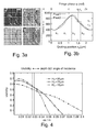
- exemplary phase-contrast images are depicted.
- exemplary four images are acquired of an object comprising individual bubbles by phase stepping employing four phase steps and thus four individual phase stepping states a-d.
- Distances x 1 -x 4 relate to a displacement of grids G 1 versus G 2 for creating an intensity modulation.
- the full movement from x 1 -x 4 is within one period of grating G 2 ( ⁇ 2 ⁇ m).
- the absorber grid or analyzer grid G 2 10 is shifted in a direction x parallel to the grating planes.
- the difference in the wave front phase at two positions "1" and "2" may be extracted from the phase-shift ⁇ 1 - ⁇ 2 of the measured intensity modulation, e.g. for four sampling positions x 1 -x 4 in Fig. 3a .
- FIG. 4 exemplary visibility of interference fringes versus off axis position of a detector element pixel is depicted.
- the degradation of the fringe visibility as a function of the off axis position of detector pixels may be taken from Fig. 4 .
- a fringe visibility of .5 or greater may be considered to provide reasonable phase-contrast for image generation and processing.
- Three functions are provided in Fig. 4 , depending on the height H 2 of the grating structure of grating G 2 (see Fig. 1c ) providing deeper trenches in the grating, e.g. 35 ⁇ m, results in a diminished off axis visibility over a shallower grating depth H 2 of e.g. 15 ⁇ m.
- Fig. 4 As may be taken from Fig.
- a two-sided collimation has to be below 6 cm, thus ⁇ x should be ⁇ 3 cm, thereby limiting the usable size of planar detectors in phase-contrast imaging like e.g. differential phase-contrast mammography, to about 6 cm.
- FIGs. 5a,b an embodiment of a grating arrangement having an X-ray detector element according to the present invention is depicted.
- a first grating element e.g. a beam splitter grating 8 and a second grating element, e.g. an analyzer grating 10 are arranged substantially parallel to one another and to an X-ray detector element 12.
- Each of the source grating 8 and the analyzer grating 10 comprises a base substrate 11, on which individual barrier regions 3 are arranged. Between barrier regions 3, trench regions 9 are arranged. The succession of barrier regions 3 and trench regions 9 constitute the trench structure or grating structure of the grating elements 8, 10.
- the trench structure of the analyzer grating 10 is exemplarily angled relative to the grating structure of the beam splitter grating 8 and the X-ray detector element array arrangement.
- the trench structure of the analyzer grating 10 is parallel to the array structure of the X-ray detector element with the beam splitter grating 8 being tilted by angle ⁇ .
- X-radiation 5 is depicted exemplarily as a cone-beam emanating from X-ray source 2 having a focal spot 14.
- An object 6 is arranged in the cone-beam of X-radiation 5, which penetrates object 6 and subsequently arrives at the beam splitter grating 8, analyzer grating 10 and finally at X-ray detector element 12 for generating phase-contrast image information.
- Grating arrangement 1 is displaced in a scanning movement having a scanning or moving direction e.g. in a linear fashion.
- a scanning movement having a scanning or moving direction e.g. in a linear fashion.
- an image having a field of view larger than the size of X-ray detector 12 is obtainable, with an on the fly phase stepping due to the automatically rearranged grating arrangement relation of beam splitter grating 8 and analyzer grating 10, with respect to the X-ray source and the object to be examined 6.
- FIG. 6 a further grating element is depicted.
- the grating element according to Fig 6 is exemplary an analyzer grating 10, in particular in accordance with features as described earlier, however may also be a phase shift grating.
- the grating structure of analyzer grating 10 of Fig. 6 comprises a sectionally discrete trench structure comprising barrier regions 13 and trench regions 19.
- the trench region may in particular be provided with a filling employing a high-z metal, e.g. gold (Au), not separately depicted in Fig. 6 .
- the individual sectional barrier elements, constituting the barrier region 13, are arranged sectionally discrete having an elongation 20 of length.
- the elongation 20 may in particular be in the order of 1, 2, 3, 4, 5, 6, 7, 8 or more detector pixels.
- the individual sectional barrier elements may each be considered to be aligned substantially parallel to the trench structure of a further grating element, e.g. a beam splitter grating 8, not depicted in Fig. 6 .
- Each sectional barrier element is displaced to adjacent sectional barrier elements by an increment, thus, when employing a further grating element, may result in different phase stepping state.
- the grating element of Fig. 6 not only comprises the discrete trench structure as depicted but is additionally angled with respect to a further grating element, as described above.
- the lateral displacement of the sectional barrier elements of Fig. 6 may also comprise a sinusoidal or curved shape.
Landscapes
- Life Sciences & Earth Sciences (AREA)
- Physics & Mathematics (AREA)
- Engineering & Computer Science (AREA)
- Health & Medical Sciences (AREA)
- Medical Informatics (AREA)
- High Energy & Nuclear Physics (AREA)
- Optics & Photonics (AREA)
- Molecular Biology (AREA)
- General Engineering & Computer Science (AREA)
- Nuclear Medicine, Radiotherapy & Molecular Imaging (AREA)
- Spectroscopy & Molecular Physics (AREA)
- Pathology (AREA)
- Radiology & Medical Imaging (AREA)
- Biomedical Technology (AREA)
- Heart & Thoracic Surgery (AREA)
- Biophysics (AREA)
- Surgery (AREA)
- Animal Behavior & Ethology (AREA)
- General Health & Medical Sciences (AREA)
- Public Health (AREA)
- Veterinary Medicine (AREA)
- Apparatus For Radiation Diagnosis (AREA)
- Analysing Materials By The Use Of Radiation (AREA)
Claims (10)
- Système à rayons X comprenant une source de rayons X (2) et un agencement de réseau (1) pour imagerie par contraste de phase ;
ledit agencement de réseau comprenant un premier élément réseau (8), un deuxième élément réseau (10) et un élément détecteur de rayons X (12) possédant une taille de détecteur ;
dans lequel chacun parmi le premier élément réseau (8) et le deuxième élément réseau (10) comprend une structure de tranchée ;
dans lequel la structure de tranchée comprend au moins une région tranchée (9) et au moins une région barrière (3) ;
dans lequel l'au moins une région tranchée (9) et l'au moins une région barrière (3) sont, au moins localement, agencées en parallèle ;
dans lequel le premier élément réseau (8) et le deuxième élément réseau (10) sont agencés de sorte que la structure de tranchée du premier élément réseau (8) et la structure de tranchée du deuxième élément réseau (10) soient, au moins localement, agencées de façon non parallèle ; et
dans lequel l'élément détecteur de rayons X (12) est agencé sensiblement parallèlement à au moins un parmi le premier élément réseau (8) et le deuxième élément réseau (10) ;
dans lequel le premier élément réseau (8) et le deuxième élément réseau (10) sont agencés par-dessus l'élément détecteur de rayons X (12) ;
dans lequel le premier élément réseau (8), le deuxième élément réseau (10) et l'élément détecteur de rayons X (12) sont prévus sous forme de mono-unité compacte possédant des relations définies des éléments individuels les uns par rapport aux autres ;
dans lequel un objet (6) peut être agencé entre la source de rayons X (12) et l'agencement de réseau (1) ;
dans lequel la source de rayons X (12) et l'agencement de réseau (1) sont fonctionnellement couplés de sorte qu'une image par contraste de phase de l'objet (6) puisse être obtenue par l'élément détecteur de rayons X (12) ;
dans lequel le système à rayons X est configuré pour déplacer le premier élément réseau, le deuxième élément réseau et l'élément détecteur de rayons X sous forme de mono-unité dans un mouvement de balayage à travers le champ de vue. - Système à rayons X selon la revendication précédente,
dans lequel le premier élément réseau (8) et le deuxième élément réseau (10) sont agencés sensiblement parallèlement. - Système à rayons X selon l'une des revendications précédentes,
dans lequel le premier élément réseau (8) est prévu sous forme de réseau séparateur de faisceau (8) ; et/ou
dans lequel le deuxième élément réseau (10) est prévu sous forme de réseau analyseur (10). - Système à rayons X selon l'une des revendications précédentes,
dans lequel la structure de tranchée du premier élément réseau (8) et la structure de tranchée du deuxième élément réseau (10) comprennent un angle α ; et
dans lequel α est dans la plage d'approximativement 1° à 0,01°, en particulier 0,1°, 0,2° ou 0,3°. - Système à rayons X selon l'une des revendications précédentes,
dans lequel le système à rayons X possède un champ de vue plus grand que la taille de détecteur et est adapté pour acquérir une image par contraste de phase ; et
dans lequel, par le déplacement de l'agencement de réseau (1), une image par contraste de phase du champ de vue peut être obtenue. - Système à rayons X selon l'une des revendications précédentes,
dans lequel l'élément détecteur de rayons X (12) est adapté pour acquérir une sous-région d'un champ de vue. - Système à rayons X selon l'une des revendications précédentes,
dans lequel l'agencement de réseau (1) est adapté pour balayer un champ de vue. - Système à rayons X selon l'une des revendications précédentes,
dans lequel l'agencement de réseau (1) est déplaçable d'une première position et/ou orientation pour acquérir des premières informations d'image par contraste de phase à une seconde position et/ou orientation pour acquérir des secondes informations par contraste de phase. - Système à rayons X selon l'une des revendications précédentes, comprend en outre un troisième élément réseau (4), en particulier un réseau source (4).
- Système à rayons X selon l'une des revendications précédentes,
dans lequel la source de rayons X (2) et/ou le troisième élément réseau (4) sont déplaçables par rapport à au moins un parmi le premier élément réseau (8), le deuxième élément réseau (10), l'objet (6) et l'élément détecteur de rayons X (12).
Priority Applications (1)
| Application Number | Priority Date | Filing Date | Title |
|---|---|---|---|
| EP10796148.4A EP2510522B1 (fr) | 2009-12-10 | 2010-12-03 | Agencement de grille non parallèle avec étagement de phases à la volée et système de rayons x |
Applications Claiming Priority (3)
| Application Number | Priority Date | Filing Date | Title |
|---|---|---|---|
| EP09178705 | 2009-12-10 | ||
| PCT/IB2010/055562 WO2011070489A1 (fr) | 2009-12-10 | 2010-12-03 | Agencement de grille non parallèle avec étagement de phases à la volée, système de rayons x et utilisation |
| EP10796148.4A EP2510522B1 (fr) | 2009-12-10 | 2010-12-03 | Agencement de grille non parallèle avec étagement de phases à la volée et système de rayons x |
Publications (2)
| Publication Number | Publication Date |
|---|---|
| EP2510522A1 EP2510522A1 (fr) | 2012-10-17 |
| EP2510522B1 true EP2510522B1 (fr) | 2015-12-02 |
Family
ID=43619788
Family Applications (1)
| Application Number | Title | Priority Date | Filing Date |
|---|---|---|---|
| EP10796148.4A Active EP2510522B1 (fr) | 2009-12-10 | 2010-12-03 | Agencement de grille non parallèle avec étagement de phases à la volée et système de rayons x |
Country Status (5)
| Country | Link |
|---|---|
| US (1) | US8848863B2 (fr) |
| EP (1) | EP2510522B1 (fr) |
| JP (1) | JP5789613B2 (fr) |
| CN (1) | CN102656644B (fr) |
| WO (1) | WO2011070489A1 (fr) |
Families Citing this family (30)
| Publication number | Priority date | Publication date | Assignee | Title |
|---|---|---|---|---|
| DE102010017425A1 (de) * | 2010-06-17 | 2011-12-22 | Karlsruher Institut für Technologie | Geneigte Phasengitterstrukturen |
| WO2012052881A1 (fr) * | 2010-10-19 | 2012-04-26 | Koninklijke Philips Electronics N.V. | Imagerie différentielle en contraste de phase |
| EP2630476B1 (fr) * | 2010-10-19 | 2017-12-13 | Koninklijke Philips N.V. | Imagerie différentielle en contraste de phase |
| JP2012143550A (ja) * | 2010-12-20 | 2012-08-02 | Fujifilm Corp | 放射線画像撮影装置および放射線画像取得方法 |
| JP2012157690A (ja) * | 2011-01-14 | 2012-08-23 | Fujifilm Corp | 放射線画像撮影装置および放射線画像検出器 |
| JP5792961B2 (ja) * | 2011-01-25 | 2015-10-14 | キヤノン株式会社 | トールボット干渉計及び撮像方法 |
| US9557280B2 (en) * | 2011-06-01 | 2017-01-31 | Total Sa | X-ray tomography device |
| BR112013030645A2 (pt) | 2011-06-01 | 2016-11-29 | Total Sa | dispositivo de tomografia de rios x |
| CN103648388B (zh) | 2011-07-04 | 2017-05-03 | 皇家飞利浦有限公司 | 相位对比度成像设备 |
| CN104066375B (zh) * | 2012-01-24 | 2017-08-11 | 皇家飞利浦有限公司 | 多方向相衬x射线成像 |
| WO2014137318A1 (fr) * | 2012-03-05 | 2014-09-12 | University Of Rochester | Procédés et appareils pour tdm à faisceau conique à contraste de phase différentiel et tdm à faisceau conique hybride |
| AU2012268876A1 (en) * | 2012-12-24 | 2014-07-10 | Canon Kabushiki Kaisha | Non-linear solution for 2D phase shifting |
| DE102013213244A1 (de) * | 2013-07-05 | 2015-01-08 | Siemens Aktiengesellschaft | Röntgenaufnahmesystem zur hochaufgelösten differentiellen Phasenkontrast-Bildgebung eines Untersuchungsobjekts |
| CN103961129B (zh) * | 2013-09-11 | 2016-03-30 | 梁月强 | 旋转光栅锥形束ct |
| US9895113B2 (en) * | 2013-09-27 | 2018-02-20 | General Electric Company | Systems and methods for planar imaging with detectors having moving detector heads |
| DE102013219553A1 (de) | 2013-09-27 | 2015-04-02 | Friedrich-Alexander-Universität Erlangen-Nürnberg | Untersuchungsverfahren eines Objekts mit einem Röntgenaufnahmesystem zur Phasenkontrast-Bildgebung mit stochastischer Phasenabtastung |
| DE102013219554A1 (de) * | 2013-09-27 | 2015-04-02 | Friedrich-Alexander-Universität Erlangen-Nürnberg | Untersuchungsverfahren eines Objekts mit einem Röntgenaufnahmesystem zur Phasenkontrast-Bildgebung mit Verschiebungsmessung |
| AU2013260650B2 (en) * | 2013-11-20 | 2015-07-16 | Canon Kabushiki Kaisha | Rotational phase unwrapping |
| JP6667215B2 (ja) * | 2014-07-24 | 2020-03-18 | キヤノン株式会社 | X線遮蔽格子、構造体、トールボット干渉計、x線遮蔽格子の製造方法 |
| US9763631B2 (en) | 2014-09-17 | 2017-09-19 | General Electric Company | Systems and methods for imaging plural axial locations |
| WO2016202685A1 (fr) * | 2015-06-15 | 2016-12-22 | Koninklijke Philips N.V. | Agencement de détecteurs en pavés pour tomographie assistée par ordinateur à contraste de phase différentiel |
| JP6604772B2 (ja) * | 2015-08-05 | 2019-11-13 | キヤノン株式会社 | X線トールボット干渉計 |
| JP6422123B2 (ja) * | 2015-08-27 | 2018-11-14 | 国立大学法人東北大学 | 放射線画像生成装置 |
| JP6613988B2 (ja) * | 2016-03-30 | 2019-12-04 | コニカミノルタ株式会社 | 放射線撮影システム |
| EP3469600B1 (fr) * | 2016-06-08 | 2019-10-02 | Koninklijke Philips N.V. | Analyse de grille pour imagerie à contraste de phase et/ou imagerie sur fond noir |
| JP6753342B2 (ja) * | 2017-03-15 | 2020-09-09 | 株式会社島津製作所 | 放射線格子検出器およびx線検査装置 |
| EP3459461A1 (fr) * | 2017-09-25 | 2019-03-27 | Koninklijke Philips N.V. | Balayage de référence d'imagerie à rayons x |
| WO2021046458A1 (fr) * | 2019-09-06 | 2021-03-11 | The Board Of Trustees Of The Leland Stanford Junior University | Réseau d'analyseur à prise unique pour imagerie par rayons x à contraste de phase différentiel et tomographie assistée par ordinateur |
| EP3922179A1 (fr) * | 2020-06-08 | 2021-12-15 | Koninklijke Philips N.V. | Stratégie d'étape pour la compensation des défauts dans l'imagerie dax |
| WO2024201306A2 (fr) * | 2023-03-26 | 2024-10-03 | Nova Measuring Instruments Inc. | Focalisation de rayons x et sélection de longueur d'onde |
Citations (1)
| Publication number | Priority date | Publication date | Assignee | Title |
|---|---|---|---|---|
| EP2478842A1 (fr) * | 2009-09-16 | 2012-07-25 | Konica Minolta Medical & Graphic, Inc. | Dispositif d'imagerie par rayons x, système d'imageries par rayons x, et procédé de génération de clichés radiographiques |
Family Cites Families (8)
| Publication number | Priority date | Publication date | Assignee | Title |
|---|---|---|---|---|
| EP1731099A1 (fr) * | 2005-06-06 | 2006-12-13 | Paul Scherrer Institut | Interféromètre pour l'imagerie et la tomographie à contraste de phase avec une source de rayons X incohérente et polychromatique |
| DE102006015356B4 (de) * | 2006-02-01 | 2016-09-22 | Siemens Healthcare Gmbh | Verfahren zur Erzeugung projektiver und tomographischer Phasenkontrastaufnahmen mit einem Röntgen-System |
| DE102006037256B4 (de) * | 2006-02-01 | 2017-03-30 | Paul Scherer Institut | Fokus-Detektor-Anordnung einer Röntgenapparatur zur Erzeugung projektiver oder tomographischer Phasenkontrastaufnahmen sowie Röntgensystem, Röntgen-C-Bogen-System und Röntgen-CT-System |
| EP1879020A1 (fr) * | 2006-07-12 | 2008-01-16 | Paul Scherrer Institut | Interféromètre par rayons X pour l'imagerie à contraste de phase |
| JP2008200359A (ja) * | 2007-02-21 | 2008-09-04 | Konica Minolta Medical & Graphic Inc | X線撮影システム |
| CN101576515B (zh) * | 2007-11-23 | 2012-07-04 | 同方威视技术股份有限公司 | X射线光栅相衬成像系统及方法 |
| CN101978257B (zh) | 2008-03-19 | 2014-12-17 | 皇家飞利浦电子股份有限公司 | 用于相位衬度成像的旋转x射线装置 |
| JP2012090944A (ja) * | 2010-03-30 | 2012-05-17 | Fujifilm Corp | 放射線撮影システム及び放射線撮影方法 |
-
2010
- 2010-12-03 JP JP2012542661A patent/JP5789613B2/ja active Active
- 2010-12-03 CN CN201080055836.1A patent/CN102656644B/zh not_active Expired - Fee Related
- 2010-12-03 WO PCT/IB2010/055562 patent/WO2011070489A1/fr not_active Ceased
- 2010-12-03 EP EP10796148.4A patent/EP2510522B1/fr active Active
- 2010-12-03 US US13/514,061 patent/US8848863B2/en active Active
Patent Citations (1)
| Publication number | Priority date | Publication date | Assignee | Title |
|---|---|---|---|---|
| EP2478842A1 (fr) * | 2009-09-16 | 2012-07-25 | Konica Minolta Medical & Graphic, Inc. | Dispositif d'imagerie par rayons x, système d'imageries par rayons x, et procédé de génération de clichés radiographiques |
Also Published As
| Publication number | Publication date |
|---|---|
| CN102656644A (zh) | 2012-09-05 |
| CN102656644B (zh) | 2016-11-16 |
| EP2510522A1 (fr) | 2012-10-17 |
| WO2011070489A1 (fr) | 2011-06-16 |
| US8848863B2 (en) | 2014-09-30 |
| US20120236985A1 (en) | 2012-09-20 |
| JP2013513413A (ja) | 2013-04-22 |
| JP5789613B2 (ja) | 2015-10-07 |
Similar Documents
| Publication | Publication Date | Title |
|---|---|---|
| US8848863B2 (en) | Non-parallel grating arrangement with on-the-fly phase stepping, X-ray system | |
| EP2509503B1 (fr) | Appareil destiné à l'imagerie par contraste de phase comprenant un élément détecteur de rayons x mobile, et procédé associé | |
| US10074451B2 (en) | X-ray interferometer | |
| US10352880B2 (en) | Method and apparatus for x-ray microscopy | |
| EP2442722B1 (fr) | Procéde de correction pour imagerie de contraste de phase différentielle | |
| US7639786B2 (en) | X-ray optical transmission grating of a focus-detector arrangement of an X-ray apparatus for generating projective or tomographic phase contrast recordings of a subject | |
| KR101318221B1 (ko) | X선 촬상장치 및 x선 촬상방법 | |
| CN101011257B (zh) | 产生投影或断层造影相位对比图像的焦点-检测器装置 | |
| JP5601909B2 (ja) | X線撮像装置及びこれを用いるx線撮像方法 | |
| US9269469B2 (en) | Arrangement and method for inverse X-ray phase contrast imaging | |
| US20150279497A1 (en) | X-ray imaging apparatus | |
| WO2017213996A1 (fr) | Procédé et appareil de microscopie à rayons x | |
| US20010038680A1 (en) | X-ray phase-contrast medical micro-imaging methods | |
| JP2009195349A (ja) | X線撮像装置、及び、これに用いるx線源 | |
| WO2007125833A1 (fr) | Dispositif de recuperation d'images radiologiques et procede de recuperation d'images radiologiques | |
| US20110064196A1 (en) | X-ray imaging apparatus and method of x-ray imaging | |
| US10470721B2 (en) | Detector and imaging system for X-ray phase contrast tomo-synthesis imaging | |
| JP7281829B2 (ja) | 放射線画像生成装置 | |
| Olivo | Recent patents in x-ray phase contrast imaging |
Legal Events
| Date | Code | Title | Description |
|---|---|---|---|
| PUAI | Public reference made under article 153(3) epc to a published international application that has entered the european phase |
Free format text: ORIGINAL CODE: 0009012 |
|
| 17P | Request for examination filed |
Effective date: 20120710 |
|
| AK | Designated contracting states |
Kind code of ref document: A1 Designated state(s): AL AT BE BG CH CY CZ DE DK EE ES FI FR GB GR HR HU IE IS IT LI LT LU LV MC MK MT NL NO PL PT RO RS SE SI SK SM TR |
|
| DAX | Request for extension of the european patent (deleted) | ||
| 17Q | First examination report despatched |
Effective date: 20130617 |
|
| RAP1 | Party data changed (applicant data changed or rights of an application transferred) |
Owner name: PHILIPS INTELLECTUAL PROPERTY & STANDARDS GMBH Owner name: KONINKLIJKE PHILIPS N.V. |
|
| GRAP | Despatch of communication of intention to grant a patent |
Free format text: ORIGINAL CODE: EPIDOSNIGR1 |
|
| INTG | Intention to grant announced |
Effective date: 20150626 |
|
| GRAS | Grant fee paid |
Free format text: ORIGINAL CODE: EPIDOSNIGR3 |
|
| GRAA | (expected) grant |
Free format text: ORIGINAL CODE: 0009210 |
|
| AK | Designated contracting states |
Kind code of ref document: B1 Designated state(s): AL AT BE BG CH CY CZ DE DK EE ES FI FR GB GR HR HU IE IS IT LI LT LU LV MC MK MT NL NO PL PT RO RS SE SI SK SM TR |
|
| REG | Reference to a national code |
Ref country code: GB Ref legal event code: FG4D |
|
| REG | Reference to a national code |
Ref country code: AT Ref legal event code: REF Ref document number: 763944 Country of ref document: AT Kind code of ref document: T Effective date: 20151215 Ref country code: CH Ref legal event code: EP |
|
| REG | Reference to a national code |
Ref country code: FR Ref legal event code: PLFP Year of fee payment: 6 |
|
| REG | Reference to a national code |
Ref country code: IE Ref legal event code: FG4D |
|
| REG | Reference to a national code |
Ref country code: DE Ref legal event code: R096 Ref document number: 602010029394 Country of ref document: DE |
|
| REG | Reference to a national code |
Ref country code: NL Ref legal event code: MP Effective date: 20160302 |
|
| REG | Reference to a national code |
Ref country code: LT Ref legal event code: MG4D |
|
| REG | Reference to a national code |
Ref country code: AT Ref legal event code: MK05 Ref document number: 763944 Country of ref document: AT Kind code of ref document: T Effective date: 20151202 |
|
| PG25 | Lapsed in a contracting state [announced via postgrant information from national office to epo] |
Ref country code: ES Free format text: LAPSE BECAUSE OF FAILURE TO SUBMIT A TRANSLATION OF THE DESCRIPTION OR TO PAY THE FEE WITHIN THE PRESCRIBED TIME-LIMIT Effective date: 20151202 Ref country code: LT Free format text: LAPSE BECAUSE OF FAILURE TO SUBMIT A TRANSLATION OF THE DESCRIPTION OR TO PAY THE FEE WITHIN THE PRESCRIBED TIME-LIMIT Effective date: 20151202 Ref country code: NO Free format text: LAPSE BECAUSE OF FAILURE TO SUBMIT A TRANSLATION OF THE DESCRIPTION OR TO PAY THE FEE WITHIN THE PRESCRIBED TIME-LIMIT Effective date: 20160302 |
|
| PG25 | Lapsed in a contracting state [announced via postgrant information from national office to epo] |
Ref country code: RS Free format text: LAPSE BECAUSE OF FAILURE TO SUBMIT A TRANSLATION OF THE DESCRIPTION OR TO PAY THE FEE WITHIN THE PRESCRIBED TIME-LIMIT Effective date: 20151202 Ref country code: PL Free format text: LAPSE BECAUSE OF FAILURE TO SUBMIT A TRANSLATION OF THE DESCRIPTION OR TO PAY THE FEE WITHIN THE PRESCRIBED TIME-LIMIT Effective date: 20151202 Ref country code: BE Free format text: LAPSE BECAUSE OF NON-PAYMENT OF DUE FEES Effective date: 20151231 Ref country code: LV Free format text: LAPSE BECAUSE OF FAILURE TO SUBMIT A TRANSLATION OF THE DESCRIPTION OR TO PAY THE FEE WITHIN THE PRESCRIBED TIME-LIMIT Effective date: 20151202 Ref country code: SE Free format text: LAPSE BECAUSE OF FAILURE TO SUBMIT A TRANSLATION OF THE DESCRIPTION OR TO PAY THE FEE WITHIN THE PRESCRIBED TIME-LIMIT Effective date: 20151202 Ref country code: FI Free format text: LAPSE BECAUSE OF FAILURE TO SUBMIT A TRANSLATION OF THE DESCRIPTION OR TO PAY THE FEE WITHIN THE PRESCRIBED TIME-LIMIT Effective date: 20151202 Ref country code: AT Free format text: LAPSE BECAUSE OF FAILURE TO SUBMIT A TRANSLATION OF THE DESCRIPTION OR TO PAY THE FEE WITHIN THE PRESCRIBED TIME-LIMIT Effective date: 20151202 Ref country code: NL Free format text: LAPSE BECAUSE OF FAILURE TO SUBMIT A TRANSLATION OF THE DESCRIPTION OR TO PAY THE FEE WITHIN THE PRESCRIBED TIME-LIMIT Effective date: 20151202 Ref country code: GR Free format text: LAPSE BECAUSE OF FAILURE TO SUBMIT A TRANSLATION OF THE DESCRIPTION OR TO PAY THE FEE WITHIN THE PRESCRIBED TIME-LIMIT Effective date: 20160303 |
|
| PG25 | Lapsed in a contracting state [announced via postgrant information from national office to epo] |
Ref country code: IS Free format text: LAPSE BECAUSE OF FAILURE TO SUBMIT A TRANSLATION OF THE DESCRIPTION OR TO PAY THE FEE WITHIN THE PRESCRIBED TIME-LIMIT Effective date: 20151202 |
|
| PG25 | Lapsed in a contracting state [announced via postgrant information from national office to epo] |
Ref country code: IT Free format text: LAPSE BECAUSE OF FAILURE TO SUBMIT A TRANSLATION OF THE DESCRIPTION OR TO PAY THE FEE WITHIN THE PRESCRIBED TIME-LIMIT Effective date: 20151202 Ref country code: CZ Free format text: LAPSE BECAUSE OF FAILURE TO SUBMIT A TRANSLATION OF THE DESCRIPTION OR TO PAY THE FEE WITHIN THE PRESCRIBED TIME-LIMIT Effective date: 20151202 |
|
| REG | Reference to a national code |
Ref country code: CH Ref legal event code: PL |
|
| PG25 | Lapsed in a contracting state [announced via postgrant information from national office to epo] |
Ref country code: EE Free format text: LAPSE BECAUSE OF FAILURE TO SUBMIT A TRANSLATION OF THE DESCRIPTION OR TO PAY THE FEE WITHIN THE PRESCRIBED TIME-LIMIT Effective date: 20151202 Ref country code: SM Free format text: LAPSE BECAUSE OF FAILURE TO SUBMIT A TRANSLATION OF THE DESCRIPTION OR TO PAY THE FEE WITHIN THE PRESCRIBED TIME-LIMIT Effective date: 20151202 Ref country code: IS Free format text: LAPSE BECAUSE OF FAILURE TO SUBMIT A TRANSLATION OF THE DESCRIPTION OR TO PAY THE FEE WITHIN THE PRESCRIBED TIME-LIMIT Effective date: 20160402 Ref country code: PT Free format text: LAPSE BECAUSE OF FAILURE TO SUBMIT A TRANSLATION OF THE DESCRIPTION OR TO PAY THE FEE WITHIN THE PRESCRIBED TIME-LIMIT Effective date: 20160404 Ref country code: SK Free format text: LAPSE BECAUSE OF FAILURE TO SUBMIT A TRANSLATION OF THE DESCRIPTION OR TO PAY THE FEE WITHIN THE PRESCRIBED TIME-LIMIT Effective date: 20151202 Ref country code: RO Free format text: LAPSE BECAUSE OF FAILURE TO SUBMIT A TRANSLATION OF THE DESCRIPTION OR TO PAY THE FEE WITHIN THE PRESCRIBED TIME-LIMIT Effective date: 20151202 |
|
| REG | Reference to a national code |
Ref country code: DE Ref legal event code: R097 Ref document number: 602010029394 Country of ref document: DE |
|
| REG | Reference to a national code |
Ref country code: IE Ref legal event code: MM4A |
|
| PG25 | Lapsed in a contracting state [announced via postgrant information from national office to epo] |
Ref country code: MC Free format text: LAPSE BECAUSE OF FAILURE TO SUBMIT A TRANSLATION OF THE DESCRIPTION OR TO PAY THE FEE WITHIN THE PRESCRIBED TIME-LIMIT Effective date: 20151202 |
|
| PLBE | No opposition filed within time limit |
Free format text: ORIGINAL CODE: 0009261 |
|
| STAA | Information on the status of an ep patent application or granted ep patent |
Free format text: STATUS: NO OPPOSITION FILED WITHIN TIME LIMIT |
|
| PG25 | Lapsed in a contracting state [announced via postgrant information from national office to epo] |
Ref country code: DK Free format text: LAPSE BECAUSE OF FAILURE TO SUBMIT A TRANSLATION OF THE DESCRIPTION OR TO PAY THE FEE WITHIN THE PRESCRIBED TIME-LIMIT Effective date: 20151202 Ref country code: LI Free format text: LAPSE BECAUSE OF NON-PAYMENT OF DUE FEES Effective date: 20151231 Ref country code: CH Free format text: LAPSE BECAUSE OF NON-PAYMENT OF DUE FEES Effective date: 20151231 Ref country code: IE Free format text: LAPSE BECAUSE OF NON-PAYMENT OF DUE FEES Effective date: 20151203 |
|
| 26N | No opposition filed |
Effective date: 20160905 |
|
| PG25 | Lapsed in a contracting state [announced via postgrant information from national office to epo] |
Ref country code: SI Free format text: LAPSE BECAUSE OF FAILURE TO SUBMIT A TRANSLATION OF THE DESCRIPTION OR TO PAY THE FEE WITHIN THE PRESCRIBED TIME-LIMIT Effective date: 20151202 |
|
| REG | Reference to a national code |
Ref country code: FR Ref legal event code: PLFP Year of fee payment: 7 |
|
| PG25 | Lapsed in a contracting state [announced via postgrant information from national office to epo] |
Ref country code: BE Free format text: LAPSE BECAUSE OF FAILURE TO SUBMIT A TRANSLATION OF THE DESCRIPTION OR TO PAY THE FEE WITHIN THE PRESCRIBED TIME-LIMIT Effective date: 20151202 |
|
| PG25 | Lapsed in a contracting state [announced via postgrant information from national office to epo] |
Ref country code: BG Free format text: LAPSE BECAUSE OF FAILURE TO SUBMIT A TRANSLATION OF THE DESCRIPTION OR TO PAY THE FEE WITHIN THE PRESCRIBED TIME-LIMIT Effective date: 20151202 Ref country code: HU Free format text: LAPSE BECAUSE OF FAILURE TO SUBMIT A TRANSLATION OF THE DESCRIPTION OR TO PAY THE FEE WITHIN THE PRESCRIBED TIME-LIMIT; INVALID AB INITIO Effective date: 20101203 |
|
| PG25 | Lapsed in a contracting state [announced via postgrant information from national office to epo] |
Ref country code: CY Free format text: LAPSE BECAUSE OF FAILURE TO SUBMIT A TRANSLATION OF THE DESCRIPTION OR TO PAY THE FEE WITHIN THE PRESCRIBED TIME-LIMIT Effective date: 20151202 |
|
| PG25 | Lapsed in a contracting state [announced via postgrant information from national office to epo] |
Ref country code: HR Free format text: LAPSE BECAUSE OF FAILURE TO SUBMIT A TRANSLATION OF THE DESCRIPTION OR TO PAY THE FEE WITHIN THE PRESCRIBED TIME-LIMIT Effective date: 20151202 |
|
| PG25 | Lapsed in a contracting state [announced via postgrant information from national office to epo] |
Ref country code: MT Free format text: LAPSE BECAUSE OF FAILURE TO SUBMIT A TRANSLATION OF THE DESCRIPTION OR TO PAY THE FEE WITHIN THE PRESCRIBED TIME-LIMIT Effective date: 20151202 |
|
| PG25 | Lapsed in a contracting state [announced via postgrant information from national office to epo] |
Ref country code: LU Free format text: LAPSE BECAUSE OF NON-PAYMENT OF DUE FEES Effective date: 20151203 |
|
| REG | Reference to a national code |
Ref country code: FR Ref legal event code: PLFP Year of fee payment: 8 |
|
| REG | Reference to a national code |
Ref country code: DE Ref legal event code: R082 Ref document number: 602010029394 Country of ref document: DE Representative=s name: MEISSNER BOLTE PATENTANWAELTE RECHTSANWAELTE P, DE Ref country code: DE Ref legal event code: R081 Ref document number: 602010029394 Country of ref document: DE Owner name: PHILIPS GMBH, DE Free format text: FORMER OWNER: PHILIPS INTELLECTUAL PROPERTY & STANDARDS GMBH, 20099 HAMBURG, DE |
|
| PG25 | Lapsed in a contracting state [announced via postgrant information from national office to epo] |
Ref country code: MK Free format text: LAPSE BECAUSE OF FAILURE TO SUBMIT A TRANSLATION OF THE DESCRIPTION OR TO PAY THE FEE WITHIN THE PRESCRIBED TIME-LIMIT Effective date: 20151202 Ref country code: TR Free format text: LAPSE BECAUSE OF FAILURE TO SUBMIT A TRANSLATION OF THE DESCRIPTION OR TO PAY THE FEE WITHIN THE PRESCRIBED TIME-LIMIT Effective date: 20151202 |
|
| REG | Reference to a national code |
Ref country code: DE Ref legal event code: R084 Ref document number: 602010029394 Country of ref document: DE |
|
| REG | Reference to a national code |
Ref country code: GB Ref legal event code: 746 Effective date: 20180904 |
|
| PG25 | Lapsed in a contracting state [announced via postgrant information from national office to epo] |
Ref country code: AL Free format text: LAPSE BECAUSE OF FAILURE TO SUBMIT A TRANSLATION OF THE DESCRIPTION OR TO PAY THE FEE WITHIN THE PRESCRIBED TIME-LIMIT Effective date: 20151202 |
|
| PGFP | Annual fee paid to national office [announced via postgrant information from national office to epo] |
Ref country code: FR Payment date: 20221222 Year of fee payment: 13 |
|
| PG25 | Lapsed in a contracting state [announced via postgrant information from national office to epo] |
Ref country code: FR Free format text: LAPSE BECAUSE OF NON-PAYMENT OF DUE FEES Effective date: 20231231 |
|
| PG25 | Lapsed in a contracting state [announced via postgrant information from national office to epo] |
Ref country code: FR Free format text: LAPSE BECAUSE OF NON-PAYMENT OF DUE FEES Effective date: 20231231 |
|
| PGFP | Annual fee paid to national office [announced via postgrant information from national office to epo] |
Ref country code: GB Payment date: 20251223 Year of fee payment: 16 |
|
| PGFP | Annual fee paid to national office [announced via postgrant information from national office to epo] |
Ref country code: DE Payment date: 20251229 Year of fee payment: 16 |