EP2510792A2 - Dispositif et procédé de revêtement d'au moins une section d'un substrat avec au moins un composant de revêtement ainsi que l'utilisation du dispositif - Google Patents
Dispositif et procédé de revêtement d'au moins une section d'un substrat avec au moins un composant de revêtement ainsi que l'utilisation du dispositif Download PDFInfo
- Publication number
- EP2510792A2 EP2510792A2 EP20120163708 EP12163708A EP2510792A2 EP 2510792 A2 EP2510792 A2 EP 2510792A2 EP 20120163708 EP20120163708 EP 20120163708 EP 12163708 A EP12163708 A EP 12163708A EP 2510792 A2 EP2510792 A2 EP 2510792A2
- Authority
- EP
- European Patent Office
- Prior art keywords
- substrate
- clipboard
- covering
- component
- document component
- Prior art date
- Legal status (The legal status is an assumption and is not a legal conclusion. Google has not performed a legal analysis and makes no representation as to the accuracy of the status listed.)
- Withdrawn
Links
- 239000000758 substrate Substances 0.000 title claims abstract description 108
- 238000000034 method Methods 0.000 title claims abstract description 31
- 230000008021 deposition Effects 0.000 claims abstract description 28
- 238000003860 storage Methods 0.000 claims description 46
- 235000013351 cheese Nutrition 0.000 claims description 32
- 238000000151 deposition Methods 0.000 claims description 32
- 238000006073 displacement reaction Methods 0.000 claims description 13
- 238000009826 distribution Methods 0.000 claims description 13
- 238000012432 intermediate storage Methods 0.000 claims description 13
- 235000007688 Lycopersicon esculentum Nutrition 0.000 claims description 4
- 235000015067 sauces Nutrition 0.000 claims description 4
- 240000003768 Solanum lycopersicum Species 0.000 claims 1
- 230000001737 promoting effect Effects 0.000 abstract 1
- 235000013550 pizza Nutrition 0.000 description 13
- 239000012530 fluid Substances 0.000 description 12
- 235000015927 pasta Nutrition 0.000 description 11
- 239000004615 ingredient Substances 0.000 description 9
- 235000015173 baked goods and baking mixes Nutrition 0.000 description 7
- 230000001133 acceleration Effects 0.000 description 5
- 239000002184 metal Substances 0.000 description 5
- 229910052751 metal Inorganic materials 0.000 description 5
- 239000002245 particle Substances 0.000 description 5
- 241000227653 Lycopersicon Species 0.000 description 3
- 239000000853 adhesive Substances 0.000 description 3
- 230000001070 adhesive effect Effects 0.000 description 3
- 235000013305 food Nutrition 0.000 description 3
- 238000000926 separation method Methods 0.000 description 3
- 206010039509 Scab Diseases 0.000 description 2
- 238000005516 engineering process Methods 0.000 description 2
- 238000004519 manufacturing process Methods 0.000 description 2
- 239000000463 material Substances 0.000 description 2
- 229910052782 aluminium Inorganic materials 0.000 description 1
- XAGFODPZIPBFFR-UHFFFAOYSA-N aluminium Chemical compound [Al] XAGFODPZIPBFFR-UHFFFAOYSA-N 0.000 description 1
- 230000004888 barrier function Effects 0.000 description 1
- 235000012813 breadcrumbs Nutrition 0.000 description 1
- 235000013339 cereals Nutrition 0.000 description 1
- 239000011248 coating agent Substances 0.000 description 1
- 238000000576 coating method Methods 0.000 description 1
- 230000006835 compression Effects 0.000 description 1
- 238000007906 compression Methods 0.000 description 1
- 230000001010 compromised effect Effects 0.000 description 1
- 238000010276 construction Methods 0.000 description 1
- 238000013016 damping Methods 0.000 description 1
- 238000007599 discharging Methods 0.000 description 1
- 235000013312 flour Nutrition 0.000 description 1
- 239000008187 granular material Substances 0.000 description 1
- 230000005484 gravity Effects 0.000 description 1
- 230000010354 integration Effects 0.000 description 1
- 239000010410 layer Substances 0.000 description 1
- 230000014759 maintenance of location Effects 0.000 description 1
- 239000004033 plastic Substances 0.000 description 1
- 229920003023 plastic Polymers 0.000 description 1
- 239000004814 polyurethane Substances 0.000 description 1
- 239000000843 powder Substances 0.000 description 1
- 230000001105 regulatory effect Effects 0.000 description 1
- 230000000284 resting effect Effects 0.000 description 1
- 238000007665 sagging Methods 0.000 description 1
- 235000013580 sausages Nutrition 0.000 description 1
- 239000002356 single layer Substances 0.000 description 1
- 238000003892 spreading Methods 0.000 description 1
- 229910001220 stainless steel Inorganic materials 0.000 description 1
- 239000010935 stainless steel Substances 0.000 description 1
- 230000002123 temporal effect Effects 0.000 description 1
- 239000006163 transport media Substances 0.000 description 1
- 230000001960 triggered effect Effects 0.000 description 1
- 238000011144 upstream manufacturing Methods 0.000 description 1
Images




Classifications
-
- A—HUMAN NECESSITIES
- A21—BAKING; EDIBLE DOUGHS
- A21C—MACHINES OR EQUIPMENT FOR MAKING OR PROCESSING DOUGHS; HANDLING BAKED ARTICLES MADE FROM DOUGH
- A21C9/00—Other apparatus for handling dough or dough pieces
- A21C9/04—Apparatus for spreading granular material on, or sweeping or coating the surfaces of, pieces or sheets of dough
Definitions
- the invention is based on a device and a method for covering at least one section of a substrate with at least one document component and, in particular, specifies a use of the device for occupying a foodstuff.
- Such devices and methods for covering food with a slip component, such as pizza pasta with cheese shavings and / or tomato sauce are known.
- Such devices include, inter alia, an applicator for the cheese chips and / or the tomato sauce and a carrier surface for the pizza dough bottoms.
- the apparatus For distributing ingredients, such as grated cheese, on a dough base, such as pizza base, is added in EP 1 875 805 A1 a device provided for this purpose described.
- the dough bottom is transported from a pre-baking oven on a conveyor belt.
- the apparatus comprises a carriage having a format container provided with an openable shutter containing a predetermined amount of ingredients, an ingredient dispensing shaft with rake with prongs adapted to disperse the ingredients upon falling, and a funnel above the dispenser Ingredients distribution shaft has.
- a movement of the carriage is triggered in the direction of travel, wherein the speed of the carriage is adapted to the speed of the dough base on the conveyor belt and thus the carriage moves synchronously above the dough bottom.
- the closure on the format container is then opened so that the ingredients fall out of the format container, centered with the funnel, and dropped into the ingredient distribution chute.
- the tines of the rakes are pivoted to the horizontal when the format container is opened so that the ingredients are evenly distributed over the diameter of the ingredient distribution well and centered on the dough base.
- Rieselgut for example, flour or breadcrumbs
- Rieselgut for example, flour or breadcrumbs
- a scattering component for example, grated cheese, conveyed by a conveyor in the form of a conveyor belt in a feed direction until it is discharged via a Abschand the feeder and distributed to a baked good.
- the baked goods are conveyed continuously on a product conveyor in the form of a conveyor belt.
- the scattering component is conveyed continuously from the feeder to the baked goods during the dispensing cycle.
- a guide shaft is further arranged with a receiving area.
- the Leitschacht is cylindrical, with its diameter corresponds to the diameter of the baked good.
- the baffle is lowered from an initial position towards the bakery in which the discharge of the scattering component from the feeder begins.
- the guide shaft is then moved in the product conveying direction in position coincidence with the baked good until a predetermined mass of the scattering component is conveyed away from the feeder and arranged on the baked goods, whereupon the guide shaft lifted from the baked product in the vertical direction in its final position and against the product conveying direction to its initial position is moved.
- U.S. Patent No. 4,264,634 Another embodiment is in U.S. Patent No. 4,264,634 described.
- grated cheese is sprinkled on pizza bases.
- the still unbestreuten pizza crusts are transported on a transport conveyor to the device described there for spreading the cheese.
- the device has an intermediate conveyor belt located between the conveyor and a cheese grater.
- the intermediate conveyor belt and the transport conveyor are each arranged parallel to each other.
- the grated cheese produced above the intermediate conveyor belt passes on this band and is about a front idler dropped onto pizza bottoms conveyed underneath.
- the intermediate conveyor belt is operated only intermittently.
- the cheese particles are deposited on the intermediate conveyor belt in a predetermined pattern and thickness.
- the cheese grater is designed such that the grated cheese passes in a predetermined pattern on the intermediate conveyor belt and from there on the pizza crusts.
- grated cheese when using the devices described above, it is difficult to deposit grated cheese in a uniform layer on pasta, preferably within a given area of a piece of pasta, and possibly even in a predetermined pattern, for example, by recessing areas to accommodate additional document components such as sausage slices.
- some of the known devices and methods provide that grated cheese are also stored in predetermined areas of the pasta, while other areas remain free (for example DE 10 2007 005 735 A1 ) or that a particular pattern is produced on the piece of pasta ( U.S. Patent No. 4,264,634 ).
- U.S. Patent No. 4,264,634 due to the particular design of the devices for applying the grated cheese, it is hardly possible to apply the grated cheese precisely on the pasta piece only in the desired areas.
- a desired surface area for example with the recess of a defined edge of the pasta pieces.
- the device for covering at least a portion of a substrate with at least one slip component according to claim 1 the method for covering at least a portion of a substrate with at least one slip component according to claim 13 and the use of the device according to the invention for covering the substrate according to claim 14.
- Preferred embodiments of the invention are specified in the subclaims.
- the device according to the invention is preferably used to cover a foodstuff and most preferably to cover a piece of dough with grated cheese or with tomato sauce.
- the device according to the invention for covering at least one section of the substrate with at least one slip component, for example with grated cheese comprises: (a) at least one application device for the slip component, (b) at least one support surface for the substrate and (c) at least one above the support surface and a clipboard device disposed below the applicator with at least one clipboard for the document component.
- the document component can be deposited on the clipboard by means of the applicator.
- the clipboard is held stationary so that the document component rests on the carrier surface prior to transfer.
- the clipboard may be held stationary at one edge or at opposite edges.
- the clipboard surface is movable, so that the document component of at least one deposition surface on the clipboard surface can be transferred to the substrate in a positionally exact position.
- a stationary support here is a holder without relative speed in a preferably stationary or possibly constantly moving, ie not accelerated, inertial system to understand, ie particularly preferably a holder, the opposite the device according to the invention is not moved.
- a holder which is moved relative to the device according to the invention at a constant speed, for example at the speed of the carrier surface and preferably parallel to it.
- the slip component can first be deposited on the clipboard while it is resting. This allows a temporal decoupling of the transfer of the document component to the clipboard from the transfer of the document component to the substrate.
- the document component can be very easily targeted stored on the clipboard without the filing process by the movement of the substrate or in particular the clipboard itself in any Way would be influenced. In this way, patterns are easily generated. Of course, this also makes it possible to exactly predetermine the area of the substrate to be covered with the document component on the clipboard surface.
- the document component After the document component has been deposited in a first step on the clipboard, it is transferred according to the invention position accurate from the clipboard to the substrate. Thereby, a precise transfer of the pattern produced on the clipboard surface or the surface to be coated on the substrate is made possible.
- the stationary support also allows the document component to rest even after the application process, ie, not to be set in motion, at least until the clipboard is pulled away or otherwise removed under the document component, while, for example, cheese chips in the case of the conventional ones Applicators, as at DE 10 2007 005 735 A1 and U.S. Patent No. 4,264,634 , transported for the application process on a conveyor belt and then dropped over a Abschand onto a substrate.
- no horizontal and vertical forces act on the document component after being deposited on the clipboard surface, so that an initially set distribution of the document component on the clipboard surface is reliably maintained.
- the clipboard can then be moved very quickly without affecting the distribution of the document component on it, so that the document component is thrown off of this. Because if the document component may adhere slightly to the clipboard surface, transfer to the substrate would be compromised.
- the clipboard be flexible and deformable. The combination of the stationary support with a therefore immobile document component on the one hand and an optionally very fast movement of the clipboard for positionally accurate transfer, the document component reliably completely detached from the clipboard and transferred to the substrate and a once generated on the clipboard surface distribution in a pattern virtually without Change can be reproduced on the substrate.
- At least a portion of the clipboard surface is translationally movable in a horizontal direction.
- the stationary support and horizontal translatory movement reliably prevents the document component from being exposed to any vertical acceleration force until the time when the document component is transferred to the substrate in a positionally accurate manner.
- At least part of the intermediate storage area is deflectable downwards by> 90 °, preferably approximately 180 °, along a translationally displaceable, preferably straight, line in the horizontal direction, so that the document component deposited on the clipboard surface deflects the clipboard surface falls onto the substrate.
- This line preferably extends perpendicular to the direction of displacement.
- the clipboard is pulled away by the displacement under the slip component.
- the clipboard is deformed during the transfer process to the substrate.
- the movement of the clipboard surface is generated by the deflection on the translationally displaceable line, while the clipboard surface remains otherwise in rest (in a region between a stationary support of the clipboard surface and the displaceable line), i. does not move and in any case does not accelerate.
- the storage area is successively reduced in size, so that it is gradually pulled away under the document component and therefore the document component gradually falls on the substrate arranged underneath.
- the document component Due to the deflection, the document component also experiences a radial acceleration in the deflection region, at least when the document component adheres to the clipboard surface (at least minimally). This may therefore lead to vertical acceleration downwards.
- a scraper be provided to remove any adhering cheese chips from the tape.
- adhering cheese chips then possibly adhere to the scraper or pollute it.
- the clipboard is formed by at least one band or belt.
- This storage belt or the storage belt carries the document component and is deformable so that it can be deflected down the slidable line.
- the clipboard device further comprises at least one support frame for the deposit belt or the delivery belt.
- the support frame may be formed in particular in the form of a plate.
- the support plate is in particular rigid.
- the storage belt is preferably guided in a loop around the scaffold around.
- the support frame in the loop can be displaced substantially horizontally, specifically in the direction of the strip course or in the opposite direction, so that the loop is rolled over the circumference of the support frame. This leads to a shift, in particular to a linear feed, of the support frame relative to the storage belt, since the loop is fixed in place.
- the horizontal displacement of the support frame in the belt loop is generated by means of at least one insectsablageaktors.
- This actuator is preferably operated hydraulically or pneumatically.
- the clip-off actuator generates a horizontal force on the scaffold to produce a displaceable line movement and a horizontal force to produce movement in a direction opposite thereto so that the scaffold can be returned to a home position.
- This actuator can be designed so that the energy used for the respective horizontal movement is recovered again.
- the actuator can, for example, be operated pneumatically and work in the translational movement, at least in the final phase of the linear movement, against an air reservoir, which can be used for the end-stop damping and for the return drive.
- the intermediate storage area in the form of the band can be deflected along a displaceable line, preferably by about 180 ° (180 ° ⁇ 20 °).
- the storage belt is fixed in place, while the support structure in the form of the support plate, which is wrapped at least partially in the form of the loop by the storage belt, is translationally moved. Due to the horizontal displacement of the scaffold, the line along which the storage belt is deflected, translationally moved so that the deposited on the depositing tape document component is transferred to the substrate, because by the displacement of the line, the deposit belt is pulled away under the document component successively.
- the stacker does not move.
- the storage belt In order to redirect the clipboard along the displaceable line and to move the line translationally, the storage belt is deflected around a sliding discharge edge of the scaffold around and pulled around by the feed of the scaffold around this edge. Due to the translational displacement of the scaffold, the discharge edge is displaceable. The discharge edge thus forms the displaceable line.
- the loop around the scaffold may preferably be guided around only the discharge edge of the scaffold or in addition to another edge of the scaffold, which is the discharge edge opposite.
- the feed of the discharge edge serves to transfer the document component to the substrate. If the storage belt is also guided around the further edge of the support frame, it can additionally be returned to the top of the support frame by being wrapped around this further edge and held stationary there.
- the storage belt If the storage belt is guided over the two said edges, it can be held at both ends of the belt, preferably on the upper side of the support frame.
- fixed supports are provided above the scaffold, which support the storage tape there stationary.
- the radius of curvature of the discharge edge significantly affects the forces acting on the document component while the depositing belt is pulled away below it.
- a very small radius of curvature ie sharp discharge edge, high centrifugal forces occur, in particular if the support frame is moved very quickly relative to the intermediate storage surface.
- a sharp discharge edge is advantageous in order to reliably transfer the receipt component to the substrate.
- a very sharp discharge edge wears very heavily over a depositing belt pulled over, so that a discharge edge with a mean radius of curvature, for example from 1 to a few mm, for example 3-5, mm, is preferred.
- the support frame is preferably moved rapidly relative to the holder for the clipboard, for example at a speed of 0.5-5, preferably 1-2, m / s.
- the intermediate storage surface is inclined at an angle of> 0 ° to the carrier surface.
- the clipboard slopes down to the discharge edge.
- At least one format device for the targeted distribution of the document component is arranged on the clipboard surface below the application device for the document component and above the clipboard device.
- the format device is preferably a shaped in the form of the applied distribution of the document component on the substrate edge.
- the format device may also have a funnel-shaped extension in the upper region in order to instruct the document component in the format device into the format device.
- This edge can also be circular for occupying a circular pizza dough piece with a diameter that corresponds to the diameter of the pizza dough piece or is slightly smaller, for example, not to occupy the edge of the pizza dough piece with the document component.
- the substrate is also moved by means of the support surface during the transfer process, it is also advantageous to the shape of the format device in the circumference in the conveying direction of the substrate to compress or extend (depending on whether the horizontal feed of the Eisenablage Assembly takes place in the same direction as the conveying direction of the support surface or in the opposite direction), the movement of the substrate during the transfer process from the embablage Chemistry on the Substrate corresponds.
- an ellipse shape of the format device would have to be selected for a circular coverage of the substrate.
- the format device can be formed, in particular, by an upright sheet metal or plastic strip surrounding an area, into which the slip component (as evenly as possible) is placed.
- the format device may be upstanding on the clipboard or spaced above it. It is held stationary as well as the clipboard and without any relative movement to the clipboard, so that the document component can be selectively and precisely stored on the clipboard.
- other forms of formatting devices can also be used, for example for the production of square or rectangular distributions of the document component on the substrate.
- more complicated shapes are possible, for example, with recessed areas or other outline shapes.
- the clipboard device is at least one applicator.
- the document component of the applicator is via an inlet section can be fed, wherein the applicator at least one containing the slip component fluid mass flow, for example, with flowing air, can be fed.
- the applicator can be formed by a centrifugal separator. Such a system is for example in EP 2 294 920 A played.
- the integration of the slip component into a fluid mass flow advantageously enables a transport of the slip component to the application device, whereby clumping or sticking of the slip component is prevented.
- the fluid mass flow allows the slip component to be transported over long distances to the applicator.
- the fluid-mass flow is an air-mass flow, wherein air serves as a transport medium for the slip component (the mass).
- air serves as a transport medium for the slip component (the mass).
- the design of the applicator as a centrifugal separator allows the separation of the document component of the fluid flow, such as the separation of air transported in the air cheese chips.
- the separation of the slip component from the fluid flow prevents existing components from being affected, for example blown off, by the air flow even before the application of the slip component to the clipboard.
- the centrifugal separator preferably comprises four sections, namely, first, an inlet section (eg, inlet cylinder) typically located at the top of the centrifugal separator and through which fluid mass flow is supplied tangentially to a path on the outer wall of the centrifugal separator on an inner side of the outer wall secondly, a tapered portion, the tapered portion tapering from an upper end of the centrifugal separator to a lower end, third a dip tube for discharging the fluid of the fluid mass flow, and fourthly an outlet portion located at a lower end the centrifugal separator is arranged, via which the document component can be discharged from the centrifugal separator.
- the slip component falls through the outlet section from the centrifugal separator onto the area bounded by the format device on the clipboard surface.
- the slip component is mixed with the Fludistrom upstream of the applicator.
- the slip component is preferably particulate and especially free-flowing and free-flowing and therefore in the form of chips, grains, flakes, granules, powder, semolina or in any other form.
- the substrate is located on the carrier surface of a carrier device.
- the support surface is preferably formed by a conveyor belt or belt, or by any other commonly used transport conveyor for piece goods.
- the discharge edge of the scaffold is aligned perpendicular to the conveying direction of the support surface for the substrate.
- the discharge edge of the scaffold could also be aligned parallel to the conveying direction. This would be the case if the scaffold were not parallel but perpendicular to the conveying direction displaced.
- the inventive method for covering at least a portion of a substrate with at least one slip component can be carried out in particular with the device according to the invention. It comprises the following method steps: (a) conveying the document component by means of at least one application device to at least one clipboard surface of at least one clipboard device, (b) positioning the substrate on at least one support surface below the clipboard surface, and (c) moving the clipboard surface so that the document component of at least one deposition surface on the clipboard surface is accurately transferred to the support surface, while the clipboard surface is held stationary.
- the document component for covering the substrate in particulate form is transferred into a fluid-mass flow and conveyed to an application device, from which the document component passes onto the intermediate storage surface.
- the applicator can be formed for example by a centrifugal separator. In the centrifugal separator, the document component is again separated from the fluid flow and falls onto the horizontally held storage belt of the intermediate storage device, which is preferably wrapped around a horizontally held support plate.
- the applicator can also be formed by an opening in the feed line with a changed cross section of the line in the region of the applicator.
- a format device in the form of an upright edge, which delimits the surface on which the document component is to be distributed on the storage belt.
- the storage tape stands still during this operation because it is held stationary on a separate holder.
- a substrate is conveyed in a plane below the clipboard on a carrier tape to a position where it receives the document component from the stacker.
- the substrate is conveyed steadily and is not stopped when the slip component falls onto the substrate.
- the Scaffolding which holds the storage belt, pulled back by translational feed, so that it is pulled away under the slip component. In this case, the storage belt remains in a stationary position and does not move relative to the document component.
- the document component drops onto the substrate, which has meanwhile arrived underneath the format device, and distributes itself there in accordance with the form predetermined by the format device.
- the scaffold is advanced again, so that it is again arranged below the format device.
- again document component can be distributed by means of the centrifugal separator on the storage belt so that it can be transferred to another substrate.
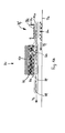
- device Bv comprises an applicator Fk, a clipboard Zv and a carrier tape Tb for a substrate Su, for example, a pizza dough.
- the application device Fk and the intermediate storage device Zv are arranged above the carrier tape Tb.
- Only Fig. 1 a shows, in addition to the further subfigures 1b, 1c, 1d, 1e, 1f, the application device Fk.
- the illustrated individual substrate Su is merely one example of a plurality of substrates lying one behind the other on the carrier tape Tb, but not shown. In a production line a plurality of substrates Su on the carrier tape Tb in a row and possibly in several rows of substrates Su each juxtaposed.
- the carrier tape Tb conveys the substrate Su from right to left in the illustrated conveying direction Pf.
- the speed v Su of the carrier tape Tb with the substrate Su may for example be 12 m / min.
- a pizza dough base for example, has a diameter of 30 cm.
- the device Bv according to the invention further comprises an application device, which is formed by a centrifugal separator Fk or another application device.
- the centrifugal separator Fk is supplied with a fluid-mass flow Fm from slip component Bk, for example cheese shavings, in an air flow.
- the cheese chips Bk are fed to the air flow in the mixing unit Me. Via a valve Vt, the fluid-mass flow can be regulated.
- the slip component Bk is separated from the fluid.
- the fluid can be recycled in a circuit to the mixing unit Me.
- the centrifugal separator Fk has an outlet section Aa, which allows the deposited slip component Bk to fall onto the intermediate storage surface in the form of a storage belt Ab.
- the centrifugal separator Fk can be pivoted in three spatial directions.
- the centrifugal separator Fk is gimballed (not shown).
- the device Bv comprises the intermediate storage area in the form of the strip Ab, which can be flexibly wound around a deflection edge Kr with a small radius.
- This storage belt Ab can consist of a single-layer polyurethane (PU) belt.
- PU polyurethane
- the Ablageband Ab extends as possible over the entire width of the carrier tape Tb, but at least over the occupied by the substrate Su transport width.
- the Ablageband Ab is attached with its two ends En to a holder Ht.
- the holder Ht is used only for attachment and retention of the storage belt Ab and is, apart from the storage belt Ab, compared to the other elements shown in Fig.
- the storage belt Ab is held stationary at its ends.
- the storage belt Ab would not necessarily have to have two ends, but could be designed as an endless belt. In this case, it would be held in place by the holder Ht.
- the holder Ht does not move.
- the holder Ht can be for example a U-profile or rectangular profile.
- the centrifugal Fk On the storage belt Ab is located on the right side of the holder Ht a deposition surface Df for the document component BK, which have been deposited by means of the centrifugal separator Fk on this deposition surface Df on the storage belt Ab.
- the centrifugal Fk can be pivoted in several degrees of freedom.
- the centrifugal Fk can be gimballed.
- a format device Fv for the targeted distribution of the document component Bk is also arranged directly above the Ablageband Ab, which is in the form of a substantially elliptical, upstanding metal edge.
- the Ablageband Ab is wrapped around a horizontally held support plate Sp.
- the support plate Sp may be, for example, an aluminum plate or a stainless steel plate.
- the selection of this material is largely determined by criteria that arise from the field of application, such as food technology, as well as the criterion of a low mass, so that only a small force has to be expended for their acceleration.
- the flexible Ab Ablageband is looped on the right side over a discharge edge Kr and thus extends from the top of the support plate Sp to the bottom.
- the Ablageband Ab is also wrapped on the left side over another edge KI of the support plate Sp and thus extends from the bottom of the support plate Sp up to the top.
- the support plate Sp is held via a support arm Sa in the holder Ht.
- the support plate Sp is horizontally displaceable, so that it is not held stationary.
- the support arm Sa can be held in the holder Ht via a piston Ko.
- the piston Ko is horizontally displaceable by a (not shown) piston drive in the holder Ht.
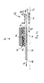
- This displacement is in the sequence of 1a ⁇ 1b ⁇ 1c ⁇ 1d ⁇ 1e ⁇ 1f demonstrates: While the support arm Sa in the case of Fig. 1 a is still completely on the right side of the holder Ht, he is in the sequence Fig. 1b ⁇ 1c ⁇ 1d ⁇ 1e ⁇ 1f are increasingly shifted to a more left position with respect to the holder Ht, wherein he in Fig. 1f has reached the leftmost position.
- the support plate Sp can of course be held displaceable in other ways in the clipboard Zv, for example by means of a pneumatic actuator, which may also be fixedly arranged elsewhere in the device.
- Fig. 1a ⁇ 1b ⁇ 1c ⁇ 1d ⁇ 1e ⁇ 1f illustrates the process of transferring the document component Bk from the clipboard Ab to the substrate Su:
- Fig. 1a it is shown that the document component Bk is deposited by means of the applicator on the deposition surface Df on the Ablageband Ab, bounded by the upstanding metal edge Fv.
- a substrate Su has been conveyed by the carrier tape Tb to a position below the deposition surface Df.
- the linear velocity of the carrier tape Tb is 12 m / min, for example, and the diameter of the substrate Su is about 30 cm.
- a first axis and a second axis of an elliptically shaped metal edge Fv are also about 30 cm.
- the linear feed of the support plate Sp is activated, for example, via a light barrier, so that the plate is moved in the indicated arrow direction Ps to the left, via the position in FIG Fig. 1b , the position in Fig. 1c , the position in Fig. 1 d , the position in Fig. 1 e up to the position in Fig. 1 f.
- the vast majority of the Ablagebandes Ab is moved in the direction of arrow Ps to the left.
- This feed process can take, for example, about 250 ms.
- the document component Bk lies completely still on the deposition surface Df. Only at the moment when the discharge edge Kr and thus the line Kr formed by this edge reaches the right edge of the deposition surface Df (see FIG Fig. 1c ), the document component Bk starts to fall on the substrate Su. In the position of Fig. 1d already part of the document component Bk has dropped from the deposition surface Df to the substrate Su, in the position of Fig. 1e an even greater part, and in the position of Fig. 1f the entire amount of the document component Bk has been transferred from the deposition surface Df to the substrate Su.
- the entire process of moving the support plate Sp lasts, for example, about 250 ms, so that the carrier tape Tb moves only slightly to the left during this period:
- the support plate Sp is moved back so that they in the starting position of Fig. 1a arrives. This process can take about 250 ms.
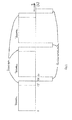
- the document component Bk After loading the deposition surface Df ("loading") (1.5 s) with the document component Bk, the document component Bk is transferred to the substrate Su within 250 ms ("transfer”) (1.75 s). Thereafter, the support plate Sp is transferred back to the starting position within a further 250 ms ("shift back”) (2.0 s).
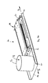
- the clipboard device Zv comprises a holder Ht for a depositing belt Ab and a supporting plate Sp, which is looped around by the depositing belt Ab.
- the Ablageband Ab is wrapped on the discharge edge Kr and on the other edge KI of the support plate Sp around and secured over the ends En of the band Ab at laterally downstanding legs Sc of the holder Ht by clamping.
- the discharge edge Kr and the further edge KI are formed by round rods welded to the support plate Sp at the front side and having a diameter of 3 mm. By the round bars Ablageband Ab can be easily pulled over these edges Kr, KI.
- the holder Ht with the legs Sc and the attachment points for the ends of En Ablagebandes Ab are held stationary (not shown).
- the support plate Sp is slidably held and driven in the directions Ps.
- the drive used for this purpose is not shown.
- a support arm Sa which is fixedly connected to the support plate Sp, and a guide rail Fs, on which the support arm Sa runs.
- the storage belt Ab is taken along, so that it is pulled over the discharge edge Kr. This reduces or increases the shelf space left of the holder Ht.
- a format device Fv is held in the form of an upright metal edge.
Landscapes
- Life Sciences & Earth Sciences (AREA)
- Engineering & Computer Science (AREA)
- Food Science & Technology (AREA)
- Specific Conveyance Elements (AREA)
Applications Claiming Priority (1)
| Application Number | Priority Date | Filing Date | Title |
|---|---|---|---|
| DE201110007193 DE102011007193B4 (de) | 2011-04-12 | 2011-04-12 | Vorrichtung und Verfahren zum Belegen zumindest eines Abschnittes eines Substrats mit mindestens einer Belegkomponente sowie Verwendung der Vorrichtung |
Publications (1)
| Publication Number | Publication Date |
|---|---|
| EP2510792A2 true EP2510792A2 (fr) | 2012-10-17 |
Family
ID=46027623
Family Applications (1)
| Application Number | Title | Priority Date | Filing Date |
|---|---|---|---|
| EP20120163708 Withdrawn EP2510792A2 (fr) | 2011-04-12 | 2012-04-11 | Dispositif et procédé de revêtement d'au moins une section d'un substrat avec au moins un composant de revêtement ainsi que l'utilisation du dispositif |
Country Status (2)
| Country | Link |
|---|---|
| EP (1) | EP2510792A2 (fr) |
| DE (1) | DE102011007193B4 (fr) |
Cited By (1)
| Publication number | Priority date | Publication date | Assignee | Title |
|---|---|---|---|---|
| CN109195446A (zh) * | 2016-04-04 | 2019-01-11 | 创造者公司 | 将调味料和酱汁分配到食品上的系统和方法 |
Families Citing this family (1)
| Publication number | Priority date | Publication date | Assignee | Title |
|---|---|---|---|---|
| CN112425618B (zh) * | 2020-11-30 | 2022-01-04 | 东台市汉源食品机械制造有限公司 | 一种面包表层均匀撒料装置 |
Citations (5)
| Publication number | Priority date | Publication date | Assignee | Title |
|---|---|---|---|---|
| US4264634A (en) | 1977-10-26 | 1981-04-28 | J. E. Grote Pepp-A-Matic Co., Inc. | Method for applying grated cheese to pizza shells |
| AT375813B (de) | 1982-12-21 | 1984-09-10 | Prohaska Franz Gmbh | Berieselungseinrichtung |
| EP1875805A1 (fr) | 2006-07-06 | 2008-01-09 | Multipond Wägetechnik GmbH | Dispositif de distribution et procédé destiné à la répartition automatique d'ingrédients sur un fond de pâte |
| DE102007005735A1 (de) | 2007-01-31 | 2008-08-14 | Dr. August Oetker Nahrungsmittel Kg | Verfahren und Vorrichtung zum Dekorieren oder Belegen eines Horizontalabschnitts einer flachen Backware |
| EP2294920A2 (fr) | 2009-09-09 | 2011-03-16 | SKS Sondermaschinen- und Fördertechnikvertriebs- GmbH | Dispositif et procédé de garnissage d'au moins une section d'un aliment |
Family Cites Families (2)
| Publication number | Priority date | Publication date | Assignee | Title |
|---|---|---|---|---|
| DE19740737C2 (de) * | 1997-09-16 | 1999-09-09 | Meggle Gmbh | Verfahren zur Herstellung von flachen Formstücken aus Butter oder Lebensmittelmassen ähnlicher Konsistenz und flache Formstücke aus Lebensmittelmasse |
| DE10000773A1 (de) * | 2000-01-11 | 2001-07-19 | Meggle Gmbh | Verfahren zur Speisezubereitung und tiefgefrorene Speiseergänzungsplatte als Zwischenprodukt im Rahmen dieses Verfahrens |
-
2011
- 2011-04-12 DE DE201110007193 patent/DE102011007193B4/de not_active Expired - Fee Related
-
2012
- 2012-04-11 EP EP20120163708 patent/EP2510792A2/fr not_active Withdrawn
Patent Citations (5)
| Publication number | Priority date | Publication date | Assignee | Title |
|---|---|---|---|---|
| US4264634A (en) | 1977-10-26 | 1981-04-28 | J. E. Grote Pepp-A-Matic Co., Inc. | Method for applying grated cheese to pizza shells |
| AT375813B (de) | 1982-12-21 | 1984-09-10 | Prohaska Franz Gmbh | Berieselungseinrichtung |
| EP1875805A1 (fr) | 2006-07-06 | 2008-01-09 | Multipond Wägetechnik GmbH | Dispositif de distribution et procédé destiné à la répartition automatique d'ingrédients sur un fond de pâte |
| DE102007005735A1 (de) | 2007-01-31 | 2008-08-14 | Dr. August Oetker Nahrungsmittel Kg | Verfahren und Vorrichtung zum Dekorieren oder Belegen eines Horizontalabschnitts einer flachen Backware |
| EP2294920A2 (fr) | 2009-09-09 | 2011-03-16 | SKS Sondermaschinen- und Fördertechnikvertriebs- GmbH | Dispositif et procédé de garnissage d'au moins une section d'un aliment |
Cited By (2)
| Publication number | Priority date | Publication date | Assignee | Title |
|---|---|---|---|---|
| CN109195446A (zh) * | 2016-04-04 | 2019-01-11 | 创造者公司 | 将调味料和酱汁分配到食品上的系统和方法 |
| CN109195446B (zh) * | 2016-04-04 | 2021-06-11 | 创造者公司 | 将调味料和酱汁分配到食品上的系统和方法 |
Also Published As
| Publication number | Publication date |
|---|---|
| DE102011007193B4 (de) | 2013-11-07 |
| DE102011007193A1 (de) | 2012-10-18 |
Similar Documents
| Publication | Publication Date | Title |
|---|---|---|
| EP1952693B1 (fr) | Procédé et dispositif de décoration ou de garniture d'une section horizontale d'un produit de boulangerie plat | |
| EP3684714B1 (fr) | Dispositif de distribution permettant la distribution de produits sur une bande transporteuse | |
| EP2789239A1 (fr) | Dispositif et procédé de fabrication de produits moulés en forme de boule | |
| DE2211484A1 (de) | Verfahren und Vorrichtung zum Fördern von Gegenständen mit Schüttelförderern | |
| WO2018069551A1 (fr) | Machine de récolte de plantes sarclées | |
| DD208911A5 (de) | Vorrichtung zum beschichten einzelner auf einer transportvorrichtung aneinander anliegend transportierter waffelblaetter od. dgl. backprodukte mit streichmassen | |
| DE102016108003A1 (de) | Maschine sowie Verfahren zum Umsetzen von Produkten | |
| DE102011007193B4 (de) | Vorrichtung und Verfahren zum Belegen zumindest eines Abschnittes eines Substrats mit mindestens einer Belegkomponente sowie Verwendung der Vorrichtung | |
| DE2835404C2 (de) | Vorrichtung zum Bevorraten und Ausgeben von Gegenständen | |
| EP3068713B1 (fr) | Procédé et dispositif de transport et de regroupement de produits en morceaux | |
| DE3900414C2 (fr) | ||
| DE1900615A1 (de) | Vorrichtung zum Palettieren,insbesondere fuer Schlauchabschnittpakete | |
| EP1884161B1 (fr) | Procédé et dispositif destinés au garnissage ou remplissage de produits intermédiaires | |
| DE1932547B2 (de) | Foerderleitung fuer zigaretten oder aehnliche stueckige gegenstaende mit einem volumenvariablen vorratsraum | |
| DE2538334A1 (de) | Einrichtung zum verteilen von tabak | |
| EP4431251A1 (fr) | Ensemble de préhension à comportement de largage réglable | |
| DE102022111999A1 (de) | Vorrichtung | |
| DE20004896U1 (de) | Stückgut-Stetigfördereinrichtung | |
| EP0582089A1 (fr) | Dispositif et procédé pour emballer un produit avec précaution | |
| DE1907123C3 (de) | Vorrichtung zum Auflösen einer von mehreren parallelen Reihen von Behältern gebildeten Schicht | |
| DE3704665C2 (de) | Verfahren und Vorrichtung zur kontinuierlichen Herstellung von spiralförmigen Teigwaren | |
| DE102012200821A1 (de) | Vorrichtung und Verfahren zum Aufbringen mindestens einer Belegkomponente auf ein Substrat | |
| DE69501146T2 (de) | Vorrichtung zur Bildung von Produktstapeln, z.B. in Anlagen zum automatischen Verpacken von Nahrungsmitteln | |
| CH660312A5 (de) | Vorrichtung zum absondern fehlerhafter flacher dauerbackwaren. | |
| DE3130103A1 (de) | Verfahren und vorrichtung zur automatischen vorbereitung der verpackung von leicht zerbechlichen produkten, beispielsweise mohrenkoepfen |
Legal Events
| Date | Code | Title | Description |
|---|---|---|---|
| PUAI | Public reference made under article 153(3) epc to a published international application that has entered the european phase |
Free format text: ORIGINAL CODE: 0009012 |
|
| AK | Designated contracting states |
Kind code of ref document: A2 Designated state(s): AL AT BE BG CH CY CZ DE DK EE ES FI FR GB GR HR HU IE IS IT LI LT LU LV MC MK MT NL NO PL PT RO RS SE SI SK SM TR |
|
| AX | Request for extension of the european patent |
Extension state: BA ME |
|
| STAA | Information on the status of an ep patent application or granted ep patent |
Free format text: STATUS: THE APPLICATION IS DEEMED TO BE WITHDRAWN |
|
| 18D | Application deemed to be withdrawn |
Effective date: 20171103 |