EP2511034B1 - Griff und Aufsätze für Winkelbohrer - Google Patents
Griff und Aufsätze für Winkelbohrer Download PDFInfo
- Publication number
- EP2511034B1 EP2511034B1 EP12171664.1A EP12171664A EP2511034B1 EP 2511034 B1 EP2511034 B1 EP 2511034B1 EP 12171664 A EP12171664 A EP 12171664A EP 2511034 B1 EP2511034 B1 EP 2511034B1
- Authority
- EP
- European Patent Office
- Prior art keywords
- handle
- power tool
- housing
- mounting
- hand
- Prior art date
- Legal status (The legal status is an assumption and is not a legal conclusion. Google has not performed a legal analysis and makes no representation as to the accuracy of the status listed.)
- Not-in-force
Links
Images





Classifications
-
- B—PERFORMING OPERATIONS; TRANSPORTING
- B25—HAND TOOLS; PORTABLE POWER-DRIVEN TOOLS; MANIPULATORS
- B25F—COMBINATION OR MULTI-PURPOSE TOOLS NOT OTHERWISE PROVIDED FOR; DETAILS OR COMPONENTS OF PORTABLE POWER-DRIVEN TOOLS NOT PARTICULARLY RELATED TO THE OPERATIONS PERFORMED AND NOT OTHERWISE PROVIDED FOR
- B25F5/00—Details or components of portable power-driven tools not particularly related to the operations performed and not otherwise provided for
- B25F5/02—Construction of casings, bodies or handles
- B25F5/025—Construction of casings, bodies or handles with torque reaction bars for rotary tools
- B25F5/026—Construction of casings, bodies or handles with torque reaction bars for rotary tools in the form of an auxiliary handle
-
- B—PERFORMING OPERATIONS; TRANSPORTING
- B23—MACHINE TOOLS; METAL-WORKING NOT OTHERWISE PROVIDED FOR
- B23B—TURNING; BORING
- B23B45/00—Hand-held or like portable drilling machines, e.g. drill guns; Equipment therefor
- B23B45/001—Housing of the drill, e.g. handgrip
-
- B—PERFORMING OPERATIONS; TRANSPORTING
- B25—HAND TOOLS; PORTABLE POWER-DRIVEN TOOLS; MANIPULATORS
- B25F—COMBINATION OR MULTI-PURPOSE TOOLS NOT OTHERWISE PROVIDED FOR; DETAILS OR COMPONENTS OF PORTABLE POWER-DRIVEN TOOLS NOT PARTICULARLY RELATED TO THE OPERATIONS PERFORMED AND NOT OTHERWISE PROVIDED FOR
- B25F5/00—Details or components of portable power-driven tools not particularly related to the operations performed and not otherwise provided for
- B25F5/02—Construction of casings, bodies or handles
-
- Y—GENERAL TAGGING OF NEW TECHNOLOGICAL DEVELOPMENTS; GENERAL TAGGING OF CROSS-SECTIONAL TECHNOLOGIES SPANNING OVER SEVERAL SECTIONS OF THE IPC; TECHNICAL SUBJECTS COVERED BY FORMER USPC CROSS-REFERENCE ART COLLECTIONS [XRACs] AND DIGESTS
- Y10—TECHNICAL SUBJECTS COVERED BY FORMER USPC
- Y10T—TECHNICAL SUBJECTS COVERED BY FORMER US CLASSIFICATION
- Y10T408/00—Cutting by use of rotating axially moving tool
- Y10T408/65—Means to drive tool
-
- Y—GENERAL TAGGING OF NEW TECHNOLOGICAL DEVELOPMENTS; GENERAL TAGGING OF CROSS-SECTIONAL TECHNOLOGIES SPANNING OVER SEVERAL SECTIONS OF THE IPC; TECHNICAL SUBJECTS COVERED BY FORMER USPC CROSS-REFERENCE ART COLLECTIONS [XRACs] AND DIGESTS
- Y10—TECHNICAL SUBJECTS COVERED BY FORMER USPC
- Y10T—TECHNICAL SUBJECTS COVERED BY FORMER US CLASSIFICATION
- Y10T408/00—Cutting by use of rotating axially moving tool
- Y10T408/96—Miscellaneous
Definitions
- the present disclosure relates to handles and, more particularly, to handles and attachments that can be used on a power tool, such as a right angle drill.
- Hand held power tools such as drills and drivers, may include a housing and a handle attached thereto.
- the handle is a single stick-type handle that has a butt face attachment to the housing. This attachment results in a small footprint or mounting area for the handle on the housing.
- the power tool can generate high torque.
- the small footprint or mounting area for the handle on the housing can limit the distribution of the loading due to the high torque.
- the power tool can be heavy and, being handheld, can be subject to being dropped. When dropped, the power tool may land on the handle or at an angle relative to the handle such that a large bending moment can occur at the location of the attachment of the handle to the housing.
- the small footprint or mounting area limits the ability of the handle to distribute the load and reduce the load concentration.
- the power tools can be subject to having the handle break when the power tool is subjected to large torque loading and/or dropped. Breaking the handle can make the power tool useless until a replacement handle is attached. Additionally, the need to purchase replacement handles increases the cost of ownership of the power tool. Thus, it would be advantageous if the handle loading could be spread out along a greater portion of the housing to reduce the stress concentrations during use and/or when the power tool is dropped to reduce the chance of the handle breaking. Additionally, the spreading of the stresses may also allow the use of different materials which may be more economical.
- the power tools may generate large amounts of torque.
- strong and violent forces may be incurred when the tool encounters an obstruction.
- the high torque produced by the power tool can cause it to rotate about the chuck axis.
- the operator may resist the rotation by holding onto the handle, or bracing it against a solid object.
- a large bending moment can occur at the location of the attachment of the handle to the housing due to the high torque.
- the auger bit can catch on a nail or similar feature, such as a knot.
- the handle may not afford protection for the hand of a user. Additionally, the user's hand could possibly become trapped against the trigger and the work piece, thereby preventing the release of the trigger and de-energization of the power tool. As a result, the user may need to wait until the motor burns up or the power tool may need to be unplugged to de-energize the motor and allow the user to remove their trapped hand.
- the handle included features that distributed the load due to the high torque and/or to protect the user's hand. Additionally, it would be advantageous if the handle facilitated the allowing of a user to release the trigger regardless of the tool being trapped against a work piece.
- the invention provides a power tool as defined in claim 1.
- the guard handle can advantageously provide protection for a user's hand when operating the power tool.
- the handle may advantageously be utilized to position sensors therein at positions that are remote from the working bit of the power tool.
- Example embodiments will now be described more fully with reference to the accompanying drawings. Example embodiments are provided so that this disclosure will be thorough, and will fully convey the scope to those who are skilled in the art. Numerous specific details are set forth such as examples of specific components, devices, and methods, to provide a thorough understanding of embodiments of the present disclosure. It will be apparent to those skilled in the art that specific details need not be employed, that example embodiments may be embodied in many different forms and that neither should be construed to limit the scope of the disclosure. In some example embodiments, well-known processes, well-known device structures, and well-known technologies are not described in detail.
- power tool 20 such as a powered drill or driver by way of non-limiting example.
- power tool 20 is a right-angle drill.
- Power tool 20 includes a housing 24 to which a handle is attached.
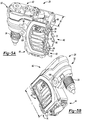
- power tool 20 has a guard handle 26 attached to housing 24 while in the embodiments shown in Figures 2 and 4 , power tool 20 has a stick handle 28 attached to housing 24.
- Handles 26, 28 include a trigger assembly 30 that can activate power tool 20.
- Housing 24 can contain, for example, a motor 32 that can drive a transmission 33 that ultimately provides a torque output to a drive spindle 36.
- Transmission 33 can include a plurality of gears or gear sets to achieve the desired torque and speed output of drive spindle 36 in response to operation of motor 32.
- a chuck assembly 34 can be attached to an end of drive spindle 36.
- Trigger assembly 30 can be retracted to energize motor 32 to drive transmission 33 and drive spindle 36.
- Chuck assembly 34 can be opened and closed to accept the various tools or bits.
- Housing 24 includes a mounting surface 40 that can be generally rectangular in shape and extends between upper and lower surfaces 42, 44 and between left and right side surfaces 46, 48.
- Motor 32 is contained within a rear portion 50 of housing 24 while drive spindle 36 is contained in a front portion 52.
- Mounting surface 40 is adjacent to rear portion 50.
- Chuck assembly 34 extends from lower surface 44 of front portion 52.
- Transmission 33 is disposed in housing 24 and can extend in both rear portion 50 and front portion 52.
- a lever 56 can be disposed on left side surface 46 of housing 24.
- Lever 56 can be coupled to a shifting mechanism that changes the operation of transmission 33 and power tool 20 between first and second operating conditions. The first and second operating conditions can be related to a torque output and/or rotational speed of drive spindle 36.
- Handles 26, 28 can each be a two-piece construction.
- the left side halves of handles 26, 28 are shown.
- the left sides of handles 26, 28 mount with the right halves, which can be mirror images of the left halves, of the handle to form the complete handle assembly which can be coupled to housing 24, as described below.
- Handles 26, 28 each include a gripping portion 60 that facilitates gripping of power tool 20 by a user.
- Trigger assembly 30 is disposed adjacent gripping portion 60 to allow a user to energize power tool 20.
- Both handles 26, 28 include a mounting portion 62 that is configured to be attached to mounting surface 40 of housing 24, as described below.
- gripping portion 60 extends from an upper section of mounting portion 62 adjacent to upper surface 42 of housing 24 and also includes a guard portion 64 that extends from an end of gripping portion 60 to a lower section of mounting portion 62 adjacent lower surface 44 of housing 24.
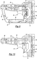
- Guard portion 64 and gripping portion 60 form a protected opening 66 through which the hand of a user extends when operating power tool 20, as shown in Figure 12 .
- Guard portion 64 can be generally L-shaped and can include first and second sections 65, 67. Guard portion 64 can serve to provide additional protection for the hand of a user operating power tool 20. Specifically, when operating power tool 20, if the working bit were to grip the object being worked on and pull power tool 20 thereto, guard portion 64 may protect the user's hands from being crushed or injured during such an operation. Guard portion 64 may also allow the user to release trigger assembly 30 in such an event. Guard portion 64 can provide additional benefits, as described below.
- Mounting portion 62 is configured to extend along the entire length L of mounting surface 40 between upper and lower surfaces 42, 44 and along the entire width W of mounting surface 40 between left and right side surfaces 46, 48. As a result, mounting portion 62 could be engaged with up to an entirety of the periphery of mounting surface 40.
- This large maximized interface area allows for forces imparted onto the handle (i.e., as a result of torque loading during use, such as when using the handle as a brace, and/or as a result of dropping) to be distributed over a large area. As a result, stress concentrations can be reduced and a propensity or likelihood of breaking power tool 20 can also be reduced.
- guard portion 64 in conjunction with gripping portion 60 facilitates the transferring of forces throughout mounting portion 62 in the event that power tool 20 having guard handle 26 is subjected to high forces on the handle.
- the force will be transferred to both the end of gripping portion 60 via section 65 and the lower section of mounting portion 62 via second section 67.
- the force will be transferred to guard portion 64 and to the upper section of mounting portion 62.
- This transmitting of forces disperses the loading such that stresses are reduced in magnitude.
- mounting portion 62 extending along and up to an entire periphery of mounting surface 40 on housing 24, the stresses are further distributed throughout mounting portion 62 and housing 24. As a result, the propensity or chance of catastrophic failure or breaking of guard handle 26 is reduced.
- Guard handle 26 also facilitates the carrying of power tool 20.
- a user can easily carry power tool 20 by gripping first section 65 of guard portion 64.
- This configuration allows the heaviest part of power tool 20, housing 24, to be lower than guard handle 26.
- First section 65 can also be located directly above the center of gravity of power tool 20, thereby reducing the stress on the user when carrying power tool 20, since there will not be a moment arm.
- a user can easily transport power tool 20 by gripping guard handle 26.
- gripping portion 60 can extend from a central section of mounting portion 62.
- the centralized extension of gripping portion 60 facilitates the transferring of forces to mounting portion 62.
- the centralized gripping portion 60 can distribute the resulting stress across mounting portion 62.
- mounting portion 62 extending along up to the entire periphery of mounting surface 40 of housing 24, the resulting stress is distributed over a large area. As a result, the stress in any particular location can be reduced. The reduction in the stress can reduce the frequency of breakage that may occur when power tool 20 having stick handle 28 is exposed to high forces on the handle.
- guard handle 26 to housing 24 is illustrated. It should be appreciated that mounting portions 62 of handles 26, 28 are the same such that the features of mounting portion 62 shown in these figures are also included in the mounting portion 62 of stick handle 28. Additionally, the benefits associated with the mounting techniques may be realized by both handles 26,28.
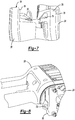
- mounting portion 62 of each half of handle 26 includes a plurality of ribs 70 that extend from mounting portion 62 toward the other half.
- Housing 24 includes a pair of flanges 72 that extend along mounting surface 40 substantially the entire length between upper and lower surfaces 42, 44 adjacent to left and right side surfaces 46, 48.
- Flanges 72 include a plurality of recesses 74 that are spaced along flanges 72. Recesses 74 are configured to receive ribs 70 of mounting portion 62.
- Flanges 72 can include three recesses 74 and each half of handle 26 can include three ribs 70. The engagement of ribs 70 with recesses 74 interlocks mounting portion 62 with housing 24.
- mounting surface 40 includes an engagement shoulder 76 adjacent to flanges 72 that engages with front end surface 78 of the handle. Shoulders 76 also extend between flanges 72 adjacent upper and lower surfaces 42, 44. The engagement of surface 78 with shoulder 76 in conjunction with engagement of ribs 70 with recesses 74 facilitates the distributing of loads along mounting portions 62 and mounting surface 40. This distribution can reduce stress that can occur as a result of high forces on the handle. The reduced stress can also reduce the propensity of the handle breaking when power tool 20 is exposed to high forces on the handle.
- Mounting portion 62 can also include a pair of cylindrical-shaped bosses 82 that extend from one handle half toward the other handle half. Bosses 82 are received within openings 84 in flanges 72. The bosses 82 on one half of the handle align with the bosses 82 on the other half of the handle and include an opening 86 therein. Openings 86 can receive a fastener so that the two handle halves can be secured together with the fastener extending through and engaging with the bosses 82 on the two handle halves. The engagement of bosses 82 with openings 84 and flanges 72 further interlocks mounting portion 62 to mounting surface 40 of housing 24.
- the engagement of ribs 70 with recesses 74 along with the engagement of bosses 82 with openings interlocks mounting portions 62 to housing 24 and inhibits removal of the handle from housing 24.
- This interlocking also facilitates the proper alignment of the handle on housing 24 during assembly.
- This configuration can also facilitate increased durability in that the fasteners used to secure the two handle halves together are loaded in shear when the handle is subjected to torque forces. As a result, the fasteners can rely upon their shear strength as opposed to relying upon the tensile strength of the fastener threads and/or the threads of the bosses that are used to secure the fasteners.
- the threads of the fastener and/or of the bosses 82 can be a weak point, thereby allowing failure of the handle.
- the shear loading may enable the handle to sustain higher forces without breaking.
- handles 26, 28 that are formed from two halves can facilitate the assembly of power tool 20.
- one of the halves of handle 26, 28 can be engaged with one of flanges 72 on housing 24, as shown. With this engagement, the routing of the power cord 90 and trigger assembly 30 through handle 26, 28 can be performed.
- the wiring and arrangement of the various components and assemblies can be easily secured in the proper orientation and, furthermore, secured to motor 32 and other features within housing 24. With these electrical connections made and the components secured in their proper position, the other half of handle 26, 28 can then be positioned to engage with the recesses 74 and openings 84 in flange 72 and aligned with the existing half of handle 26, 28.
- Fasteners can then be utilized to secure the two halves of handles 26, 28 together through engagement with various bosses 94 extending from the internal portions of the handle halves.
- guard handle 26 can also provide the additional benefit of providing additional room for disposing electronics for power tool 20 in the handle.
- an electronic module 98 can be disposed in second section 67 of guard portion 64, as shown in Figure 9 .
- Module 98 may include one or more sensors. It may be desirable to locate sensors of module 98 in a position that is away from the power cord 90, trigger assembly 30, and motor 32 to reduce possible electro-magnetic interference or noise. As a result, module 98 may advantageously be disposed in second section 67 of guard portion 64, as shown in Figure 9 .
- guard portion 64 can advantageously allow additional storage location for controller sensors and the like and may also allow the positioning of such controllers, sensors, and the like in a position that is away from power cord 90, trigger assembly 30, and motor 32.
- power tool 20 can include one or more optional handles.
- power tool 20 can include a bail handle 102 and/or a side handle 104.
- Bail handle 102 and side handle 104 can be attached to housing 24 through a single attachment feature disposed on left and right side surfaces 46, 48.
- the attachment feature 106 can be a threaded bore 106 that is machined into left and right side surfaces 46, 48 of housing 24 during manufacture of same.
- Bail handle 102 can be generally U-shaped and include first and second arms 108, 110 with a connecting section 112 extending therebetween.
- first and second arms 108, 110 can each include a collar 114, 116 that can each have an opening 118, 120 therethrough that aligns with bores 106 on respective left and right side surfaces 46, 48 of housing 24 with connecting section 112 extending across upper surface 42.
- Arms 108, 110 can be curved such that connecting section 112 extends across upper surface 42 in proximity to the rotational axis of drive spindle 36 and chuck assembly 34.
- Bail handle 102 can be attached to housing 24 with a pair of adapters 126.
- bail handle 102 can be secured to power tool 20 in a variety of different orientations.
- bail handle 102 can be attached to power tool 20 in the orientation shown in Figure 13 .
- Bail handle 102 can also be rotated relative to power tool 20 and secured thereto in a different orientation so long as collars 114, 116 are aligned with openings 118, 120.
- the ability to position bail handle 102 in different orientations can aid the user in finding a gripping position that is suitable for the use to which power tool 20 is to be employed.
- Adapters 126 include a threaded portion 128, a cylindrical portion 130, and a head portion 132. Adapters 126 also include a shoulder 134 at the interface of threaded portion 128 to cylindrical portion 130 and a shoulder 136 at the interface of cylindrical portion 130 and head portion 132. Head portion 132 can include a plurality of flats 140 that can facilitate rotation of adapter 126 by a wrench or the like. Threaded portion 128 is complementary to threaded bore 106 and can be received therein by relative rotation. Openings 118, 120 in collars 114, 116 are complementary to cylindrical portion 130 such that cylindrical portion 130 can be disposed within openings 118, 120.
- Adapters 126 are configured to also allow side handle 104 to be attached thereto.
- adapters 126 can include a threaded bore 138 that extends through head portion 132 and cylindrical portion 130.
- Side handle 104 can include a threaded portion 144 that is complementary to threaded bore 138.
- Side handle 104 can be attached to power tool 20 by engaging threaded portion 144 with threaded bore 138 and rotating side handle 104 relative to adapter 126.
- Side handle 104 can be attached to either the left or right sides of power tool 20 by engaging with adapter 126 attached thereto.
- adapter 126 allows both bail handle 102 and one or more side handles 104 to be attached to power tool 20 utilizing a single threaded bore 106 on the left and right side surfaces 46, 48 of housing 24. If desired, a pair of side handles 104 can be attached to both sides of power tool 20 in conjunction with bail handle 102.
- Threaded bore 138 can have the same relative dimensions of bore 106 of housing 24. Additionally, threaded portion 144 of side handle 104 can have the same relative dimensions of threaded portion 128 of adapters 126. When this is the case, side handle 104 can be attached directly to housing 24 without the use of adapter 126. Specifically, threaded portion 144 can be engaged with threaded bore 106 and side handle 104 rotated relative to housing 24 to attach side handle 104 to housing 24. In this case, bail handle 102 is not utilized.
- power tool 20 can utilize both a bail handle 102 and side handle 104 simultaneously and can allow the attachment thereto through the use of a single threaded bore 106 on the left and right side surfaces 46, 48 of housing 24.
- bail handle 102 can be used without side handle 104 with adapters 126 securing bail handle 102 to housing 24.
- one or more side handles 104 can be used without bail handle 102 by directly engaging threaded portion 144 of side handle 104 with threaded bore 106 in housing 24.
- the use of adapters 126 can allow for a plurality of arrangements for an optional bail handle 102 and side handle 104 for use on a power tool 20.
- a single threaded bore 106 on each of the left and right side surfaces 46, 48 of housing 24 can be utilized, thereby reducing the requirement for two separate threaded bores on each side of the housing.
- the use of a single threaded bore 106 on each of the left and right side surfaces 46, 48 of housing 24 can advantageously allow for a more compact housing 24.
- the use of a single threaded bore 106 on each side allows for additional space for the internal components of housing 24 than may be available if two or more threaded bores are required on each side.
- the use of a single threaded bore 106 on the left and right side surfaces 46, 48 of housing 24 can allow for the locating of threaded bore 106 to be at a position that maximizes the benefit of using bail handle 102 and/or side handle 104. That is, the location can be selected so that controlling of power tool 20 is facilitated along with resisting the torque generated thereby. This capability may allow easier or more precise control of power tool 20 and may also prevent or reduce the chance of out-of-control operation.
Landscapes
- Engineering & Computer Science (AREA)
- Mechanical Engineering (AREA)
- Portable Power Tools In General (AREA)
- Drilling And Boring (AREA)
Claims (9)
- Elektrohandwerkzeug (20), umfassend:ein Gehäuse (24);einen Motor (32) in dem Gehäuse (34), undeine Antriebsspindel (36), die mit dem Motor (32) gekoppelt ist und um eine Achse dreht; undeinen Schutzgriff (26), der einen Montageabschnitt (62) hat, der an dem Gehäuse (24) befestigt ist, wobei der Griff (26) einen Greifabschnitt (60) hat, der sich von dem Montageabschnitt (62) mit einer Drückeranordnung (30) erstreckt, die den Motor (32) aktiviert, und einen Schutzabschnitt (64), der sich von einem Ende des Greifabschnitts (60) zu dem Montageabschnitt (62) erstreckt, wobei der Schutzabschnitt (64) im Allgemeinen L-förmig ist und einen ersten Abschnitt (65) und einen zweiten Abschnitt (67) umfasst, wobei sich der erste Abschnitt (65) von einem Ende des Greifabschnitts (60) erstreckt, wobei sich der zweite Abschnitt (67) von dem Montageabschnitt (62) erstreckt;ein Steuermodul (98), das in dem Schutzabschnitt (64) angeordnet ist und mindestens einen Sensor hat, der einen Betriebszustand des Elektrohandwerkzeugs (20) erfasst,dadurch gekennzeichnet, dass der mindestens eine Sensor in dem zweiten Abschnitt (67) des Schutzabschnitt (64) angeordnet ist.
- Elektrohandwerkzeug (20) nach Anspruch 1, wobei sich der zweite Abschnitt (64) des Schutzabschnitts (64) senkrecht zu der Drehachse der Antriebsspindel (36) erstreckt.
- Elektrohandwerkzeug (20) nach Anspruch 2, wobei der zweite Abschnitt (67) des Schutzabschnitts (64) im Wesentlichen zu dem Greifabschnitt (60) parallel ist.
- Elektrohandwerkzeug (20) nach einem der Ansprüche 1 bis 3, wobei:das Gehäuse (24) eine Montagefläche (40) mit einer Länge (L) und einer Breite (W) hat; undder Montageabschnitt (62) den Griff (26) an der Montagefläche (40) des Gehäuses (24) befestigt, wobei sich der Montageabschnitt (62) entlang einer gesamten Länge (L) und Breite (W) der Montageoberfläche (40) erstreckt.
- Elektrohandwerkzeug (20) nach Anspruch 4, wobei die Montagefläche (40) eine vollständige Seite des Gehäuses (24) definiert, und der Montageabschnitt (62) in mindestens die gesamte Peripherie der Montagefläche (40) eingreift.
- Elektrowerkzeug (20) nach einem der Ansprüche 4 oder 5, wobei die Montagefläche (40) ein Paar Flansche (72) aufweist, die sich entlang von zwei entgegengesetzten Seiten der Montagefläche (40) erstrecken und der Montageabschnitt (62) in die Flansche (72) blockierend eingreift.
- Elektrohandwerkzeug (20) nach Anspruch 6, wobei jeder der Flansche (72) eine Vielzahl von Aussparungen (74) aufweist, und der Montageabschnitt (62) eine Vielzahl von Rippen (70) aufweist, die in die Aussparungen (74) eingefügt sind, so dass der Griff (26) an dem Gehäuse (24) blockierend eingreift.
- Elektrohandwerkzeug (20) nach einem der Ansprüche 6 oder 7, wobei jeder der Flansche (72) eine Vielzahl durchgehender Öffnungen (84) aufweist, und der Montageabschnitt (62) eine Vielzahl von Höckern (82) aufweist, die sich durch die Öffnungen (84) erstrecken, wobei der Griff (26) an dem Gehäuse (24) blockierend eingreift.
- Elektrohandwerkzeug (20) nach einem der Ansprüche 4 bis 8, wobei der Montageabschnitt (62) mit dem Gehäuse (24) entlang im Wesentlichen einer gesamten Länge der Montagefläche (40) blockierend eingreift.
Applications Claiming Priority (3)
| Application Number | Priority Date | Filing Date | Title |
|---|---|---|---|
| US19777608P | 2008-10-30 | 2008-10-30 | |
| US12/604,739 US8690497B2 (en) | 2008-10-30 | 2009-10-23 | Handle and attachments for right angle drill |
| EP09174654.5A EP2181786B1 (de) | 2008-10-30 | 2009-10-30 | Handgeführtes elektrowerkzeug |
Related Parent Applications (3)
| Application Number | Title | Priority Date | Filing Date |
|---|---|---|---|
| EP09174654.5A Division EP2181786B1 (de) | 2008-10-30 | 2009-10-30 | Handgeführtes elektrowerkzeug |
| EP09174654.5A Division-Into EP2181786B1 (de) | 2008-10-30 | 2009-10-30 | Handgeführtes elektrowerkzeug |
| EP09174654.5 Division | 2009-10-30 |
Publications (3)
| Publication Number | Publication Date |
|---|---|
| EP2511034A2 EP2511034A2 (de) | 2012-10-17 |
| EP2511034A3 EP2511034A3 (de) | 2013-03-20 |
| EP2511034B1 true EP2511034B1 (de) | 2017-07-05 |
Family
ID=41343370
Family Applications (3)
| Application Number | Title | Priority Date | Filing Date |
|---|---|---|---|
| EP12171664.1A Not-in-force EP2511034B1 (de) | 2008-10-30 | 2009-10-30 | Griff und Aufsätze für Winkelbohrer |
| EP09174654.5A Not-in-force EP2181786B1 (de) | 2008-10-30 | 2009-10-30 | Handgeführtes elektrowerkzeug |
| EP12171661.7A Not-in-force EP2511033B1 (de) | 2008-10-30 | 2009-10-30 | Griff und Aufsätze für Winkelbohrer |
Family Applications After (2)
| Application Number | Title | Priority Date | Filing Date |
|---|---|---|---|
| EP09174654.5A Not-in-force EP2181786B1 (de) | 2008-10-30 | 2009-10-30 | Handgeführtes elektrowerkzeug |
| EP12171661.7A Not-in-force EP2511033B1 (de) | 2008-10-30 | 2009-10-30 | Griff und Aufsätze für Winkelbohrer |
Country Status (3)
| Country | Link |
|---|---|
| US (1) | US8690497B2 (de) |
| EP (3) | EP2511034B1 (de) |
| CN (1) | CN201552562U (de) |
Families Citing this family (20)
| Publication number | Priority date | Publication date | Assignee | Title |
|---|---|---|---|---|
| US8925646B2 (en) | 2011-02-23 | 2015-01-06 | Ingersoll-Rand Company | Right angle impact tool |
| US9592600B2 (en) | 2011-02-23 | 2017-03-14 | Ingersoll-Rand Company | Angle impact tools |
| US8820433B2 (en) | 2011-08-30 | 2014-09-02 | Black & Decker Inc. | Axially compact power tool |
| EP2636378A1 (de) * | 2011-09-07 | 2013-09-11 | Stryker Leibinger GmbH & Co. KG | Chirurgisches Elektrowerkzeug |
| US20140251650A1 (en) * | 2013-03-11 | 2014-09-11 | Makita Corporation | Power tool and power tool accessory member |
| US9022888B2 (en) | 2013-03-12 | 2015-05-05 | Ingersoll-Rand Company | Angle impact tool |
| CA2882992C (en) * | 2014-02-24 | 2022-07-12 | Kristopher J. Hurst | Magnetic mount for power tool |
| WO2019027954A1 (en) | 2017-07-31 | 2019-02-07 | Milwaukee Electric Tool Corporation | ROTARY ELECTRIC TOOL |
| CN108080723A (zh) * | 2017-12-22 | 2018-05-29 | 宁波星瑞克中空铝条有限公司 | 一种中空玻璃中铝条的锯切装置 |
| EP3560660A1 (de) * | 2018-04-25 | 2019-10-30 | HILTI Aktiengesellschaft | Anordnung für eine handwekzeugmaschine und handwerkzeugmaschine |
| ES2737100B2 (es) * | 2018-07-03 | 2020-07-23 | Univ Extremadura | Procedimiento para desencajar elementos encajables entre si y dispositivo para dicho procedimiento |
| CN111989076B (zh) * | 2018-12-26 | 2022-03-15 | 泰乐甘股份有限公司 | 冲击式按摩装置及使用方法 |
| US11890253B2 (en) | 2018-12-26 | 2024-02-06 | Therabody, Inc. | Percussive therapy device with interchangeable modules |
| USD926562S1 (en) * | 2019-03-14 | 2021-08-03 | Joseph E. Boyanich | Securing apparatus for hand grinder tool |
| USD946393S1 (en) * | 2019-03-14 | 2022-03-22 | Joseph E. Boyanich | Securing apparatus for hand grinder tool |
| USD947634S1 (en) * | 2020-12-04 | 2022-04-05 | Black & Decker Inc. | Angle drill |
| JP7716282B2 (ja) * | 2021-09-10 | 2025-07-31 | 株式会社マキタ | アタッチメント、及び電動掘削機 |
| US11759938B2 (en) | 2021-10-19 | 2023-09-19 | Makita Corporation | Impact tool |
| WO2025059992A1 (en) | 2023-09-21 | 2025-03-27 | Therabody, Inc. | Systems, methods, and devices for percussive massage therapy |
| US20250135599A1 (en) * | 2023-10-25 | 2025-05-01 | Harbor Freight Tools Usa, Inc. | Ergonomic adjustable grip for a hand-held power tool |
Family Cites Families (24)
| Publication number | Priority date | Publication date | Assignee | Title |
|---|---|---|---|---|
| US3077547A (en) | 1959-02-13 | 1963-02-12 | Sunbeam Corp | Portable electric drill |
| US3244030A (en) * | 1965-03-19 | 1966-04-05 | Stanley Works | Portable power tool |
| DE1628045B2 (de) * | 1967-01-13 | 1974-01-10 | Robert Bosch Gmbh, 7000 Stuttgart | Hammergerät mit einem quer zur Schlagrichtung eingebauten Antriebsmotor |
| US3990523A (en) | 1975-03-17 | 1976-11-09 | Schramm Buford J | Piston engine powered rotary drive with mount and fuel container |
| US4540318A (en) * | 1982-07-29 | 1985-09-10 | Robert Bosch, Gmbh | Rotary electrical tool with speed control, especially drill |
| DE3410669A1 (de) * | 1984-03-23 | 1985-10-24 | Metabowerke GmbH & Co, 7440 Nürtingen | Daempfungselement und dessen einbau in ein motorisch angetriebenes handwerkzeug |
| JPS62124883A (ja) | 1985-11-26 | 1987-06-06 | 芝浦メカトロニクス株式会社 | ロ−タリ−ハンマ |
| JPH04223861A (ja) * | 1990-12-20 | 1992-08-13 | Makita Corp | 携帯用回転工具 |
| DE4102838A1 (de) * | 1991-01-31 | 1992-08-06 | Bosch Gmbh Robert | Handwerkzeugmaschine |
| US5172522A (en) * | 1991-12-06 | 1992-12-22 | Jares Daniel J | Handle used on a hand held grinder or buffer |
| DE4302676A1 (de) * | 1993-01-30 | 1994-08-04 | Bosch Gmbh Robert | Beidhändig geführtes Elektrohandwerkzeug mit Griffbügel |
| DE19503526A1 (de) | 1995-02-03 | 1996-08-08 | Bosch Gmbh Robert | Bohr- und/oder Schlaghammer mit abnehmbarem vibrationsgedämpften Handgriff sowie vibrationsgedämpfte Handgriffanordnung für einen Bohr- und/oder Schlaghammer |
| US5690451A (en) | 1995-07-31 | 1997-11-25 | Ryobi North America Corp. | Depth stop assembly for a portable electric drill |
| DE19534850A1 (de) * | 1995-09-20 | 1997-03-27 | Hilti Ag | Schlagunterstütztes Handbohrgerät |
| US5684483A (en) | 1996-06-17 | 1997-11-04 | Tritech Microelectronics | Floating point digital to analog converter |
| US5832611A (en) | 1996-08-07 | 1998-11-10 | Schmitz; Jeffrey F. | Variable angle reciprocating tool |
| ATE287320T1 (de) * | 1998-12-31 | 2005-02-15 | Fein C & E Gmbh | Elektrowerkzeug, insbesondere winkelschleifer |
| JP2001328081A (ja) | 2000-05-19 | 2001-11-27 | Keitekku Kk | グリップ付き工具およびグリップ移設装置 |
| CN2486419Y (zh) * | 2001-06-05 | 2002-04-17 | 信孚产业股份有限公司 | 可任意装设横向握柄的汽车打蜡机 |
| DE10251557A1 (de) | 2002-11-06 | 2004-05-19 | Robert Bosch Gmbh | Handwerkzeugmaschine mit einem pistolenförmigen Handgriff |
| DE102004016088B4 (de) | 2004-04-01 | 2012-07-19 | Hilti Aktiengesellschaft | Zusatzgriffanordnung |
| JP4573637B2 (ja) | 2004-12-02 | 2010-11-04 | 株式会社マキタ | 往復動式作業工具 |
| DE102005031074A1 (de) | 2005-06-24 | 2007-01-04 | C. & E. Fein Gmbh | Kraftgetriebenes Handwerkzeug mit Dämpfungseinrichtung |
| US8006778B2 (en) * | 2006-06-16 | 2011-08-30 | Robert Bosch Gmbh | Handheld power tool |
-
2009
- 2009-10-23 US US12/604,739 patent/US8690497B2/en active Active
- 2009-10-30 CN CN2009202913076U patent/CN201552562U/zh not_active Expired - Fee Related
- 2009-10-30 EP EP12171664.1A patent/EP2511034B1/de not_active Not-in-force
- 2009-10-30 EP EP09174654.5A patent/EP2181786B1/de not_active Not-in-force
- 2009-10-30 EP EP12171661.7A patent/EP2511033B1/de not_active Not-in-force
Non-Patent Citations (1)
| Title |
|---|
| None * |
Also Published As
| Publication number | Publication date |
|---|---|
| EP2511034A2 (de) | 2012-10-17 |
| CN201552562U (zh) | 2010-08-18 |
| EP2181786B1 (de) | 2016-07-13 |
| US8690497B2 (en) | 2014-04-08 |
| EP2181786A1 (de) | 2010-05-05 |
| EP2511033A2 (de) | 2012-10-17 |
| EP2511034A3 (de) | 2013-03-20 |
| US20100107423A1 (en) | 2010-05-06 |
| EP2511033B1 (de) | 2016-03-16 |
| EP2511033A3 (de) | 2013-03-20 |
Similar Documents
| Publication | Publication Date | Title |
|---|---|---|
| EP2511034B1 (de) | Griff und Aufsätze für Winkelbohrer | |
| US7367757B2 (en) | Electric drill with modified bit gripping assembly | |
| US8800412B2 (en) | Auxiliary power tool handle | |
| EP2584136B1 (de) | Schneckenbohrerkupplung mit variabler Geometrie | |
| US20130008677A1 (en) | Multi-head power tool | |
| WO2008057023A1 (en) | Power tool with exchangeable reduction gearing unit. | |
| EP1436117B1 (de) | Tragbares kraftangetriebenes werkzeug mit rotierender ausgangswelle und überlastschutz | |
| US20100074702A1 (en) | Spindle drive coupling | |
| US20100126745A1 (en) | Impact screwdriver having a shaft locking device | |
| US9999969B1 (en) | Drill attachment with drive assembly | |
| CN101821062A (zh) | 组合式电动手持工具机 | |
| US20120074656A1 (en) | Tool chuck with indicator mechanism | |
| CN103831479A (zh) | 具有辅助手把和手工工具的系统 | |
| EP3053708B1 (de) | Zubehörvorrichtung | |
| JP2007508475A (ja) | 浚渫機カッタヘッドのマニピュレータ | |
| US20040003503A1 (en) | Modular hand-held power tool system | |
| US20100219595A1 (en) | Drill adapter for an air impact wrench | |
| CN223029577U (zh) | 手持式动力工具 | |
| US20210138626A1 (en) | Lanyard System | |
| CN114055383B (zh) | 轨道加工机、尤其冲击扳手机及通过其加工轨道的方法 | |
| US20210379770A1 (en) | Attachment system for robotics and power tools | |
| TWI915691B (zh) | 具有集成手柄安裝件的工具、用於工具的殼體以及用於工具的手柄 | |
| HK40108146A (zh) | 具有集成手柄安装件的手柄和工具 | |
| CA2425619C (en) | Pick up sub | |
| WO2011056560A1 (en) | Mechanism for connecting a chuck to a power tool |
Legal Events
| Date | Code | Title | Description |
|---|---|---|---|
| PUAI | Public reference made under article 153(3) epc to a published international application that has entered the european phase |
Free format text: ORIGINAL CODE: 0009012 |
|
| 17P | Request for examination filed |
Effective date: 20120612 |
|
| AC | Divisional application: reference to earlier application |
Ref document number: 2181786 Country of ref document: EP Kind code of ref document: P |
|
| AK | Designated contracting states |
Kind code of ref document: A2 Designated state(s): AT BE BG CH CY CZ DE DK EE ES FI FR GB GR HR HU IE IS IT LI LT LU LV MC MK MT NL NO PL PT RO SE SI SK SM TR |
|
| RIN1 | Information on inventor provided before grant (corrected) |
Inventor name: PLATO, BARRY EDWARD Inventor name: HESLOP, GALE ANTHONY Inventor name: DIPASQUALE, KATHY E. Inventor name: BODINE, THOMAS JAY Inventor name: NORONA, JOAO Inventor name: WATSON, JAMES B. |
|
| PUAL | Search report despatched |
Free format text: ORIGINAL CODE: 0009013 |
|
| AK | Designated contracting states |
Kind code of ref document: A3 Designated state(s): AT BE BG CH CY CZ DE DK EE ES FI FR GB GR HR HU IE IS IT LI LT LU LV MC MK MT NL NO PL PT RO SE SI SK SM TR |
|
| RIC1 | Information provided on ipc code assigned before grant |
Ipc: B25F 5/02 20060101ALI20130211BHEP Ipc: B23B 45/00 20060101AFI20130211BHEP |
|
| GRAP | Despatch of communication of intention to grant a patent |
Free format text: ORIGINAL CODE: EPIDOSNIGR1 |
|
| STAA | Information on the status of an ep patent application or granted ep patent |
Free format text: STATUS: GRANT OF PATENT IS INTENDED |
|
| INTG | Intention to grant announced |
Effective date: 20170421 |
|
| GRAS | Grant fee paid |
Free format text: ORIGINAL CODE: EPIDOSNIGR3 |
|
| GRAA | (expected) grant |
Free format text: ORIGINAL CODE: 0009210 |
|
| STAA | Information on the status of an ep patent application or granted ep patent |
Free format text: STATUS: THE PATENT HAS BEEN GRANTED |
|
| AC | Divisional application: reference to earlier application |
Ref document number: 2181786 Country of ref document: EP Kind code of ref document: P |
|
| AK | Designated contracting states |
Kind code of ref document: B1 Designated state(s): AT BE BG CH CY CZ DE DK EE ES FI FR GB GR HR HU IE IS IT LI LT LU LV MC MK MT NL NO PL PT RO SE SI SK SM TR |
|
| REG | Reference to a national code |
Ref country code: GB Ref legal event code: FG4D |
|
| REG | Reference to a national code |
Ref country code: CH Ref legal event code: EP |
|
| REG | Reference to a national code |
Ref country code: AT Ref legal event code: REF Ref document number: 906245 Country of ref document: AT Kind code of ref document: T Effective date: 20170715 |
|
| REG | Reference to a national code |
Ref country code: IE Ref legal event code: FG4D |
|
| REG | Reference to a national code |
Ref country code: DE Ref legal event code: R096 Ref document number: 602009047044 Country of ref document: DE |
|
| REG | Reference to a national code |
Ref country code: NL Ref legal event code: MP Effective date: 20170705 |
|
| REG | Reference to a national code |
Ref country code: AT Ref legal event code: MK05 Ref document number: 906245 Country of ref document: AT Kind code of ref document: T Effective date: 20170705 |
|
| REG | Reference to a national code |
Ref country code: LT Ref legal event code: MG4D |
|
| PG25 | Lapsed in a contracting state [announced via postgrant information from national office to epo] |
Ref country code: HR Free format text: LAPSE BECAUSE OF FAILURE TO SUBMIT A TRANSLATION OF THE DESCRIPTION OR TO PAY THE FEE WITHIN THE PRESCRIBED TIME-LIMIT Effective date: 20170705 Ref country code: FI Free format text: LAPSE BECAUSE OF FAILURE TO SUBMIT A TRANSLATION OF THE DESCRIPTION OR TO PAY THE FEE WITHIN THE PRESCRIBED TIME-LIMIT Effective date: 20170705 Ref country code: NL Free format text: LAPSE BECAUSE OF FAILURE TO SUBMIT A TRANSLATION OF THE DESCRIPTION OR TO PAY THE FEE WITHIN THE PRESCRIBED TIME-LIMIT Effective date: 20170705 Ref country code: NO Free format text: LAPSE BECAUSE OF FAILURE TO SUBMIT A TRANSLATION OF THE DESCRIPTION OR TO PAY THE FEE WITHIN THE PRESCRIBED TIME-LIMIT Effective date: 20171005 Ref country code: SE Free format text: LAPSE BECAUSE OF FAILURE TO SUBMIT A TRANSLATION OF THE DESCRIPTION OR TO PAY THE FEE WITHIN THE PRESCRIBED TIME-LIMIT Effective date: 20170705 Ref country code: AT Free format text: LAPSE BECAUSE OF FAILURE TO SUBMIT A TRANSLATION OF THE DESCRIPTION OR TO PAY THE FEE WITHIN THE PRESCRIBED TIME-LIMIT Effective date: 20170705 Ref country code: LT Free format text: LAPSE BECAUSE OF FAILURE TO SUBMIT A TRANSLATION OF THE DESCRIPTION OR TO PAY THE FEE WITHIN THE PRESCRIBED TIME-LIMIT Effective date: 20170705 |
|
| PG25 | Lapsed in a contracting state [announced via postgrant information from national office to epo] |
Ref country code: PL Free format text: LAPSE BECAUSE OF FAILURE TO SUBMIT A TRANSLATION OF THE DESCRIPTION OR TO PAY THE FEE WITHIN THE PRESCRIBED TIME-LIMIT Effective date: 20170705 Ref country code: LV Free format text: LAPSE BECAUSE OF FAILURE TO SUBMIT A TRANSLATION OF THE DESCRIPTION OR TO PAY THE FEE WITHIN THE PRESCRIBED TIME-LIMIT Effective date: 20170705 Ref country code: BG Free format text: LAPSE BECAUSE OF FAILURE TO SUBMIT A TRANSLATION OF THE DESCRIPTION OR TO PAY THE FEE WITHIN THE PRESCRIBED TIME-LIMIT Effective date: 20171005 Ref country code: ES Free format text: LAPSE BECAUSE OF FAILURE TO SUBMIT A TRANSLATION OF THE DESCRIPTION OR TO PAY THE FEE WITHIN THE PRESCRIBED TIME-LIMIT Effective date: 20170705 Ref country code: IS Free format text: LAPSE BECAUSE OF FAILURE TO SUBMIT A TRANSLATION OF THE DESCRIPTION OR TO PAY THE FEE WITHIN THE PRESCRIBED TIME-LIMIT Effective date: 20171105 Ref country code: GR Free format text: LAPSE BECAUSE OF FAILURE TO SUBMIT A TRANSLATION OF THE DESCRIPTION OR TO PAY THE FEE WITHIN THE PRESCRIBED TIME-LIMIT Effective date: 20171006 |
|
| REG | Reference to a national code |
Ref country code: DE Ref legal event code: R097 Ref document number: 602009047044 Country of ref document: DE |
|
| PG25 | Lapsed in a contracting state [announced via postgrant information from national office to epo] |
Ref country code: RO Free format text: LAPSE BECAUSE OF FAILURE TO SUBMIT A TRANSLATION OF THE DESCRIPTION OR TO PAY THE FEE WITHIN THE PRESCRIBED TIME-LIMIT Effective date: 20170705 Ref country code: DK Free format text: LAPSE BECAUSE OF FAILURE TO SUBMIT A TRANSLATION OF THE DESCRIPTION OR TO PAY THE FEE WITHIN THE PRESCRIBED TIME-LIMIT Effective date: 20170705 Ref country code: CZ Free format text: LAPSE BECAUSE OF FAILURE TO SUBMIT A TRANSLATION OF THE DESCRIPTION OR TO PAY THE FEE WITHIN THE PRESCRIBED TIME-LIMIT Effective date: 20170705 |
|
| PLBE | No opposition filed within time limit |
Free format text: ORIGINAL CODE: 0009261 |
|
| STAA | Information on the status of an ep patent application or granted ep patent |
Free format text: STATUS: NO OPPOSITION FILED WITHIN TIME LIMIT |
|
| PG25 | Lapsed in a contracting state [announced via postgrant information from national office to epo] |
Ref country code: SK Free format text: LAPSE BECAUSE OF FAILURE TO SUBMIT A TRANSLATION OF THE DESCRIPTION OR TO PAY THE FEE WITHIN THE PRESCRIBED TIME-LIMIT Effective date: 20170705 Ref country code: MC Free format text: LAPSE BECAUSE OF FAILURE TO SUBMIT A TRANSLATION OF THE DESCRIPTION OR TO PAY THE FEE WITHIN THE PRESCRIBED TIME-LIMIT Effective date: 20170705 Ref country code: SM Free format text: LAPSE BECAUSE OF FAILURE TO SUBMIT A TRANSLATION OF THE DESCRIPTION OR TO PAY THE FEE WITHIN THE PRESCRIBED TIME-LIMIT Effective date: 20170705 Ref country code: IT Free format text: LAPSE BECAUSE OF FAILURE TO SUBMIT A TRANSLATION OF THE DESCRIPTION OR TO PAY THE FEE WITHIN THE PRESCRIBED TIME-LIMIT Effective date: 20170705 Ref country code: EE Free format text: LAPSE BECAUSE OF FAILURE TO SUBMIT A TRANSLATION OF THE DESCRIPTION OR TO PAY THE FEE WITHIN THE PRESCRIBED TIME-LIMIT Effective date: 20170705 |
|
| REG | Reference to a national code |
Ref country code: CH Ref legal event code: PL |
|
| 26N | No opposition filed |
Effective date: 20180406 |
|
| REG | Reference to a national code |
Ref country code: IE Ref legal event code: MM4A |
|
| REG | Reference to a national code |
Ref country code: FR Ref legal event code: ST Effective date: 20180629 |
|
| PG25 | Lapsed in a contracting state [announced via postgrant information from national office to epo] |
Ref country code: CH Free format text: LAPSE BECAUSE OF NON-PAYMENT OF DUE FEES Effective date: 20171031 Ref country code: LU Free format text: LAPSE BECAUSE OF NON-PAYMENT OF DUE FEES Effective date: 20171030 Ref country code: LI Free format text: LAPSE BECAUSE OF NON-PAYMENT OF DUE FEES Effective date: 20171031 |
|
| REG | Reference to a national code |
Ref country code: BE Ref legal event code: MM Effective date: 20171031 |
|
| PG25 | Lapsed in a contracting state [announced via postgrant information from national office to epo] |
Ref country code: BE Free format text: LAPSE BECAUSE OF NON-PAYMENT OF DUE FEES Effective date: 20171031 Ref country code: FR Free format text: LAPSE BECAUSE OF NON-PAYMENT OF DUE FEES Effective date: 20171031 Ref country code: SI Free format text: LAPSE BECAUSE OF FAILURE TO SUBMIT A TRANSLATION OF THE DESCRIPTION OR TO PAY THE FEE WITHIN THE PRESCRIBED TIME-LIMIT Effective date: 20170705 |
|
| PG25 | Lapsed in a contracting state [announced via postgrant information from national office to epo] |
Ref country code: MT Free format text: LAPSE BECAUSE OF NON-PAYMENT OF DUE FEES Effective date: 20171030 |
|
| PG25 | Lapsed in a contracting state [announced via postgrant information from national office to epo] |
Ref country code: IE Free format text: LAPSE BECAUSE OF NON-PAYMENT OF DUE FEES Effective date: 20171030 |
|
| PG25 | Lapsed in a contracting state [announced via postgrant information from national office to epo] |
Ref country code: HU Free format text: LAPSE BECAUSE OF FAILURE TO SUBMIT A TRANSLATION OF THE DESCRIPTION OR TO PAY THE FEE WITHIN THE PRESCRIBED TIME-LIMIT; INVALID AB INITIO Effective date: 20091030 |
|
| PG25 | Lapsed in a contracting state [announced via postgrant information from national office to epo] |
Ref country code: CY Free format text: LAPSE BECAUSE OF NON-PAYMENT OF DUE FEES Effective date: 20170705 |
|
| PG25 | Lapsed in a contracting state [announced via postgrant information from national office to epo] |
Ref country code: MK Free format text: LAPSE BECAUSE OF FAILURE TO SUBMIT A TRANSLATION OF THE DESCRIPTION OR TO PAY THE FEE WITHIN THE PRESCRIBED TIME-LIMIT Effective date: 20170705 |
|
| PG25 | Lapsed in a contracting state [announced via postgrant information from national office to epo] |
Ref country code: TR Free format text: LAPSE BECAUSE OF FAILURE TO SUBMIT A TRANSLATION OF THE DESCRIPTION OR TO PAY THE FEE WITHIN THE PRESCRIBED TIME-LIMIT Effective date: 20170705 |
|
| PG25 | Lapsed in a contracting state [announced via postgrant information from national office to epo] |
Ref country code: PT Free format text: LAPSE BECAUSE OF FAILURE TO SUBMIT A TRANSLATION OF THE DESCRIPTION OR TO PAY THE FEE WITHIN THE PRESCRIBED TIME-LIMIT Effective date: 20170705 |
|
| PGFP | Annual fee paid to national office [announced via postgrant information from national office to epo] |
Ref country code: GB Payment date: 20220908 Year of fee payment: 14 |
|
| PGFP | Annual fee paid to national office [announced via postgrant information from national office to epo] |
Ref country code: DE Payment date: 20220621 Year of fee payment: 14 |
|
| REG | Reference to a national code |
Ref country code: DE Ref legal event code: R119 Ref document number: 602009047044 Country of ref document: DE |
|
| GBPC | Gb: european patent ceased through non-payment of renewal fee |
Effective date: 20231030 |
|
| PG25 | Lapsed in a contracting state [announced via postgrant information from national office to epo] |
Ref country code: GB Free format text: LAPSE BECAUSE OF NON-PAYMENT OF DUE FEES Effective date: 20231030 |
|
| PG25 | Lapsed in a contracting state [announced via postgrant information from national office to epo] |
Ref country code: GB Free format text: LAPSE BECAUSE OF NON-PAYMENT OF DUE FEES Effective date: 20231030 Ref country code: DE Free format text: LAPSE BECAUSE OF NON-PAYMENT OF DUE FEES Effective date: 20240501 |