EP2511100A1 - Imprimante à double face pour imprimer les reçus sur un papier thermique - Google Patents
Imprimante à double face pour imprimer les reçus sur un papier thermique Download PDFInfo
- Publication number
- EP2511100A1 EP2511100A1 EP11161874A EP11161874A EP2511100A1 EP 2511100 A1 EP2511100 A1 EP 2511100A1 EP 11161874 A EP11161874 A EP 11161874A EP 11161874 A EP11161874 A EP 11161874A EP 2511100 A1 EP2511100 A1 EP 2511100A1
- Authority
- EP
- European Patent Office
- Prior art keywords
- counter
- print head
- unit
- pressure
- thermal paper
- Prior art date
- Legal status (The legal status is an assumption and is not a legal conclusion. Google has not performed a legal analysis and makes no representation as to the accuracy of the status listed.)
- Granted
Links
Images


Classifications
-
- B—PERFORMING OPERATIONS; TRANSPORTING
- B41—PRINTING; LINING MACHINES; TYPEWRITERS; STAMPS
- B41J—TYPEWRITERS; SELECTIVE PRINTING MECHANISMS, i.e. MECHANISMS PRINTING OTHERWISE THAN FROM A FORME; CORRECTION OF TYPOGRAPHICAL ERRORS
- B41J3/00—Typewriters or selective printing or marking mechanisms characterised by the purpose for which they are constructed
- B41J3/60—Typewriters or selective printing or marking mechanisms characterised by the purpose for which they are constructed for printing on both faces of the printing material
-
- B—PERFORMING OPERATIONS; TRANSPORTING
- B41—PRINTING; LINING MACHINES; TYPEWRITERS; STAMPS
- B41J—TYPEWRITERS; SELECTIVE PRINTING MECHANISMS, i.e. MECHANISMS PRINTING OTHERWISE THAN FROM A FORME; CORRECTION OF TYPOGRAPHICAL ERRORS
- B41J15/00—Devices or arrangements of selective printing mechanisms, e.g. ink-jet printers or thermal printers, specially adapted for supporting or handling copy material in continuous form, e.g. webs
- B41J15/04—Supporting, feeding, or guiding devices; Mountings for web rolls or spindles
-
- B—PERFORMING OPERATIONS; TRANSPORTING
- B41—PRINTING; LINING MACHINES; TYPEWRITERS; STAMPS
- B41J—TYPEWRITERS; SELECTIVE PRINTING MECHANISMS, i.e. MECHANISMS PRINTING OTHERWISE THAN FROM A FORME; CORRECTION OF TYPOGRAPHICAL ERRORS
- B41J2/00—Typewriters or selective printing mechanisms characterised by the printing or marking process for which they are designed
- B41J2/315—Typewriters or selective printing mechanisms characterised by the printing or marking process for which they are designed characterised by selective application of heat to a heat sensitive printing or impression-transfer material
- B41J2/32—Typewriters or selective printing mechanisms characterised by the printing or marking process for which they are designed characterised by selective application of heat to a heat sensitive printing or impression-transfer material using thermal heads
-
- B—PERFORMING OPERATIONS; TRANSPORTING
- B41—PRINTING; LINING MACHINES; TYPEWRITERS; STAMPS
- B41J—TYPEWRITERS; SELECTIVE PRINTING MECHANISMS, i.e. MECHANISMS PRINTING OTHERWISE THAN FROM A FORME; CORRECTION OF TYPOGRAPHICAL ERRORS
- B41J2202/00—Embodiments of or processes related to ink-jet or thermal heads
- B41J2202/30—Embodiments of or processes related to thermal heads
- B41J2202/31—Thermal printer with head or platen movable
Definitions
- the invention relates to an arrangement for double-sided printing of thermal paper, comprising a first print head for printing the front side of the thermal paper and a second print head for printing the back side of the thermal paper.
- Printers of this type are in particular used as receipt printers, for example, for printing receipts in reverse vending machines or for printing cash register receipts in the retail trade. Further, receipt printers are used in various machines such as ticket machines, and systems for printing vouchers, tickets and receipts.
- Thermal printers for double-sided printing of thermal paper are, for example, known from documents US 7,710,442 B2 , EP 1 321 296 A2 and US 6,784,906 B2 .
- the thermal paper is guided between a print head and a counter-pressure element so that the thermal paper rests against the respective print head for printing.
- the print heads and the counter-pressure elements are separated from one another.
- a first print head and a first counter-pressure element are arranged in a lower first unit and a second print head and a second counter-pressure element are arranged in an upper second unit.
- the second unit is connected to the first unit in the form of a hinged cover so that when the cover is hinged open, the print heads and the counter-pressure elements are separated from one another so that the thermal paper can easily be inserted and/or can easily be removed in the area of the print heads.
- the first print head and the second counter-pressure element are arranged opposite to each other and form a first printing mechanism.
- the second print head and the first counter-pressure element form a second printing mechanism.
- both the second print head and the second counter-pressure element are arranged in the second unit so that the positioning of these two component parts is not dependent on the position of the first unit relative to the second unit, as a result whereof the position of the second print head relative to the second counter-pressure element can be exactly defined and a high-quality print image can be generated on the thermal paper to be printed with the aid of the second print head.
- the print image is generated with the aid of a direct thermal printing process on the thermal paper.
- the counter-pressure elements which are often also referred to as platens, are designed as counter-pressure rollers.
- the thermal paper can be easily guided through the arrangement during a printing operation.
- the counter-pressure rollers are driven in opposite rotation directions relative to each other at the same speed.
- the driven counter-pressure rollers can exert a force on the thermal paper in the transport direction in which the thermal paper can be transported through the arrangement during a printing operation.
- the thermal paper can be driven without further drive elements at least in the area of the print heads.
- other drive elements can be provided for driving the thermal paper, such as at least one roller pair having at least one driven roller.
- each print head comprises at least one thermal line with the aid of which the thermal paper can change its color selectively in a point-by-point manner by heating the thermal paper.
- a print image can easily be generated on a suitable thermal paper in the direct thermal printing process, without further consumables being necessary apart from the thermal paper.
- the thermal paper is supplied to the device in particular in the form of a thermal paper roll from which the thermal paper to be printed is unrolled for and during printing.
- At least one element exerting a pressure force on the print head in the direction of the counter-pressure element lying opposite to the respective print head is associated with each printer.
- the thermal paper arranged between the print head and the counter-pressure element is pressed against the counter-pressure element on one side.
- the thermal line of the print head is pressed against the surface of the thermal paper. In this way, it is guaranteed that the thermal line reliably rests against the thermal paper in the printing operation.
- the first unit and the second unit have a first position relative to each other in a print mode and a second position relative to each other in a maintenance mode.
- the first counter-pressure element and the first print head can easily be arranged in a printing position in the print mode and in a maintenance position in the maintenance mode.
- the print head arranged in the first unit is pressed against the first counter-pressure element or rather against the thermal paper arranged between the first print head and the first counter-pressure element.
- the first print head and the first counter-pressure element are spaced from each other so that a thermal paper arranged between the first print head and the first counter-pressure element in the print mode can easily be removed.
- the first print head and the first counter-pressure element are spaced from each other in the maintenance position such that a person can easily access the first print head and/or the first counter-pressure element.
- a pressure force between the first counter-pressure element and the first print head in the maintenance mode is reduced compared to the pressure force between the first counter-pressure element and the first print head in the print mode.
- the pressure force between the second counter-pressure element and the second print head in the maintenance mode is reduced compared to the pressure force between the second counter-pressure element and the second print head in the print mode.
- the thermal paper arranged between the print heads and the counter-pressure elements rests reliably against the thermal line of the print head in the print mode, and that the thermal paper can easily be removed from the arrangement and/or thermal paper of a new thermal paper roll can easily be guided through the arrangement and thus be inserted into the arrangement in the maintenance mode, without a pressure force being exerted between the counter-pressure elements and the opposite print heads during the insertion of the thermal paper.
- the second counter-pressure element can be removed from the second unit in the maintenance mode without further operator actions being required for this.
- the thermal paper present between the second print head and the second counter-pressure element in the print mode can easily be accessed and thus, for example, paper jams or the like can be removed.
- the position of the first unit relative to the second unit is fixed with the aid of a locking element in the print mode.
- a pressure force can be exerted between the first counter-pressure element and the first print head as well as between the second counter-pressure element and the second print head.
- the first counter-pressure element is held in a predetermined position in the second unit with the aid of the first unit.
- guiding means for guiding the first unit when moving the first unit between its first position and its second position.
- the possible relative motion between the first and the second unit is limited, and by way of the guiding with the aid of the guiding means also untrained and inexperienced people can safely move the units from their printing position into their maintenance position, and vice versa.
- the guiding means comprise at least one hinge to allow a pivot motion between the first unit and the second unit.
- the guiding means can comprise the combination of at least one oblong hole and at least one engagement element engaging with the oblong hole.
- the oblong hole has a first leg and a second leg, the two legs being arranged in an obtuse, acute or right angle with respect to each other and each of the two legs comprising a first end region at which they are connected to each other as well as a second end region.
- means are provided which hold the engagement element connected to the first unit in the second end region of the first leg of the oblong hole in the maintenance mode. If several oblong holes are provided for engagement with one engagement element each, said means hold the engagement elements connected to the first unit each time in a second end region of the first leg of the respective oblong hole in the maintenance mode. In this way, it is guaranteed that the units remain in their relative position to each other in the maintenance mode and do not return into the printing position inadvertently.
- the second counter-pressure element comprises a first end region and a second end region.
- the first end region is opposite to the second end region.
- a third region is provided on which a pressure force is exerted by the second print head in the print mode.
- Each of the first and the second end regions of the counter-pressure element can be received in an opening provided in a chassis of the second unit, each of the openings being open at the side facing the first unit in the print mode.
- a bearing unit is provided at each end region of the second counter-pressure roller.
- each of the bearing units is received in one of the openings.
- the rollers which are received in the openings can easily rotate about their axes of rotation.
- each bearing unit comprises a first bearing element that can be received in a chassis of the arrangement and at least one second bearing element, at the circumferential surface of which a groove is provided into which the sides delimiting a slot in a guiding element for guiding the movement of the print head can be received.
- the combination of groove and slot allows a relative motion of the slot or, respectively, of the guiding element with respect to the second bearing element, the guiding element being firmly connected to a print head.
- a relative motion of the print head with respect to the opposite counter-pressure element is possible, which relative motion is guided by at least two guiding elements firmly connected to the print head.
- Figure 1 shows a schematic illustration of a printing module 10 for double-sided printing of thermal paper 20.
- the printing module 10 comprises a first unit 24 and a second unit 22.
- the first unit 24 can be moved relative to the second unit 22.
- the position of the first unit 24 relative to the second unit 22 can be changed by pivoting the first unit 24 about an axis of rotation.
- the first unit 24 comprises a first print head 18 which is spring-mounted with the aid of a first spring element 26.
- the second unit 22 comprises a first counter-pressure roller 14 which is arranged opposite to the first print head 18 in a print mode with respect to a transport path of the thermal paper 20. Further, the second unit 22 comprises a second print head 16 and a second counter-pressure roller 12 opposite to the second print head 16 with respect to the transport path.
- the second print head 16 is mounted on a second spring element 28 which exerts a pressure force on the second print head 16 in the direction of the second counter-pressure roller 12.
- a thermal paper 20 to be printed is guided between the first print head 18 and the first counter-pressure roller 14 lying opposite thereto as well as between the second print head 16 and the second counter-pressure roller 12 lying opposite thereto.
- the two print heads 16, 18 are positioned on opposite sides of the thermal paper 20 such that the front side and the back side of the thermal paper 20 are each guided past one of the print heads 16, 18.
- each print head 16, 18 comprises at least one so-called thermal line for heating the thermal paper 20.
- the counter-pressure rollers 12, 14 are driven with the aid of a drive unit and exert a driving force in the direction of the arrow P2 on the thermal paper 20 during the printing operation. Additionally or alternatively, further transport means for transporting the thermal paper 20 can be provided, such as at least one driven roller pair, between the rollers of which the thermal paper 20 is guided. In a specific embodiment of the printing module 10, the thermal paper 20 can be transported with the aid of the counter-pressure rollers 12, 14 and/or the at least one further roller pair also in a direction opposite to the arrow P2.
- the printing module 10 comprises a drive unit which drives the counter-pressure rollers 12, 14 at the same rotational speed in opposite directions relative to each other for transporting the thermal paper 20 in the direction of the arrow P2.
- the drive unit preferably comprises a stepper motor.
- the counter-pressure rollers 12, 14 are provided with such a surface that the frictional forces acting between the thermal paper 20 and the two counter-pressure rollers 12, 14 are higher than the frictional forces between the thermal paper 20 and the print heads 16, 18.
- the counter-pressure rollers 12, 14 may, for example, have a rubberized surface in a preferred embodiment.
- the first print head 18 prints a first side of the thermal paper 20 and the second print head 16 prints a second side of the thermal paper 20 lying opposite to the first side.
- the print heads 16, 18 press the thermal paper 20 against the counter-pressure rollers 12, 14 so that the thermal paper 20 lies flat against the thermal lines of the print heads 16, 18. As a result thereof, a high-quality print image can be generated on both sides of the thermal paper 20.
- a maintenance mode is provided.
- the first unit 24 is moved in the direction of the arrow P1 relative to the second unit 22.
- the second counter-pressure roller 12 is no longer held in its position in the second unit 22 by the first unit 24 and can be removed from the second unit 22 in the direction of the arrow P3.
- the thermal paper 20 can easily be accessed in the area of the print heads 16, 18 and a malfunction, such as a paper jam, can be removed without much effort.
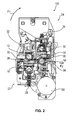
- FIG. 2 shows a partially sectional side view of a printing module 100 of a specific embodiment of the invention in the print mode. Elements having the same structure or function are identified with the same reference signs, as this is also the case in the further figures.
- a drive motor 58 which is coupled to the counter-pressure rollers 12, 14 via a gear stage serves to drive the counter-pressure rollers 12, 14. Guiding elements 30, 32, 34, 36 delimit the path of the thermal paper 20 through the printing module 100. For reasons of clarity, the thermal paper 20 is neither illustrated in Figure 2 nor in the further figures.
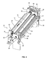
- Figure 3 shows the printing module 100 according to Figure 2 in the maintenance mode.
- the first unit 24 has been displaced along an oblong hole guide 56 provided in a first chassis 80 of the second unit 22.
- the oblong hole guide 56 has a first leg 57 and a second leg 55 which are connected to each other at one end and are angled relative to each other.
- the first unit 24 For displacement of the first unit 24 from the printing position into the maintenance position, the first unit 24 is guided in the direction of the arrow P4 along the first leg 57 of the oblong hole guide 56 via a pin 72 projecting from the first unit 24 into the oblong hole guide 56, is laterally displaced in the direction of the arrow P5 along the second leg 55 of the oblong hole guide 56 and is pivoted about an axis of rotation formed by the longitudinal axis of the pin 72.
- the second counter-pressure roller 12 is no longer held by means of the first unit 24 in its printing position in the second unit 22 and can be removed therefrom and thus also from the printing module 100.
- the second counter-pressure roller 12 By moving the first unit 24 from the printing position into the maintenance position, the second counter-pressure roller 12 only rests loosely on the thermal paper 20 or, respectively, on the second print head 16 so that a pressure force is present between the second print head 16 and the second counter-pressure roller 12 that is reduced compared to the print mode.
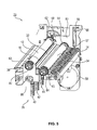
- FIG 4 a perspective illustration of the second unit 22 is shown.
- a second chassis 78 of the second unit 22 is illustrated in Figure 4 .
- a second oblong hole guide 86 is provided which is formed and arranged mirror-symmetrically with respect to the first oblong hole guide 56 in the first chassis 80.
- the normal vector of the mirror plane of symmetry of the mirror-symmetrical arrangement of the oblong hole guides 56, 86 runs parallel to the axes of rotation of the counter-pressure rollers 12, 14.
- a longitudinal axis of the widest thermal paper 20 to be printed lies in the plane of symmetry.
- each bearing unit is provided outside of the contact area contacting the thermal paper 20 in the print mode.
- Each of these bearing units comprises a first bearing 82, 84 and a second bearing 62, 63, 64.
- the second bearing 62, 63, 64 serves as an axial guide bearing and is located between the contact area and the first bearing.
- the first bearing 82, 84 serves to mount one end of the counter-pressure rollers 12, 14 in the chassis 78, 80 of the second unit 22.
- the second bearing 62, 63, 64 serves to couple the end regions of the respective counter-pressure roller 12, 14 to the print head 16, 18 lying opposite to the counter-pressure roller 12, 14.
- One guiding element 66, 68, 74, 76 each which is shown in Figure 6 and which is firmly connected to the first print head 16 or, respectively, the second print head 18 can be engaged with the second bearings 62, 63, 64 so that a relative motion between the print head 16, 18 and the counter-pressure roller 12, 14 is guided via the engagement between the guiding elements 66, 68 and the second bearing 62, 63, 64.
- the first bearings 82, 84 received in the second chassis 78 and the first bearings received in the first chassis allow a rotation of the counter-pressure rollers 12, 14 about their axes of rotation in the chassis 78, 80.
- the second bearings 62, 63, 64 allow a rotation of the counter-pressure rollers 12, 14 relative to the guiding elements 66, 68.
- limiting elements 32, 34, 38 are provided which extend over the maximally intended width of the thermal paper 20 to be printed. Together with the limiting elements 30, 36 shown in Figure 6 , they delimit the paper path of the thermal paper 20 through the printing module 100.
- the two limiting elements 32 and 38 are provided with a smooth surface, whereas the limiting elements 30, 34, 36 have a surface formed by longitudinal ribs.
- the limiting elements 30 to 38 are arranged such that each time a limiting element having a ribbed surface and a limiting element having a smooth surface are arranged opposite to each other in the print mode, and the thermal paper 20 is arranged between the surfaces of the limiting elements 30 to 38. This combination of unequal surfaces prevents that the moved thermal paper 20 gets stuck on the surfaces of the limiting elements 30 to 38 and, on the other hand, prevents damage to the thermal paper 20 and a paper jam possibly caused thereby.
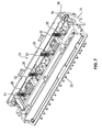
- FIG. 5 shows a further perspective view of the second unit 22.
- the second chassis 78 is not illustrated.
- the guiding elements 66, 68 which are firmly connected to the second print head 16 have a slot.
- the sides of the guiding element 66, 68 delimiting the slot engage with a groove provided in the circumferential surface of the second bearings 62, 63 in the print mode.
- the movement of the second print head 16 relative to the second counter-pressure roller 12 is guided so that it is guaranteed that the thermal line of the second print head 16 is pressed against the second counter-pressure roller 12. This allows a movement of the second print head 16 in the print mode as a result of the pressure forces generated by the spring element 28.
- the spring element 28 presses the thermal paper 20 against the second counter-pressure roller 12 with the aid of the second print head 16 and thus it presses the thermal line of the print head 16 against the thermal paper 20.
- the spring element 28 comprises four coil springs, of which the coil springs 40, 42, 44 are shown in Figure 5 , and which are uniformly distributed over the width of the printing area of the second print head 16.
- two second guide bearings 64, 65 are provided which are arranged at the end regions of the first counter-pressure roller 14.
- Two further guiding elements 74, 76 are connected to the first print head 18 and each have a slot. The sides of the guiding element 74, 76 delimiting the slot engage with a groove provided in the circumferential surface of the second bearings 64, 65 in the print mode. As a result thereof, the movement of the first print head 18 relative to the first counter-pressure roller 14 can be guided in the print mode in the same manner as this has already been described for the second print head 16 and the second counter-pressure roller 12.
- Figure 6 shows a perspective illustration of the first unit 24.
- One stop element 60, 61 each, integrated in the limiting element 30, serves to restrict the movement of the second counter-pressure roller 12 in the slots of the guiding elements 66, 68 in the direction of the first unit 24 in the print mode. By this restriction, preferably the position of the second counter-pressure roller 12 in an opening delimited by the slots of the guiding elements 66, 68 and the stop elements 60, 61 is fixed.
- the pin 72 of the first unit 24 engages with the oblong hole guide 56 in the first chassis 80 of the second unit 22.
- the first unit 24 has a second pin 70 which engages with the oblong hole guide 86 in the second chassis 78.
- the combination of oblong hole guides 56, 86 and pins 70, 72 allows a parallel guidance of the movement of the first unit 24 relative to the second unit 22 when changing between the printing position and the maintenance position.
- the guiding elements 74, 76 are firmly connected to the first print head 18 and have slots.
- the sides of the guiding element 74, 76 delimiting the slot engage with the grooves provided in the circumferential surfaces of the second bearings 64, 65 and guide the thermal line of the first print head 18 relative to the first counter-pressure roller 14.
- Figure 7 shows a further perspective view of the first unit 24 according to Figure 6 in which all four coil springs 48 to 54 of the spring element 26 which contact the first print head 18 at its side facing away from the thermal paper 20 are visible.
- each of the spring elements 26, 28 can also comprise more or less individual springs 40 to 54.
- other elastically deformable elements such as leaf springs or plastic blocks, in particular elastomer blocks, can be used.
Landscapes
- Printers Characterized By Their Purpose (AREA)
- Common Mechanisms (AREA)
- Electronic Switches (AREA)
Priority Applications (4)
| Application Number | Priority Date | Filing Date | Title |
|---|---|---|---|
| EP11161874.0A EP2511100B1 (fr) | 2011-04-11 | 2011-04-11 | Imprimante à double face pour imprimer les reçus sur un papier thermique |
| ES11161874.0T ES2528056T3 (es) | 2011-04-11 | 2011-04-11 | Impresora a doble cara para imprimir recibos sobre papel térmico |
| US14/110,542 US10576755B2 (en) | 2011-04-11 | 2012-04-11 | Double-sided printer for printing receipts on thermal paper |
| PCT/EP2012/056500 WO2012140030A1 (fr) | 2011-04-11 | 2012-04-11 | Imprimante recto/verso pour l'impression de reçus sur du papier thermique |
Applications Claiming Priority (1)
| Application Number | Priority Date | Filing Date | Title |
|---|---|---|---|
| EP11161874.0A EP2511100B1 (fr) | 2011-04-11 | 2011-04-11 | Imprimante à double face pour imprimer les reçus sur un papier thermique |
Publications (2)
| Publication Number | Publication Date |
|---|---|
| EP2511100A1 true EP2511100A1 (fr) | 2012-10-17 |
| EP2511100B1 EP2511100B1 (fr) | 2014-11-05 |
Family
ID=44533314
Family Applications (1)
| Application Number | Title | Priority Date | Filing Date |
|---|---|---|---|
| EP11161874.0A Active EP2511100B1 (fr) | 2011-04-11 | 2011-04-11 | Imprimante à double face pour imprimer les reçus sur un papier thermique |
Country Status (4)
| Country | Link |
|---|---|
| US (1) | US10576755B2 (fr) |
| EP (1) | EP2511100B1 (fr) |
| ES (1) | ES2528056T3 (fr) |
| WO (1) | WO2012140030A1 (fr) |
Cited By (1)
| Publication number | Priority date | Publication date | Assignee | Title |
|---|---|---|---|---|
| US11325405B2 (en) * | 2019-01-29 | 2022-05-10 | Fujitsu Component Limited | Printer with print head and support having head spring that urges print head |
Families Citing this family (1)
| Publication number | Priority date | Publication date | Assignee | Title |
|---|---|---|---|---|
| TWI636890B (zh) * | 2017-09-22 | 2018-10-01 | 東友科技股份有限公司 | 滾輪式側向力產生裝置 |
Citations (5)
| Publication number | Priority date | Publication date | Assignee | Title |
|---|---|---|---|---|
| EP1321296A2 (fr) | 2001-12-18 | 2003-06-25 | Ncr International Inc. | Imprimante thermique directe |
| US20070134039A1 (en) * | 2005-12-08 | 2007-06-14 | Ncr Corporation | Dual-sided thermal printing |
| EP2042327A2 (fr) * | 2007-09-28 | 2009-04-01 | Seiko Epson Corporation | Imprimante thermique |
| US7710442B2 (en) | 2006-03-07 | 2010-05-04 | Ncr Corporation | Two-sided thermal print configurations |
| WO2010070933A1 (fr) * | 2008-12-19 | 2010-06-24 | 株式会社サトー | Imprimante thermique à impression recto-verso |
Family Cites Families (3)
| Publication number | Priority date | Publication date | Assignee | Title |
|---|---|---|---|---|
| US7828490B2 (en) * | 2006-05-31 | 2010-11-09 | Toshiba Tec Kabushiki Kaisha | Printing apparatus including a cover holding a thermal head and a platen roller on a hinged frame |
| US20080003039A1 (en) * | 2006-06-29 | 2008-01-03 | Toshiba Tec Kabushiki Kaisha | Printer |
| JP2011201017A (ja) * | 2010-03-24 | 2011-10-13 | Seiko Epson Corp | プリンター |
-
2011
- 2011-04-11 EP EP11161874.0A patent/EP2511100B1/fr active Active
- 2011-04-11 ES ES11161874.0T patent/ES2528056T3/es active Active
-
2012
- 2012-04-11 US US14/110,542 patent/US10576755B2/en active Active
- 2012-04-11 WO PCT/EP2012/056500 patent/WO2012140030A1/fr not_active Ceased
Patent Citations (6)
| Publication number | Priority date | Publication date | Assignee | Title |
|---|---|---|---|---|
| EP1321296A2 (fr) | 2001-12-18 | 2003-06-25 | Ncr International Inc. | Imprimante thermique directe |
| US6784906B2 (en) | 2001-12-18 | 2004-08-31 | Ncr Corporation | Direct thermal printer |
| US20070134039A1 (en) * | 2005-12-08 | 2007-06-14 | Ncr Corporation | Dual-sided thermal printing |
| US7710442B2 (en) | 2006-03-07 | 2010-05-04 | Ncr Corporation | Two-sided thermal print configurations |
| EP2042327A2 (fr) * | 2007-09-28 | 2009-04-01 | Seiko Epson Corporation | Imprimante thermique |
| WO2010070933A1 (fr) * | 2008-12-19 | 2010-06-24 | 株式会社サトー | Imprimante thermique à impression recto-verso |
Cited By (1)
| Publication number | Priority date | Publication date | Assignee | Title |
|---|---|---|---|---|
| US11325405B2 (en) * | 2019-01-29 | 2022-05-10 | Fujitsu Component Limited | Printer with print head and support having head spring that urges print head |
Also Published As
| Publication number | Publication date |
|---|---|
| EP2511100B1 (fr) | 2014-11-05 |
| ES2528056T3 (es) | 2015-02-03 |
| US10576755B2 (en) | 2020-03-03 |
| US20140049592A1 (en) | 2014-02-20 |
| WO2012140030A1 (fr) | 2012-10-18 |
Similar Documents
| Publication | Publication Date | Title |
|---|---|---|
| EP1872958B1 (fr) | Imprimante thermique et dispositif d'impression | |
| CN103702918B (zh) | 介质处理装置及相关系统 | |
| US9302509B2 (en) | Media processing device with enhanced media and ribbon loading and unloading features | |
| KR940005321B1 (ko) | 서어멀 프린터 | |
| EP2511100B1 (fr) | Imprimante à double face pour imprimer les reçus sur un papier thermique | |
| KR101870439B1 (ko) | 기록 매체 처리 장치 | |
| CN102120389B (zh) | 记录装置及记录装置的记录介质供给结构 | |
| JP6023666B2 (ja) | 長尺シート体保持装置およびプリンタ | |
| EP2096058A2 (fr) | Dispositif de transport de feuille et appareil d'enregistrement d'images | |
| KR100581354B1 (ko) | 써멀프린터의 써멀프린터헤드 정렬장치 | |
| JP5450166B2 (ja) | 移送印字媒体スタンプ装置および移送印字媒体スタンプ方法 | |
| CN110421983B (zh) | 热敏打印机 | |
| JP2015129028A (ja) | ロール状記録媒体保持機構、ロール給紙装置及び画像形成装置 | |
| US9481183B2 (en) | Printer | |
| JP6116377B2 (ja) | プリンタ | |
| JP5438706B2 (ja) | 画像形成装置及びヘッド離間制御方法 | |
| JP2013178615A (ja) | 通帳伝票プリンタ装置 | |
| JP7477582B1 (ja) | 媒体搬送機構及びプリンタ | |
| US8833756B2 (en) | Sheet-shaped medium feeding device and sheet-shaped medium processing device | |
| CN118358262A (zh) | 打印机设备及其使用方法 | |
| JP7459513B2 (ja) | 印刷装置 | |
| JP5341913B2 (ja) | 搬送装置及びプリンタ | |
| JPH06238967A (ja) | 通帳類印字装置 | |
| JP5959408B2 (ja) | プリンタ | |
| JP6074333B2 (ja) | プリンタ |
Legal Events
| Date | Code | Title | Description |
|---|---|---|---|
| PUAI | Public reference made under article 153(3) epc to a published international application that has entered the european phase |
Free format text: ORIGINAL CODE: 0009012 |
|
| AK | Designated contracting states |
Kind code of ref document: A1 Designated state(s): AL AT BE BG CH CY CZ DE DK EE ES FI FR GB GR HR HU IE IS IT LI LT LU LV MC MK MT NL NO PL PT RO RS SE SI SK SM TR |
|
| AX | Request for extension of the european patent |
Extension state: BA ME |
|
| 17P | Request for examination filed |
Effective date: 20130408 |
|
| GRAP | Despatch of communication of intention to grant a patent |
Free format text: ORIGINAL CODE: EPIDOSNIGR1 |
|
| INTG | Intention to grant announced |
Effective date: 20131216 |
|
| GRAS | Grant fee paid |
Free format text: ORIGINAL CODE: EPIDOSNIGR3 |
|
| GRAA | (expected) grant |
Free format text: ORIGINAL CODE: 0009210 |
|
| AK | Designated contracting states |
Kind code of ref document: B1 Designated state(s): AL AT BE BG CH CY CZ DE DK EE ES FI FR GB GR HR HU IE IS IT LI LT LU LV MC MK MT NL NO PL PT RO RS SE SI SK SM TR |
|
| REG | Reference to a national code |
Ref country code: GB Ref legal event code: FG4D |
|
| REG | Reference to a national code |
Ref country code: CH Ref legal event code: EP |
|
| REG | Reference to a national code |
Ref country code: AT Ref legal event code: REF Ref document number: 694388 Country of ref document: AT Kind code of ref document: T Effective date: 20141115 |
|
| REG | Reference to a national code |
Ref country code: SE Ref legal event code: TRGR |
|
| REG | Reference to a national code |
Ref country code: IE Ref legal event code: FG4D |
|
| REG | Reference to a national code |
Ref country code: DE Ref legal event code: R096 Ref document number: 602011011041 Country of ref document: DE Effective date: 20141218 |
|
| REG | Reference to a national code |
Ref country code: ES Ref legal event code: FG2A Ref document number: 2528056 Country of ref document: ES Kind code of ref document: T3 Effective date: 20150203 |
|
| REG | Reference to a national code |
Ref country code: NL Ref legal event code: T3 |
|
| REG | Reference to a national code |
Ref country code: LT Ref legal event code: MG4D |
|
| PG25 | Lapsed in a contracting state [announced via postgrant information from national office to epo] |
Ref country code: PT Free format text: LAPSE BECAUSE OF FAILURE TO SUBMIT A TRANSLATION OF THE DESCRIPTION OR TO PAY THE FEE WITHIN THE PRESCRIBED TIME-LIMIT Effective date: 20150305 Ref country code: LT Free format text: LAPSE BECAUSE OF FAILURE TO SUBMIT A TRANSLATION OF THE DESCRIPTION OR TO PAY THE FEE WITHIN THE PRESCRIBED TIME-LIMIT Effective date: 20141105 Ref country code: IS Free format text: LAPSE BECAUSE OF FAILURE TO SUBMIT A TRANSLATION OF THE DESCRIPTION OR TO PAY THE FEE WITHIN THE PRESCRIBED TIME-LIMIT Effective date: 20150305 Ref country code: NO Free format text: LAPSE BECAUSE OF FAILURE TO SUBMIT A TRANSLATION OF THE DESCRIPTION OR TO PAY THE FEE WITHIN THE PRESCRIBED TIME-LIMIT Effective date: 20150205 Ref country code: FI Free format text: LAPSE BECAUSE OF FAILURE TO SUBMIT A TRANSLATION OF THE DESCRIPTION OR TO PAY THE FEE WITHIN THE PRESCRIBED TIME-LIMIT Effective date: 20141105 |
|
| PG25 | Lapsed in a contracting state [announced via postgrant information from national office to epo] |
Ref country code: HR Free format text: LAPSE BECAUSE OF FAILURE TO SUBMIT A TRANSLATION OF THE DESCRIPTION OR TO PAY THE FEE WITHIN THE PRESCRIBED TIME-LIMIT Effective date: 20141105 Ref country code: CY Free format text: LAPSE BECAUSE OF FAILURE TO SUBMIT A TRANSLATION OF THE DESCRIPTION OR TO PAY THE FEE WITHIN THE PRESCRIBED TIME-LIMIT Effective date: 20141105 Ref country code: LV Free format text: LAPSE BECAUSE OF FAILURE TO SUBMIT A TRANSLATION OF THE DESCRIPTION OR TO PAY THE FEE WITHIN THE PRESCRIBED TIME-LIMIT Effective date: 20141105 Ref country code: GR Free format text: LAPSE BECAUSE OF FAILURE TO SUBMIT A TRANSLATION OF THE DESCRIPTION OR TO PAY THE FEE WITHIN THE PRESCRIBED TIME-LIMIT Effective date: 20150206 Ref country code: PL Free format text: LAPSE BECAUSE OF FAILURE TO SUBMIT A TRANSLATION OF THE DESCRIPTION OR TO PAY THE FEE WITHIN THE PRESCRIBED TIME-LIMIT Effective date: 20141105 Ref country code: RS Free format text: LAPSE BECAUSE OF FAILURE TO SUBMIT A TRANSLATION OF THE DESCRIPTION OR TO PAY THE FEE WITHIN THE PRESCRIBED TIME-LIMIT Effective date: 20141105 |
|
| PG25 | Lapsed in a contracting state [announced via postgrant information from national office to epo] |
Ref country code: DK Free format text: LAPSE BECAUSE OF FAILURE TO SUBMIT A TRANSLATION OF THE DESCRIPTION OR TO PAY THE FEE WITHIN THE PRESCRIBED TIME-LIMIT Effective date: 20141105 Ref country code: CZ Free format text: LAPSE BECAUSE OF FAILURE TO SUBMIT A TRANSLATION OF THE DESCRIPTION OR TO PAY THE FEE WITHIN THE PRESCRIBED TIME-LIMIT Effective date: 20141105 Ref country code: EE Free format text: LAPSE BECAUSE OF FAILURE TO SUBMIT A TRANSLATION OF THE DESCRIPTION OR TO PAY THE FEE WITHIN THE PRESCRIBED TIME-LIMIT Effective date: 20141105 Ref country code: SK Free format text: LAPSE BECAUSE OF FAILURE TO SUBMIT A TRANSLATION OF THE DESCRIPTION OR TO PAY THE FEE WITHIN THE PRESCRIBED TIME-LIMIT Effective date: 20141105 |
|
| REG | Reference to a national code |
Ref country code: DE Ref legal event code: R097 Ref document number: 602011011041 Country of ref document: DE |
|
| PLBE | No opposition filed within time limit |
Free format text: ORIGINAL CODE: 0009261 |
|
| STAA | Information on the status of an ep patent application or granted ep patent |
Free format text: STATUS: NO OPPOSITION FILED WITHIN TIME LIMIT |
|
| 26N | No opposition filed |
Effective date: 20150806 |
|
| PG25 | Lapsed in a contracting state [announced via postgrant information from national office to epo] |
Ref country code: MC Free format text: LAPSE BECAUSE OF FAILURE TO SUBMIT A TRANSLATION OF THE DESCRIPTION OR TO PAY THE FEE WITHIN THE PRESCRIBED TIME-LIMIT Effective date: 20141105 Ref country code: LU Free format text: LAPSE BECAUSE OF FAILURE TO SUBMIT A TRANSLATION OF THE DESCRIPTION OR TO PAY THE FEE WITHIN THE PRESCRIBED TIME-LIMIT Effective date: 20150411 |
|
| REG | Reference to a national code |
Ref country code: CH Ref legal event code: PL |
|
| REG | Reference to a national code |
Ref country code: IE Ref legal event code: MM4A |
|
| PG25 | Lapsed in a contracting state [announced via postgrant information from national office to epo] |
Ref country code: LI Free format text: LAPSE BECAUSE OF NON-PAYMENT OF DUE FEES Effective date: 20150430 Ref country code: CH Free format text: LAPSE BECAUSE OF NON-PAYMENT OF DUE FEES Effective date: 20150430 |
|
| PG25 | Lapsed in a contracting state [announced via postgrant information from national office to epo] |
Ref country code: SI Free format text: LAPSE BECAUSE OF FAILURE TO SUBMIT A TRANSLATION OF THE DESCRIPTION OR TO PAY THE FEE WITHIN THE PRESCRIBED TIME-LIMIT Effective date: 20141105 |
|
| REG | Reference to a national code |
Ref country code: FR Ref legal event code: PLFP Year of fee payment: 6 |
|
| PG25 | Lapsed in a contracting state [announced via postgrant information from national office to epo] |
Ref country code: IE Free format text: LAPSE BECAUSE OF NON-PAYMENT OF DUE FEES Effective date: 20150411 |
|
| PG25 | Lapsed in a contracting state [announced via postgrant information from national office to epo] |
Ref country code: RO Free format text: LAPSE BECAUSE OF FAILURE TO SUBMIT A TRANSLATION OF THE DESCRIPTION OR TO PAY THE FEE WITHIN THE PRESCRIBED TIME-LIMIT Effective date: 20141105 |
|
| REG | Reference to a national code |
Ref country code: AT Ref legal event code: UEP Ref document number: 694388 Country of ref document: AT Kind code of ref document: T Effective date: 20141105 |
|
| PG25 | Lapsed in a contracting state [announced via postgrant information from national office to epo] |
Ref country code: MT Free format text: LAPSE BECAUSE OF FAILURE TO SUBMIT A TRANSLATION OF THE DESCRIPTION OR TO PAY THE FEE WITHIN THE PRESCRIBED TIME-LIMIT Effective date: 20141105 |
|
| REG | Reference to a national code |
Ref country code: FR Ref legal event code: PLFP Year of fee payment: 7 |
|
| PG25 | Lapsed in a contracting state [announced via postgrant information from national office to epo] |
Ref country code: HU Free format text: LAPSE BECAUSE OF FAILURE TO SUBMIT A TRANSLATION OF THE DESCRIPTION OR TO PAY THE FEE WITHIN THE PRESCRIBED TIME-LIMIT; INVALID AB INITIO Effective date: 20110411 Ref country code: SM Free format text: LAPSE BECAUSE OF FAILURE TO SUBMIT A TRANSLATION OF THE DESCRIPTION OR TO PAY THE FEE WITHIN THE PRESCRIBED TIME-LIMIT Effective date: 20141105 Ref country code: BG Free format text: LAPSE BECAUSE OF FAILURE TO SUBMIT A TRANSLATION OF THE DESCRIPTION OR TO PAY THE FEE WITHIN THE PRESCRIBED TIME-LIMIT Effective date: 20141105 |
|
| PG25 | Lapsed in a contracting state [announced via postgrant information from national office to epo] |
Ref country code: TR Free format text: LAPSE BECAUSE OF FAILURE TO SUBMIT A TRANSLATION OF THE DESCRIPTION OR TO PAY THE FEE WITHIN THE PRESCRIBED TIME-LIMIT Effective date: 20141105 |
|
| PG25 | Lapsed in a contracting state [announced via postgrant information from national office to epo] |
Ref country code: BE Free format text: LAPSE BECAUSE OF FAILURE TO SUBMIT A TRANSLATION OF THE DESCRIPTION OR TO PAY THE FEE WITHIN THE PRESCRIBED TIME-LIMIT Effective date: 20141105 |
|
| REG | Reference to a national code |
Ref country code: FR Ref legal event code: PLFP Year of fee payment: 8 |
|
| PG25 | Lapsed in a contracting state [announced via postgrant information from national office to epo] |
Ref country code: MK Free format text: LAPSE BECAUSE OF FAILURE TO SUBMIT A TRANSLATION OF THE DESCRIPTION OR TO PAY THE FEE WITHIN THE PRESCRIBED TIME-LIMIT Effective date: 20141105 |
|
| PG25 | Lapsed in a contracting state [announced via postgrant information from national office to epo] |
Ref country code: AL Free format text: LAPSE BECAUSE OF FAILURE TO SUBMIT A TRANSLATION OF THE DESCRIPTION OR TO PAY THE FEE WITHIN THE PRESCRIBED TIME-LIMIT Effective date: 20141105 |
|
| PGFP | Annual fee paid to national office [announced via postgrant information from national office to epo] |
Ref country code: AT Payment date: 20190325 Year of fee payment: 9 |
|
| PGFP | Annual fee paid to national office [announced via postgrant information from national office to epo] |
Ref country code: SE Payment date: 20200320 Year of fee payment: 10 Ref country code: NL Payment date: 20200319 Year of fee payment: 10 |
|
| PGFP | Annual fee paid to national office [announced via postgrant information from national office to epo] |
Ref country code: ES Payment date: 20200504 Year of fee payment: 10 |
|
| PGFP | Annual fee paid to national office [announced via postgrant information from national office to epo] |
Ref country code: IT Payment date: 20200318 Year of fee payment: 10 |
|
| REG | Reference to a national code |
Ref country code: AT Ref legal event code: MM01 Ref document number: 694388 Country of ref document: AT Kind code of ref document: T Effective date: 20200411 |
|
| PG25 | Lapsed in a contracting state [announced via postgrant information from national office to epo] |
Ref country code: AT Free format text: LAPSE BECAUSE OF NON-PAYMENT OF DUE FEES Effective date: 20200411 |
|
| REG | Reference to a national code |
Ref country code: SE Ref legal event code: EUG |
|
| REG | Reference to a national code |
Ref country code: NL Ref legal event code: MM Effective date: 20210501 |
|
| PG25 | Lapsed in a contracting state [announced via postgrant information from national office to epo] |
Ref country code: SE Free format text: LAPSE BECAUSE OF NON-PAYMENT OF DUE FEES Effective date: 20210412 |
|
| PG25 | Lapsed in a contracting state [announced via postgrant information from national office to epo] |
Ref country code: NL Free format text: LAPSE BECAUSE OF NON-PAYMENT OF DUE FEES Effective date: 20210501 |
|
| REG | Reference to a national code |
Ref country code: ES Ref legal event code: FD2A Effective date: 20220701 |
|
| PG25 | Lapsed in a contracting state [announced via postgrant information from national office to epo] |
Ref country code: ES Free format text: LAPSE BECAUSE OF NON-PAYMENT OF DUE FEES Effective date: 20210412 |
|
| REG | Reference to a national code |
Ref country code: FR Ref legal event code: PLFP Year of fee payment: 13 |
|
| REG | Reference to a national code |
Ref country code: GB Ref legal event code: 732E Free format text: REGISTERED BETWEEN 20230323 AND 20230329 |
|
| PG25 | Lapsed in a contracting state [announced via postgrant information from national office to epo] |
Ref country code: IT Free format text: LAPSE BECAUSE OF NON-PAYMENT OF DUE FEES Effective date: 20200411 |
|
| REG | Reference to a national code |
Ref country code: GB Ref legal event code: 732E Free format text: REGISTERED BETWEEN 20230525 AND 20230601 |
|
| REG | Reference to a national code |
Ref country code: DE Ref legal event code: R081 Ref document number: 602011011041 Country of ref document: DE Owner name: DIEBOLD NIXDORF SYSTEMS GMBH, DE Free format text: FORMER OWNER: WINCOR NIXDORF INTERNATIONAL GMBH, 33106 PADERBORN, DE |
|
| PGFP | Annual fee paid to national office [announced via postgrant information from national office to epo] |
Ref country code: DE Payment date: 20250319 Year of fee payment: 15 |
|
| PG25 | Lapsed in a contracting state [announced via postgrant information from national office to epo] |
Ref country code: IT Free format text: LAPSE BECAUSE OF NON-PAYMENT OF DUE FEES Effective date: 20210411 |
|
| PGFP | Annual fee paid to national office [announced via postgrant information from national office to epo] |
Ref country code: GB Payment date: 20260319 Year of fee payment: 16 |
|
| PGFP | Annual fee paid to national office [announced via postgrant information from national office to epo] |
Ref country code: FR Payment date: 20260320 Year of fee payment: 16 |