EP2511201A1 - Dispositif d'alimentation vibrant de forme plan circulaire - Google Patents
Dispositif d'alimentation vibrant de forme plan circulaire Download PDFInfo
- Publication number
- EP2511201A1 EP2511201A1 EP12163641A EP12163641A EP2511201A1 EP 2511201 A1 EP2511201 A1 EP 2511201A1 EP 12163641 A EP12163641 A EP 12163641A EP 12163641 A EP12163641 A EP 12163641A EP 2511201 A1 EP2511201 A1 EP 2511201A1
- Authority
- EP
- European Patent Office
- Prior art keywords
- tub
- rotation
- pivot
- axis
- paddle
- Prior art date
- Legal status (The legal status is an assumption and is not a legal conclusion. Google has not performed a legal analysis and makes no representation as to the accuracy of the status listed.)
- Withdrawn
Links
- 230000005540 biological transmission Effects 0.000 claims abstract description 9
- 230000000750 progressive effect Effects 0.000 claims abstract description 6
- 230000009471 action Effects 0.000 description 4
- 230000009849 deactivation Effects 0.000 description 3
- 230000004913 activation Effects 0.000 description 2
- 230000000670 limiting effect Effects 0.000 description 2
- 230000004048 modification Effects 0.000 description 2
- 238000012986 modification Methods 0.000 description 2
- 230000002860 competitive effect Effects 0.000 description 1
- 230000000694 effects Effects 0.000 description 1
- 230000000284 resting effect Effects 0.000 description 1
- 238000000926 separation method Methods 0.000 description 1
Images



Classifications
-
- B—PERFORMING OPERATIONS; TRANSPORTING
- B65—CONVEYING; PACKING; STORING; HANDLING THIN OR FILAMENTARY MATERIAL
- B65G—TRANSPORT OR STORAGE DEVICES, e.g. CONVEYORS FOR LOADING OR TIPPING, SHOP CONVEYOR SYSTEMS OR PNEUMATIC TUBE CONVEYORS
- B65G27/00—Jigging conveyors
- B65G27/02—Jigging conveyors comprising helical or spiral channels or conduits for elevation of materials
-
- B—PERFORMING OPERATIONS; TRANSPORTING
- B65—CONVEYING; PACKING; STORING; HANDLING THIN OR FILAMENTARY MATERIAL
- B65G—TRANSPORT OR STORAGE DEVICES, e.g. CONVEYORS FOR LOADING OR TIPPING, SHOP CONVEYOR SYSTEMS OR PNEUMATIC TUBE CONVEYORS
- B65G47/00—Article or material-handling devices associated with conveyors; Methods employing such devices
- B65G47/02—Devices for feeding articles or materials to conveyors
- B65G47/04—Devices for feeding articles or materials to conveyors for feeding articles
- B65G47/12—Devices for feeding articles or materials to conveyors for feeding articles from disorderly-arranged article piles or from loose assemblages of articles
- B65G47/14—Devices for feeding articles or materials to conveyors for feeding articles from disorderly-arranged article piles or from loose assemblages of articles arranging or orientating the articles by mechanical or pneumatic means during feeding
- B65G47/1407—Devices for feeding articles or materials to conveyors for feeding articles from disorderly-arranged article piles or from loose assemblages of articles arranging or orientating the articles by mechanical or pneumatic means during feeding the articles being fed from a container, e.g. a bowl
- B65G47/1414—Devices for feeding articles or materials to conveyors for feeding articles from disorderly-arranged article piles or from loose assemblages of articles arranging or orientating the articles by mechanical or pneumatic means during feeding the articles being fed from a container, e.g. a bowl by means of movement of at least the whole wall of the container
- B65G47/1421—Vibratory movement
Definitions
- the present invention relates to a vibrating feeder with circular plan shape, with improved efficiency.
- automated production lines use vibrating feeders which have the function of supplying the production line with a preset quantity of components, optionally also with a preset orientation, if required by the line.
- vibrating feeders with circular plan shape are known which are composed substantially of a footing which supports a container or tub or bowl which has a circular plan shape and is arranged generally so that its axis is vertical.
- the tub is supported by the footing so that it can rotate about its own axis and actuation means act thereon and cause its alternating rotation about its own axis with respect to the footing.
- actuation means act thereon and cause its alternating rotation about its own axis with respect to the footing.
- a conveyance track is provided, which extends from the bottom of the tub to its top, where it is connected to the line to be fed.
- the conveyance track is extended in a helical shape on the internal lateral surface of the tub and the actuation means act on the tub so as to cause its rotation, with respect to the footing, about its own axis in one direction of rotation, or forward rotation, which matches the advancement of the objects from the bottom toward the top of the tub along the conveyance track, alternated with a rotation in the opposite direction, or return rotation.
- the return rotation of the tub is performed at a speed which is considerably higher than the rotation rate during the forward rotation, so as to achieve the separation of the objects from the conveyance track.
- the objects placed on the conveyance track, during forward rotation, are substantially integral with the conveyance track, while during the return rotation they separate from the conveyance track, which retracts, and then reengage the conveyance track at a more advanced point of the track when the direction of rotation of the tub is reversed again, thus achieving the progressive advancement of the objects along the conveyance track.
- the tub is supported by the footing by means of leaf springs, which are arranged around the axis of the tub and are inclined with respect to such axis.
- An electromagnetic actuator is arranged between the footing and the tub and can be actuated to lower the tub toward the footing in contrast with the action of the leaf springs.
- the activation of the electromagnet causes the very swift lowering of the tub and the loading of the leaf springs, which by being inclined cause the rotation of the tub in one direction of rotation (return rotation).
- the deactivation of the electromagnet releases the leaf springs, which discharge, causing the rotation of the tube in the opposite direction of rotation (forward rotation).
- the lack of efficiency in supplying the line can be ascribed to the shape or to the material of the objects to be fed, which facilitates clumping of the objects, which, being tied together, are made to fall back into the tub, or to poor friction between the objects and the conveyance track, which prevents their advancement along the conveyance track.
- the aim of the present invention is to solve the above mentioned problems, by providing a vibrating feeder with circular plan shape which has a higher efficiency than vibrating feeders with circular plan shape of the known type.
- an object of the invention is to provide a vibrating feeder that ensures the correct feeding of objects to a line regardless of the shape and material of the objects to be fed.
- Another object of the invention is to provide a vibrating feeder that can be derived, with modifications that are simple to provide, from vibrating feeders of the known type.
- Another object of the invention is to provide a vibrating feeder that can be manufactured at competitive costs.
- a vibrating feeder with circular plan shape comprising a footing which supports a tub having a circular plan shape, at least one conveyance track being provided in said tub and extending from the bottom of said tub toward the top of said tub, means being provided for the actuation of said tub with a vibrating motion composed of at least one alternating rotation about its axis, with respect to said footing, for the progressive advancement, along said conveyance track, of objects arranged in said tub, characterized in that it comprises:
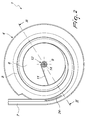
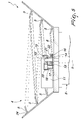
- the feeder according to the invention comprises, in a per se known manner, a footing 2, which is provided with feet 3 for resting on the ground, and a tub 4 having a circular plan shape, which is supported by the footing 2.
- At least one conveyance track 5 is provided, which extends from the bottom 6 of the tub 4 toward the top of the tub 4, where it is connected to a connecting member 7, by way of which it can be connected to the line that is to be fed by means of objects, not shown, which are arranged in the tub 4.
- the feeder 1 further comprises means 8 for actuating the tub 4, with respect to the footing 2, with a vibrating motion which is composed of at least one alternated rotation about its own axis 9 so as to cause the progressive advancement, along the conveyance track 5, of the objects arranged in the tub 4.
- the feeder 1 comprises: a pivot 10, which is jointly connected to the tub 4 and is arranged coaxially to the tub 4, at least one paddle 11, which is associated with the pivot 10 and is extended radially with respect to the pivot 10, and means 12 for the unidirectional transmission of the rotation of the pivot 10 to the paddle 11 to achieve a rotation, always in a same direction of rotation, of the paddle 11 about the axis 9 with respect to the footing 2 by means of the alternating rotation of the tub 4 about the axis 9 with respect to the footing 2.
- the pivot 10 is fixed to the bottom 6 of the tub 4.
- the tub 4 is arranged so that its axis 9 is substantially vertical and can be supported by the footing 2 so as to be able to rotate, with an alternating rotary motion, about the axis 9, for example, as shown, by interposing between the footing 2 and the tub 4 leaf springs 13 which are arranged around the axis 9 and are inclined with respect to the axis 9 so that a lowering of the tub 4 with respect to the footing 2 also causes a rotation of the tub 4 about the axis 9 with respect to the footing 2 and a lifting of the tub 4 with respect to the footing 2 causes a rotation of the tub 4 about the axis 9 with respect to the footing 2 in the opposite direction.
- the actuation means 8 can be constituted, in a per se known manner, by an electromagnet which is interposed between the footing 2 and the tub 4 and can be activated to cause the lowering of the tub 4 in contrast with the action of the leaf springs 13, as will become better apparent hereinafter.
- the unidirectional transmission means 12 comprise a free wheel 14, which is arranged between the pivot 10 and the paddle 11.
- the tub 4 has a substantially cylindrical or frustum-like shape, with the larger end face open and directed upward, as shown, and the conveyance track 5 is extended in a helix on the internal side walls of the tub 4 starting from the bottom 6 and rises progressively toward the top of the tub 4.
- the alternating rotation of the tub 4 about its axis 9 with respect to the footing 2 comprises, in sequence, a forward rotation in one direction of rotation, which is adapted to move the objects arranged on the conveyance track 5 jointly with the conveyance track 5, and a return rotation, in the opposite direction of rotation, which is adapted to move the conveyance track 5 backwards with respect to the objects arranged thereon.
- the unidirectional transmission means 12 are adapted to couple, in rotation about the axis 9, the paddle 11 and the pivot 10 during the forward rotation and to disengage, in rotation about the axis 9, the paddle 11 and the pivot 10 during the return rotation of the tub 4 with respect to the footing 2.
- the rotation rate of the paddle 11 can be different from the rotation rate of the pivot 10 during forward rotation, providing, as shown in the variation provided in Figure 5 , between the free wheel 14 and the paddle 11, a speed variator 15, which is constituted preferably by a gear-type variator.
- the speed variator 15 is constituted by a step-up unit so as to obtain, for the paddle 11, a rotation rate which is higher than the rotation rate of the pivot 10 about the axis 9.
- a free wheel 14 is mounted around the pivot 10 and a first gear 16 is fixed around the free wheel 14 and meshes with a second free wheel 17, which is integral and coaxial with respect to a shaft 18 which, by means of an arm 19, is supported by the pivot 10.
- a third gear 20 is fixed coaxially to the shaft 8 and meshes with a fourth gear 21 which is coaxial to the pivot 10 and to which the paddle 11 is connected.
- a bearing 22 is interposed between the fourth gear 21 and the pivot 10.
- the paddle 11 or paddles 11 can affect only the region of the tub that is not occupied by the conveyance track 5 or can affect the conveyance track 5 as well.
- the paddle or paddles 11 can be pivoted to the side of the free wheel 14 about an axis which is perpendicular to the axis 9, so as to be able to follow, for at least one portion, the conveyance track 5, which can have adapted recesses to allow the paddle 11 or the paddles 11 to return toward the lower part of the tub 4.
- the upper end of the conveyance track 5 is connected to the connecting member 7, which exits from the tub 4 and can be used to connect the feeder 1 to the line to be supplied.
- the connecting member 7 devices or particular shapes can be provided for selecting and/or orienting, in a per se known manner, the objects to be fed.
- the embodiment shown illustrates a contoured slot 24 into which the objects, constituted for example by objects composed of a stem with an expanded end which is larger than the contoured slot 24, can fall, remaining in any case suspended from the conveyance track 5 and the connecting member 7 by means of the expanded end, in order to be fed to the line in a preset position.
- the objects to be fed are poured haphazardly into the tub 4.
- the vibration of the tub 4, i.e., its alternating rotation about the axis 9, causes the progressive advancement of the objects along the conveyance track 5 toward the connecting member 7 and therefore toward the line to be fed.
- the actuation of the electromagnet 8 causes the very quick lowering of the tub 4 and the arrangement of the leaf springs 13 converts this lowering motion into a rotary motion (return rotation) of the tub 4 about the axis 9 with respect to the footing 2 with a direction of rotation (counterclockwise in the figures) which is opposite with respect to forward direction (clockwise in the figures) to be imparted to the objects along the conveyance track 5.
- the deactivation of the electromagnet 8 causes, through the action of the leaf springs 13, a rotation of the tub 4, with respect to the footing 2, which is generally slower than the return rotation, with a rotary motion about the axis 9 in the direction of rotation that matches the advancement direction to be imparted to the objects (forward rotation).
- the return rotation, caused by the activation of the electromagnet 8, is so fast that it moves the conveyance track 5, in the opposite direction with respect to the advancement direction of the objects, with respect to the objects, which remain practically stationary during the return rotation and which, when the tub 4 reverses the direction of rotation due to the action of the leaf springs 13, following the deactivation of the electromagnet 8, rest on a more advanced point of the conveyance track 5.
- the free wheel 14 rigidly couples the paddle 11 to the pivot 10 in rotation about the axis 9 and therefore the paddle 11 rotates jointly with the pivot 10 inside the tub 4, assisting the rise of the objects on the conveyance track 5.
- the alternating motion of the pivot 10 about its own axis 9 leads to a rotary motion, in a single direction of rotation, of the paddle 11, which assists the advancement of the objects along the conveyance track 5, increasing the efficiency of the feeder.
- the feeder according to the invention fully achieves the intended aim, since it has a higher efficiency than conventional types of vibrating feeder.
- the higher efficiency leads to higher productivity and/or to an energy saving.
- the actuation means for causing the alternating rotation of the tub 4 about its own axis instead of being constituted by the electromagnet 8 and by leaf springs 13, as shown, can be constituted by other actuation means of the known type, such as for example piezoelectric actuators or other actuation means.
- the materials used, as well as the dimensions, may be any according to requirements and to the state of the art.
Landscapes
- Engineering & Computer Science (AREA)
- Mechanical Engineering (AREA)
- Catching Or Destruction (AREA)
- Apparatuses For Generation Of Mechanical Vibrations (AREA)
- Jigging Conveyors (AREA)
Applications Claiming Priority (1)
| Application Number | Priority Date | Filing Date | Title |
|---|---|---|---|
| IT000637A ITMI20110637A1 (it) | 2011-04-14 | 2011-04-14 | Alimentatore vibrante a pianta circolare, ad efficienza incrementata. |
Publications (1)
| Publication Number | Publication Date |
|---|---|
| EP2511201A1 true EP2511201A1 (fr) | 2012-10-17 |
Family
ID=44553951
Family Applications (1)
| Application Number | Title | Priority Date | Filing Date |
|---|---|---|---|
| EP12163641A Withdrawn EP2511201A1 (fr) | 2011-04-14 | 2012-04-10 | Dispositif d'alimentation vibrant de forme plan circulaire |
Country Status (2)
| Country | Link |
|---|---|
| EP (1) | EP2511201A1 (fr) |
| IT (1) | ITMI20110637A1 (fr) |
Cited By (12)
| Publication number | Priority date | Publication date | Assignee | Title |
|---|---|---|---|---|
| CN103922087A (zh) * | 2014-04-25 | 2014-07-16 | 苏州源硕精密模具有限公司 | 扁平物料翻转排序装置 |
| CN103922125A (zh) * | 2014-04-25 | 2014-07-16 | 苏州源硕精密模具有限公司 | 钉形物料自动排序装置 |
| CN103922122A (zh) * | 2014-04-25 | 2014-07-16 | 苏州源硕精密模具有限公司 | 重心偏离物料排序振动盘 |
| CN103922088A (zh) * | 2014-04-25 | 2014-07-16 | 苏州源硕精密模具有限公司 | 不规则物料排序振动盘 |
| CN104249278A (zh) * | 2013-06-28 | 2014-12-31 | 江苏天工工具有限公司 | 一种无心磨床的新型送料装置 |
| CN104310031A (zh) * | 2014-10-23 | 2015-01-28 | 中国农业大学 | 嫁接套管自动排列输送装置 |
| CN104828522A (zh) * | 2015-03-26 | 2015-08-12 | 歌尔声学股份有限公司 | 一种轴类零件供料装置 |
| CN105346944A (zh) * | 2015-11-25 | 2016-02-24 | 苏州源硕精密模具有限公司 | 一种适用于钉形物料自动上料的振动盘 |
| CN106115190A (zh) * | 2016-08-12 | 2016-11-16 | 杭州全盛机电科技有限公司 | 导电滑环铜环精确焊接振动送料装置及其振动送料方法 |
| EP3147066A4 (fr) * | 2014-05-19 | 2019-01-09 | Kwang-Sul Choi | Appareil permettant de remplacer une buse de soudage d'une soudeuse et appareil permettant de fournir celle-ci |
| CN109230285A (zh) * | 2018-09-29 | 2019-01-18 | 北海绩迅电子科技有限公司 | 一种上盖振动盘 |
| CN109909401A (zh) * | 2019-03-07 | 2019-06-21 | 济南鲁晶半导体有限公司 | 一种轴向封装二极管管脚引直设备 |
Citations (2)
| Publication number | Priority date | Publication date | Assignee | Title |
|---|---|---|---|---|
| EP0382955A1 (fr) * | 1989-02-14 | 1990-08-22 | Peter J. Coales | Embrayage à rouleaux |
| US7789215B1 (en) * | 2008-12-22 | 2010-09-07 | Michael Snyder | Centrifugal/vibratory feeder system |
Family Cites Families (1)
| Publication number | Priority date | Publication date | Assignee | Title |
|---|---|---|---|---|
| JPH06575B2 (ja) * | 1987-02-21 | 1994-01-05 | 神鋼電機株式会社 | 振動パ−ツフイ−ダ− |
-
2011
- 2011-04-14 IT IT000637A patent/ITMI20110637A1/it unknown
-
2012
- 2012-04-10 EP EP12163641A patent/EP2511201A1/fr not_active Withdrawn
Patent Citations (2)
| Publication number | Priority date | Publication date | Assignee | Title |
|---|---|---|---|---|
| EP0382955A1 (fr) * | 1989-02-14 | 1990-08-22 | Peter J. Coales | Embrayage à rouleaux |
| US7789215B1 (en) * | 2008-12-22 | 2010-09-07 | Michael Snyder | Centrifugal/vibratory feeder system |
Cited By (19)
| Publication number | Priority date | Publication date | Assignee | Title |
|---|---|---|---|---|
| CN104249278A (zh) * | 2013-06-28 | 2014-12-31 | 江苏天工工具有限公司 | 一种无心磨床的新型送料装置 |
| CN103922125A (zh) * | 2014-04-25 | 2014-07-16 | 苏州源硕精密模具有限公司 | 钉形物料自动排序装置 |
| CN103922122A (zh) * | 2014-04-25 | 2014-07-16 | 苏州源硕精密模具有限公司 | 重心偏离物料排序振动盘 |
| CN103922088A (zh) * | 2014-04-25 | 2014-07-16 | 苏州源硕精密模具有限公司 | 不规则物料排序振动盘 |
| CN103922087A (zh) * | 2014-04-25 | 2014-07-16 | 苏州源硕精密模具有限公司 | 扁平物料翻转排序装置 |
| US12226847B2 (en) | 2014-05-19 | 2025-02-18 | Kwang-Sul CHOI | Apparatus for replacing welding tip of welder and apparatus for supplying same |
| CN110883463A (zh) * | 2014-05-19 | 2020-03-17 | 崔光述 | 焊接机的焊嘴供给装置 |
| US12220760B2 (en) | 2014-05-19 | 2025-02-11 | Kwang-Sul CHOI | Apparatus for replacing welding tip of welder and apparatus for supplying same |
| EP3147066A4 (fr) * | 2014-05-19 | 2019-01-09 | Kwang-Sul Choi | Appareil permettant de remplacer une buse de soudage d'une soudeuse et appareil permettant de fournir celle-ci |
| CN104310031A (zh) * | 2014-10-23 | 2015-01-28 | 中国农业大学 | 嫁接套管自动排列输送装置 |
| CN104828522A (zh) * | 2015-03-26 | 2015-08-12 | 歌尔声学股份有限公司 | 一种轴类零件供料装置 |
| CN104828522B (zh) * | 2015-03-26 | 2017-03-01 | 歌尔股份有限公司 | 一种轴类零件供料装置 |
| CN105346944A (zh) * | 2015-11-25 | 2016-02-24 | 苏州源硕精密模具有限公司 | 一种适用于钉形物料自动上料的振动盘 |
| CN106115190A (zh) * | 2016-08-12 | 2016-11-16 | 杭州全盛机电科技有限公司 | 导电滑环铜环精确焊接振动送料装置及其振动送料方法 |
| CN106115190B (zh) * | 2016-08-12 | 2018-05-11 | 杭州全盛机电科技有限公司 | 导电滑环铜环精确焊接振动送料装置及其振动送料方法 |
| CN109230285B (zh) * | 2018-09-29 | 2024-03-29 | 北海绩迅科技股份有限公司 | 一种上盖振动盘 |
| CN109230285A (zh) * | 2018-09-29 | 2019-01-18 | 北海绩迅电子科技有限公司 | 一种上盖振动盘 |
| CN109909401A (zh) * | 2019-03-07 | 2019-06-21 | 济南鲁晶半导体有限公司 | 一种轴向封装二极管管脚引直设备 |
| CN109909401B (zh) * | 2019-03-07 | 2024-03-26 | 济南鲁晶半导体有限公司 | 一种轴向封装二极管管脚引直设备 |
Also Published As
| Publication number | Publication date |
|---|---|
| ITMI20110637A1 (it) | 2012-10-15 |
Similar Documents
| Publication | Publication Date | Title |
|---|---|---|
| ITMI20110637A1 (it) | Alimentatore vibrante a pianta circolare, ad efficienza incrementata. | |
| EP3275310B1 (fr) | Déflecteur pour un dispositif d'alimentation d'animaux | |
| CN202653945U (zh) | 食材和佐料柔性自动投放装置 | |
| CN105383871A (zh) | 用于圆柱形工件的调整装置 | |
| CN201768680U (zh) | 一种改进的筛分机 | |
| CN106804451B (zh) | 一种喂料器 | |
| CN206498914U (zh) | 一种自动上料的水果削皮装置 | |
| KR101677059B1 (ko) | 과일 씨앗 제거장치 | |
| CN108207736A (zh) | 自动喂鱼器 | |
| CN105248300A (zh) | 带自动上料装置的养牛喂食机 | |
| CN104289149A (zh) | 淀粉浆气泡消泡添料装置 | |
| CN202279542U (zh) | 一种螺旋下料结构 | |
| CN208540608U (zh) | 一种漂浮式水产养殖装置 | |
| CN107897087A (zh) | 一种水产养殖用自动喂食机 | |
| CN115556978B (zh) | 一种低误差率的定量包装机 | |
| CN104340602A (zh) | 茶叶垂直提升装置 | |
| CN106475836A (zh) | 一种可更换料斗的电力金具专用自动进料机床 | |
| CN211467397U (zh) | 一种导弹箱二次投料设备 | |
| RU125696U1 (ru) | Дозирующее устройство | |
| CN103688895A (zh) | 一种渔船上使用的饲料自动投加装置 | |
| KR101706572B1 (ko) | 덩이 형태의 피성형물 성형장치 | |
| CN108724313B (zh) | 一种用于切菜机的进料机构及具有该进料机构的切菜机 | |
| CN207329826U (zh) | 一种物料螺旋输送机 | |
| CN216151815U (zh) | 一种配合机床使用的圆棒自动送料机 | |
| CN205240652U (zh) | 水泥原料储存分料装置 |
Legal Events
| Date | Code | Title | Description |
|---|---|---|---|
| PUAI | Public reference made under article 153(3) epc to a published international application that has entered the european phase |
Free format text: ORIGINAL CODE: 0009012 |
|
| AK | Designated contracting states |
Kind code of ref document: A1 Designated state(s): AL AT BE BG CH CY CZ DE DK EE ES FI FR GB GR HR HU IE IS IT LI LT LU LV MC MK MT NL NO PL PT RO RS SE SI SK SM TR |
|
| AX | Request for extension of the european patent |
Extension state: BA ME |
|
| STAA | Information on the status of an ep patent application or granted ep patent |
Free format text: STATUS: THE APPLICATION IS DEEMED TO BE WITHDRAWN |
|
| 18D | Application deemed to be withdrawn |
Effective date: 20130418 |