EP2511448A1 - Toiture comprenant un système de sécurité - Google Patents
Toiture comprenant un système de sécurité Download PDFInfo
- Publication number
- EP2511448A1 EP2511448A1 EP12163925A EP12163925A EP2511448A1 EP 2511448 A1 EP2511448 A1 EP 2511448A1 EP 12163925 A EP12163925 A EP 12163925A EP 12163925 A EP12163925 A EP 12163925A EP 2511448 A1 EP2511448 A1 EP 2511448A1
- Authority
- EP
- European Patent Office
- Prior art keywords
- roof
- covering
- roof covering
- base part
- cut
- Prior art date
- Legal status (The legal status is an assumption and is not a legal conclusion. Google has not performed a legal analysis and makes no representation as to the accuracy of the status listed.)
- Granted
Links
Images


Classifications
-
- E—FIXED CONSTRUCTIONS
- E04—BUILDING
- E04G—SCAFFOLDING; FORMS; SHUTTERING; BUILDING IMPLEMENTS OR AIDS, OR THEIR USE; HANDLING BUILDING MATERIALS ON THE SITE; REPAIRING, BREAKING-UP OR OTHER WORK ON EXISTING BUILDINGS
- E04G21/00—Preparing, conveying, or working-up building materials or building elements in situ; Other devices or measures for constructional work
- E04G21/32—Safety or protective measures for persons during the construction of buildings
- E04G21/3261—Safety-nets; Safety mattresses; Arrangements on buildings for connecting safety-lines
- E04G21/3276—Arrangements on buildings for connecting safety-lines
- E04G21/328—Arrangements on buildings for connecting safety-lines fastened to the roof covering or insulation
-
- E—FIXED CONSTRUCTIONS
- E04—BUILDING
- E04G—SCAFFOLDING; FORMS; SHUTTERING; BUILDING IMPLEMENTS OR AIDS, OR THEIR USE; HANDLING BUILDING MATERIALS ON THE SITE; REPAIRING, BREAKING-UP OR OTHER WORK ON EXISTING BUILDINGS
- E04G21/00—Preparing, conveying, or working-up building materials or building elements in situ; Other devices or measures for constructional work
- E04G21/32—Safety or protective measures for persons during the construction of buildings
- E04G21/3261—Safety-nets; Safety mattresses; Arrangements on buildings for connecting safety-lines
-
- E—FIXED CONSTRUCTIONS
- E04—BUILDING
- E04G—SCAFFOLDING; FORMS; SHUTTERING; BUILDING IMPLEMENTS OR AIDS, OR THEIR USE; HANDLING BUILDING MATERIALS ON THE SITE; REPAIRING, BREAKING-UP OR OTHER WORK ON EXISTING BUILDINGS
- E04G21/00—Preparing, conveying, or working-up building materials or building elements in situ; Other devices or measures for constructional work
- E04G21/32—Safety or protective measures for persons during the construction of buildings
- E04G21/3261—Safety-nets; Safety mattresses; Arrangements on buildings for connecting safety-lines
- E04G21/3276—Arrangements on buildings for connecting safety-lines
Definitions
- the present invention relates to a roof provided with a roof covering and a safety device which engages thereon.
- a roof of this type is generally known in the state of the art.
- EP 2,167,758 in the name of the patent proprietor is mentioned, in which a safety device with a supporting part and a sealing covering secured thereto is described. Said sealing covering is attached to the existing roof covering by bonding.
- the peak load which can act on a safety device is exerted on the roof covering material by such an adhesive bond and that the roof covering material is sufficiently strong to absorb such peak loads.
- Such a permanent load may, for example, be formed by coupling a number of safety devices by means of a cable, in which case an individual who is situated on the roof can attach themselves to such a cable.
- a cable should preferably be taut so that it does not touch the roof covering. It has been found that when it is installed on the existing roof covering by means of bonding, glueing or the like, this will always result in creep in the long run, particularly at slightly elevated temperatures, as a result of which the cable will touch the roof.
- W02007/089139 A2 discloses a fall protection system for an individual on a roof.
- the system is connected to the roof covering by means of a pin which is introduced into a hole in the roof covering, which results in a disadvantageous load concentration on the roof covering.
- EP1698747 A2 also discloses a fall protection system for an individual on a roof.
- the system is connected to the structure of the roof covering which is situated underneath by means of, for example, screws. In certain circumstances, this connection to the structure situated underneath is undesirable.
- a safety device which can absorb relatively large loads, both static and dynamic.
- this object is achieved by a roof provided with a roof covering web rendering the roof surface watertight and a safety device engaging thereon, which safety device comprises a base part which is fitted underneath said roof covering and a supporting part which is fitted on said roof covering, wherein fastening means are present which extend through said roof covering and clamp said supporting part and base part to one another when accommodating said roof covering.
- the safety device consists of a base part and a supporting part.
- the base part is fitted underneath the existing roof covering and the supporting part is arranged on the existing roof covering.
- fastening means By drilling through preferably only the roof covering, it is possible to fit fastening means by means of which the base part is pulled against the supporting part, as a result of which the existing roof covering is clamped in a very secure manner.
- fastening means can exert large forces, it is only necessary to use a single or a few fastening means and no further measures are necessary to close off the drill holes which have been made if the surface area is sufficient and both the supporting part and the base part are shaped correspondingly.
- roof covering generally consists of slightly deformable material, sealing can be effected by pulling two relatively large surfaces against each other at the location of the fastening means.
- the base part can be fitted underneath the roof covering in any conceivable way.
- the supporting part comprises a carrier part and a sealing covering which extends around the latter, wherein the base part is provided with a rib and the carrier part with a recess accommodating the rib, said carrier part being elongate.
- a cut is made in the roof covering, as a result of which the base part can be pushed underneath the roof covering.
- the person fitting the safety device can place the base part very accurately in the desired position after the roof covering has been fitted.
- the roof structure situated underneath will not be subjected to drilling through or the like, it is not necessary to take into account the circumstances of the part of the roof structure which is situated underneath the base part, such as whether or not the parts are load-bearing parts. In principle, this is identical to the remaining part of the roof structure which is situated underneath the roof covering.
- the cut in question may be a single straight cut through which the base part is pushed in like some kind of envelope. It is also possible to configure this cut to be U-shaped, as a result of which a part of the roof covering can be folded up slightly, thus making introduction of the base part easier. The latter is important in case the base part is not flat but is provided with relief of some kind.
- This may, for example, comprise one or more ribs which are positioned underneath corresponding recesses in the supporting part for clamping the roof covering between the ribs and recesses, thus producing an even stronger engagement of the roof covering between the supporting part and the base part. Such ribs may extend substantially at right angles to the intended direction of load of the safety device. It is also possible to use local indentations or dimples instead of or in addition to ribs, in which case the fastening means are fitted at the location of the dimples.
- the supporting part may be, for example, an aluminium profile or different metal and/or plastic profile which is provided with attachment means for introducing the forces into the safety device.
- attachment means for introducing the forces into the safety device.
- a structure is mentioned in which an eyelet or other attachment means is present which is pivotable about a substantially horizontal axle which is situated in the carrier part and preferably at a position as close as possible to the surface of the roof or the roof covering.
- the above-described sealing covering may comprise a web of flexible bituminous or adhesive material which ensures that the remaining part of the roof covering is sealed in a manner known in the prior art. As said sealing covering is also sealed with respect to the carrier part, the sealing at the location of the fastening means is less critical, as described above.
- the base part is fitted through the above-described cut first and then the roof covering is sealed by any kind of method, but before the supporting part is applied.
- This may be achieved, for example, by providing a partly adhesive or bituminous material over the cut which may be cut to size by the respective individual in situ.
- only the openings for the fastening means which are to be fitted subsequently or the fastening means themselves which extend from the support part (bolts) are visible after the base part and sealing have been fitted.
- the cut for introducing the base part has to be made in such a manner that when a pulling force is exerted on the carrier part or the attachment means arranged thereon, said pulling force is transmitted into the roof covering.
- the cut is preferably situated on or before the point of engagement of the force on the carrier part (in the vertical direction). If the cut is U-shaped, this is true in particular for the body part of the U.
- the invention also relates to an assembly comprising a safety device with a supporting part provided with a sealing covering, and a base part and fastening means for clamping the base part against the supporting part when accommodating roof covering material in between.
- the invention also relates to a method for installing a safety device on a roof with roof covering, comprising making a cut in said roof covering, introducing a base part via said cut, fitting a supporting part on said roof covering at the location of the base part and engaging said roof covering in a clamping manner by attaching said supporting part to said base part.
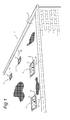
- roof 1 may be at a slight angle. What is important is that such a roof is provided with one or more webs of roof covering 2 which may or may not be fixedly attached to the roof. Instead of fixed attachment means on the roof, it is possible to use ballasting or another way of affixing to ensure the roof covering 2 remains in place, even with wind loads acting on the roof.
- the roof covering is preferably a sheet-type material web. By way of example, a web of bituminous material with fabric is mentioned. Another possibility is a plastic (EPDN) material which may or may not be provided with a (fabric) reinforcement. Such a web of roof covering material makes the roof covering watertight.
- EPDN plastic
- Each safety device consists of a supporting part 4 which is arranged above the roof covering 2 and provided with a tilting eyelet 5 to which a line can be attached by means of which a person situated on the roof can secure themselves.
- a continuous cable may be provided between various safety devices 3, in which case a person situated on the roof can secure themselves to said cable.
- the safety device 3 is installed in such a manner that it can absorb forces in the direction of arrow 16.
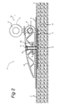
- Fig. 2 shows details of a safety device 3 in the fitted state.
- a base part 7 is situated underneath the roof covering 2 and that this is situated, just like the roof covering 2, on the part 17 of the roof structure situated underneath which is not modified in any way at the location of the base part 7.
- this will be the upper side of a roof structure, such as the top side of an insulating layer or some other boarding.
- Base part 7 is a substantially flat part which is provided with one or more ribs or convex shapes 8 in which nuts or the like may be fitted at predetermined fixed positions. Instead of ribs, it is also possible to use indentations (dimples) or the like. The fastening means can then be arranged in the centre of such indentations.
- the base part 7 may be attached to the structure situated underneath, but it is preferable not to do this.
- a supporting part 4 which is made up of a carrier part 12 which is configured as an elongate wing-shaped profile.
- a sealing covering 6 such as a web of bituminous or adhesive material, is attached which extends beyond the profile on all sides around the profile.
- the profile 12 is provided with openings 19 in which bolts 11 are inserted which are connected to nuts 9.
- one or more recesses 10 are provided at the location of the openings 19 and preferably extend along the entire length of the wing profile 12, which recesses 10 are configured in accordance with rib 8 or slightly larger.
- the base plate 7 When tightening the bolt 11, the base plate 7 will be pulled towards the profile 12 due to the presence of nut 9 and, in the process, accommodate in a clamping manner at least the roof covering 2 and optionally the sealing covering 6 in between if this extends across the entire surface of the profile 12. However, the latter is not imperative. Due to the presence of the rib 8 and the recess 10, the roof covering will be clamped in between very securely in any case. If desired, several bolts 11 are provided in line, as a result of which said clamping force is increased further. It will be understood that the base part may be provided with bolts extending through the roof covering to which the supporting part is attached by means of nuts.
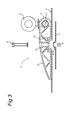
- Fig. 3 shows a detailed view of the various parts which make up the safety device.
- the sealing covering can be sealingly attached to the existing roof covering. This may be effected by means of blowtorching, glueing or the like.
- the roof will be made watertight in a customary way by arranging a web of material across the cut after the base part has been introduced through the cut. Subsequently, the supporting part will be fitted without covering and attached to the roof in the manner described above. Obviously, a combination of both operations is possible, that is to say that the roof is sealed before the supporting part is fitted, and the supporting part is fitted with the covering and further bonding and sealing is carried out, thus providing double protection.
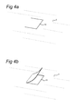
- Fig. 4a shows how a U-shaped cut 15 is made in a roof covering 2.
- Fig. 4b shows the opening of the flap which has been produced in this way.
- Fig. 4c diagrammatically shows how the base part 7 is introduced in the direction of arrow 20.
- the base part 7 can be placed in the space situated underneath the flap, but it is also possible to slide this further to a deeper position underneath the roof covering.
- the base part will preferably be situated completely below the roof covering underneath the cut.
- a part of the base plate 7 to remains extending above the roof covering 2.
- the supporting part 4 can be displaced in the direction of arrow 21 and be placed on to the base part and the roof covering 2 situated.
- the roof covering 2 is drilled through at the location of the opening 19. This can be carried out using an awl, but it is also possible to provide the bolt 11 with a (self-aligning) cutting end at its free end.
- the bolt 11 is introduced further into the opening 19 and positioned opposite nut 9.
- bolt 11 is tightened by means of tool 18 resulting in clamping of the base plate and profile 12.
- a blowtorch 22 can be used to adhere the sealing covering 6 to the existing roof covering 2. Glueing or another attachment means is also possible.
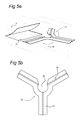
- Fig. 5a and b show a particular embodiment of a part of a safety device according to the invention.
- the base plate assembly 26 consists of a number of base parts 7 shown in the preceding figures.
- the base parts 7 extend across the roof and are in this case arranged at a mutual angle and connected to each other. In the illustrated embodiment, every pair of three base parts 7 is arranged at a mutual angle of 120°.
- An advantage of this embodiment is the fact that the loadability of the safety device is improved and, in addition, is less dependent on the direction of the applied load.
- the base plate assembly 26 is rotated about its central axis 30 and a central opening 29 offers the freedom to slide the base plate assembly 26 underneath the roof covering 2 while the rotation is being carried out.
Landscapes
- Engineering & Computer Science (AREA)
- Architecture (AREA)
- Mechanical Engineering (AREA)
- Civil Engineering (AREA)
- Structural Engineering (AREA)
- Roof Covering Using Slabs Or Stiff Sheets (AREA)
Applications Claiming Priority (1)
| Application Number | Priority Date | Filing Date | Title |
|---|---|---|---|
| NL2006588A NL2006588C2 (nl) | 2011-04-12 | 2011-04-12 | Dak voorzien van veiligheidsinrichting. |
Publications (2)
| Publication Number | Publication Date |
|---|---|
| EP2511448A1 true EP2511448A1 (fr) | 2012-10-17 |
| EP2511448B1 EP2511448B1 (fr) | 2017-03-01 |
Family
ID=45929457
Family Applications (1)
| Application Number | Title | Priority Date | Filing Date |
|---|---|---|---|
| EP12163925.6A Active EP2511448B1 (fr) | 2011-04-12 | 2012-04-12 | Toiture comprenant un système de sécurité et procédé d'installation d'un système de sécurité sur une toiture |
Country Status (3)
| Country | Link |
|---|---|
| EP (1) | EP2511448B1 (fr) |
| DK (1) | DK2511448T3 (fr) |
| NL (1) | NL2006588C2 (fr) |
Cited By (1)
| Publication number | Priority date | Publication date | Assignee | Title |
|---|---|---|---|---|
| GB2511340A (en) * | 2013-02-28 | 2014-09-03 | Latchways Plc | Membrane bonded anchor arrangement |
Citations (5)
| Publication number | Priority date | Publication date | Assignee | Title |
|---|---|---|---|---|
| DE202004018587U1 (de) * | 2004-11-30 | 2005-03-17 | Marzouki Taieb | Vorrichtung zur Sicherung von auf Dächern, insbesondere Flachdächern, tätigen Personen |
| EP1690567A2 (fr) * | 2005-02-15 | 2006-08-16 | Steenmetz Daktechniek B.V. | Ancre de toit |
| EP1698747A2 (fr) | 2005-03-01 | 2006-09-06 | Taieb Marzouki | Dispositif de retenue de personnes occupées sur des toitures, en particulier sur des toitures plates |
| WO2007089139A2 (fr) | 2006-02-03 | 2007-08-09 | Veilig Dak Techniek Bv | Dispositif d'attache, élément de recouvrement et procédé pour empêcher une personne de tomber d'une surface élevée |
| EP2167758A1 (fr) | 2007-08-15 | 2010-03-31 | Safeway Gmbh | Dispositif de sécurité pour toit |
-
2011
- 2011-04-12 NL NL2006588A patent/NL2006588C2/nl not_active IP Right Cessation
-
2012
- 2012-04-12 DK DK12163925.6T patent/DK2511448T3/en active
- 2012-04-12 EP EP12163925.6A patent/EP2511448B1/fr active Active
Patent Citations (5)
| Publication number | Priority date | Publication date | Assignee | Title |
|---|---|---|---|---|
| DE202004018587U1 (de) * | 2004-11-30 | 2005-03-17 | Marzouki Taieb | Vorrichtung zur Sicherung von auf Dächern, insbesondere Flachdächern, tätigen Personen |
| EP1690567A2 (fr) * | 2005-02-15 | 2006-08-16 | Steenmetz Daktechniek B.V. | Ancre de toit |
| EP1698747A2 (fr) | 2005-03-01 | 2006-09-06 | Taieb Marzouki | Dispositif de retenue de personnes occupées sur des toitures, en particulier sur des toitures plates |
| WO2007089139A2 (fr) | 2006-02-03 | 2007-08-09 | Veilig Dak Techniek Bv | Dispositif d'attache, élément de recouvrement et procédé pour empêcher une personne de tomber d'une surface élevée |
| EP2167758A1 (fr) | 2007-08-15 | 2010-03-31 | Safeway Gmbh | Dispositif de sécurité pour toit |
Cited By (2)
| Publication number | Priority date | Publication date | Assignee | Title |
|---|---|---|---|---|
| GB2511340A (en) * | 2013-02-28 | 2014-09-03 | Latchways Plc | Membrane bonded anchor arrangement |
| US10125917B2 (en) | 2013-02-28 | 2018-11-13 | Latchways Plc | Membrane bonded anchor arrangement |
Also Published As
| Publication number | Publication date |
|---|---|
| EP2511448B1 (fr) | 2017-03-01 |
| NL2006588C2 (nl) | 2012-10-15 |
| DK2511448T3 (en) | 2017-05-15 |
Similar Documents
| Publication | Publication Date | Title |
|---|---|---|
| US20100133040A1 (en) | Roof clamp for fall protection safety equipment | |
| US8256183B2 (en) | Safety feature for a roof | |
| US6536729B1 (en) | Bracket assembly including a reservoir | |
| EP2284454A1 (fr) | Système d'assemblage pour panneaux solaires, élément de support pour celui-ci et procédés associés | |
| AU2014268101B2 (en) | Attachment element | |
| US20170338768A1 (en) | Clamps for installation of photovoltaic modules to roofs | |
| CA3049873A1 (fr) | Dispositif pour la protection des personnes contre une chute | |
| EP2511448B1 (fr) | Toiture comprenant un système de sécurité et procédé d'installation d'un système de sécurité sur une toiture | |
| PT1794030E (pt) | Sistema de suporte de tejadilho para um veículo | |
| JP5198812B2 (ja) | 配線・配管材支持具 | |
| JP2013108626A (ja) | 配線・配管材支持具 | |
| CN220173173U (zh) | 一种用于光伏板安装的连接件 | |
| JP2018178599A (ja) | 天井材落下防止構造 | |
| JP2008214980A (ja) | 改修用吊子及びその改修屋根 | |
| JP4944678B2 (ja) | 安全帯等の支持具 | |
| CN206041400U (zh) | 线缆承载装置 | |
| JP6045021B2 (ja) | 屋根上設置物の取付具およびその取付具を用いた屋根上設置物の取付方法 | |
| ITRM20100079A1 (it) | Dispositivo di ancoraggio per sistemi anticaduta particolarmente adatto per coperture metalliche | |
| AU2009100735A4 (en) | Anchor assembly | |
| EP2491201B1 (fr) | Ensemble de verrouillage | |
| EP2561161B1 (fr) | Accessoire pour mise en place d'un système de sécurité | |
| KR20190074142A (ko) | 강관지주 매립장치 | |
| EP4436036A1 (fr) | Support de fixation pour attacher un équipement sur un toit | |
| WO2008094011A1 (fr) | Dispositif de suspension au plafond | |
| US20100213324A1 (en) | Arrangement for installing cables on outer surfaces of crane structures |
Legal Events
| Date | Code | Title | Description |
|---|---|---|---|
| PUAI | Public reference made under article 153(3) epc to a published international application that has entered the european phase |
Free format text: ORIGINAL CODE: 0009012 |
|
| AK | Designated contracting states |
Kind code of ref document: A1 Designated state(s): AL AT BE BG CH CY CZ DE DK EE ES FI FR GB GR HR HU IE IS IT LI LT LU LV MC MK MT NL NO PL PT RO RS SE SI SK SM TR |
|
| AX | Request for extension of the european patent |
Extension state: BA ME |
|
| 17P | Request for examination filed |
Effective date: 20130416 |
|
| 17Q | First examination report despatched |
Effective date: 20150119 |
|
| GRAP | Despatch of communication of intention to grant a patent |
Free format text: ORIGINAL CODE: EPIDOSNIGR1 |
|
| INTG | Intention to grant announced |
Effective date: 20151012 |
|
| GRAP | Despatch of communication of intention to grant a patent |
Free format text: ORIGINAL CODE: EPIDOSNIGR1 |
|
| INTG | Intention to grant announced |
Effective date: 20160323 |
|
| GRAJ | Information related to disapproval of communication of intention to grant by the applicant or resumption of examination proceedings by the epo deleted |
Free format text: ORIGINAL CODE: EPIDOSDIGR1 |
|
| GRAP | Despatch of communication of intention to grant a patent |
Free format text: ORIGINAL CODE: EPIDOSNIGR1 |
|
| INTC | Intention to grant announced (deleted) | ||
| INTG | Intention to grant announced |
Effective date: 20160902 |
|
| GRAS | Grant fee paid |
Free format text: ORIGINAL CODE: EPIDOSNIGR3 |
|
| GRAA | (expected) grant |
Free format text: ORIGINAL CODE: 0009210 |
|
| AK | Designated contracting states |
Kind code of ref document: B1 Designated state(s): AL AT BE BG CH CY CZ DE DK EE ES FI FR GB GR HR HU IE IS IT LI LT LU LV MC MK MT NL NO PL PT RO RS SE SI SK SM TR |
|
| REG | Reference to a national code |
Ref country code: GB Ref legal event code: FG4D |
|
| REG | Reference to a national code |
Ref country code: CH Ref legal event code: EP Ref country code: AT Ref legal event code: REF Ref document number: 871539 Country of ref document: AT Kind code of ref document: T Effective date: 20170315 |
|
| REG | Reference to a national code |
Ref country code: IE Ref legal event code: FG4D |
|
| REG | Reference to a national code |
Ref country code: DE Ref legal event code: R096 Ref document number: 602012029119 Country of ref document: DE |
|
| REG | Reference to a national code |
Ref country code: DK Ref legal event code: T3 Effective date: 20170511 |
|
| REG | Reference to a national code |
Ref country code: NL Ref legal event code: FP |
|
| REG | Reference to a national code |
Ref country code: CH Ref legal event code: NV Representative=s name: FIAMMENGHI-FIAMMENGHI, CH Ref country code: FR Ref legal event code: PLFP Year of fee payment: 6 |
|
| REG | Reference to a national code |
Ref country code: SE Ref legal event code: TRGR |
|
| REG | Reference to a national code |
Ref country code: NO Ref legal event code: T2 Effective date: 20170301 |
|
| REG | Reference to a national code |
Ref country code: LT Ref legal event code: MG4D |
|
| PG25 | Lapsed in a contracting state [announced via postgrant information from national office to epo] |
Ref country code: HR Free format text: LAPSE BECAUSE OF FAILURE TO SUBMIT A TRANSLATION OF THE DESCRIPTION OR TO PAY THE FEE WITHIN THE PRESCRIBED TIME-LIMIT Effective date: 20170301 Ref country code: GR Free format text: LAPSE BECAUSE OF FAILURE TO SUBMIT A TRANSLATION OF THE DESCRIPTION OR TO PAY THE FEE WITHIN THE PRESCRIBED TIME-LIMIT Effective date: 20170602 Ref country code: LT Free format text: LAPSE BECAUSE OF FAILURE TO SUBMIT A TRANSLATION OF THE DESCRIPTION OR TO PAY THE FEE WITHIN THE PRESCRIBED TIME-LIMIT Effective date: 20170301 |
|
| PG25 | Lapsed in a contracting state [announced via postgrant information from national office to epo] |
Ref country code: RS Free format text: LAPSE BECAUSE OF FAILURE TO SUBMIT A TRANSLATION OF THE DESCRIPTION OR TO PAY THE FEE WITHIN THE PRESCRIBED TIME-LIMIT Effective date: 20170301 Ref country code: ES Free format text: LAPSE BECAUSE OF FAILURE TO SUBMIT A TRANSLATION OF THE DESCRIPTION OR TO PAY THE FEE WITHIN THE PRESCRIBED TIME-LIMIT Effective date: 20170301 Ref country code: LV Free format text: LAPSE BECAUSE OF FAILURE TO SUBMIT A TRANSLATION OF THE DESCRIPTION OR TO PAY THE FEE WITHIN THE PRESCRIBED TIME-LIMIT Effective date: 20170301 Ref country code: BG Free format text: LAPSE BECAUSE OF FAILURE TO SUBMIT A TRANSLATION OF THE DESCRIPTION OR TO PAY THE FEE WITHIN THE PRESCRIBED TIME-LIMIT Effective date: 20170601 |
|
| PG25 | Lapsed in a contracting state [announced via postgrant information from national office to epo] |
Ref country code: RO Free format text: LAPSE BECAUSE OF FAILURE TO SUBMIT A TRANSLATION OF THE DESCRIPTION OR TO PAY THE FEE WITHIN THE PRESCRIBED TIME-LIMIT Effective date: 20170301 Ref country code: CZ Free format text: LAPSE BECAUSE OF FAILURE TO SUBMIT A TRANSLATION OF THE DESCRIPTION OR TO PAY THE FEE WITHIN THE PRESCRIBED TIME-LIMIT Effective date: 20170301 Ref country code: SK Free format text: LAPSE BECAUSE OF FAILURE TO SUBMIT A TRANSLATION OF THE DESCRIPTION OR TO PAY THE FEE WITHIN THE PRESCRIBED TIME-LIMIT Effective date: 20170301 Ref country code: EE Free format text: LAPSE BECAUSE OF FAILURE TO SUBMIT A TRANSLATION OF THE DESCRIPTION OR TO PAY THE FEE WITHIN THE PRESCRIBED TIME-LIMIT Effective date: 20170301 |
|
| PG25 | Lapsed in a contracting state [announced via postgrant information from national office to epo] |
Ref country code: IS Free format text: LAPSE BECAUSE OF FAILURE TO SUBMIT A TRANSLATION OF THE DESCRIPTION OR TO PAY THE FEE WITHIN THE PRESCRIBED TIME-LIMIT Effective date: 20170701 Ref country code: PL Free format text: LAPSE BECAUSE OF FAILURE TO SUBMIT A TRANSLATION OF THE DESCRIPTION OR TO PAY THE FEE WITHIN THE PRESCRIBED TIME-LIMIT Effective date: 20170301 Ref country code: SM Free format text: LAPSE BECAUSE OF FAILURE TO SUBMIT A TRANSLATION OF THE DESCRIPTION OR TO PAY THE FEE WITHIN THE PRESCRIBED TIME-LIMIT Effective date: 20170301 Ref country code: PT Free format text: LAPSE BECAUSE OF FAILURE TO SUBMIT A TRANSLATION OF THE DESCRIPTION OR TO PAY THE FEE WITHIN THE PRESCRIBED TIME-LIMIT Effective date: 20170703 |
|
| REG | Reference to a national code |
Ref country code: DE Ref legal event code: R097 Ref document number: 602012029119 Country of ref document: DE |
|
| PLBE | No opposition filed within time limit |
Free format text: ORIGINAL CODE: 0009261 |
|
| STAA | Information on the status of an ep patent application or granted ep patent |
Free format text: STATUS: NO OPPOSITION FILED WITHIN TIME LIMIT |
|
| PG25 | Lapsed in a contracting state [announced via postgrant information from national office to epo] |
Ref country code: MC Free format text: LAPSE BECAUSE OF FAILURE TO SUBMIT A TRANSLATION OF THE DESCRIPTION OR TO PAY THE FEE WITHIN THE PRESCRIBED TIME-LIMIT Effective date: 20170301 |
|
| 26N | No opposition filed |
Effective date: 20171204 |
|
| PG25 | Lapsed in a contracting state [announced via postgrant information from national office to epo] |
Ref country code: SI Free format text: LAPSE BECAUSE OF FAILURE TO SUBMIT A TRANSLATION OF THE DESCRIPTION OR TO PAY THE FEE WITHIN THE PRESCRIBED TIME-LIMIT Effective date: 20170301 |
|
| REG | Reference to a national code |
Ref country code: FR Ref legal event code: PLFP Year of fee payment: 7 |
|
| PGFP | Annual fee paid to national office [announced via postgrant information from national office to epo] |
Ref country code: LU Payment date: 20180427 Year of fee payment: 7 |
|
| PGFP | Annual fee paid to national office [announced via postgrant information from national office to epo] |
Ref country code: IE Payment date: 20180427 Year of fee payment: 7 Ref country code: FI Payment date: 20180430 Year of fee payment: 7 |
|
| PGFP | Annual fee paid to national office [announced via postgrant information from national office to epo] |
Ref country code: IT Payment date: 20180619 Year of fee payment: 7 Ref country code: FR Payment date: 20180427 Year of fee payment: 7 |
|
| PG25 | Lapsed in a contracting state [announced via postgrant information from national office to epo] |
Ref country code: MT Free format text: LAPSE BECAUSE OF NON-PAYMENT OF DUE FEES Effective date: 20170412 |
|
| PG25 | Lapsed in a contracting state [announced via postgrant information from national office to epo] |
Ref country code: HU Free format text: LAPSE BECAUSE OF FAILURE TO SUBMIT A TRANSLATION OF THE DESCRIPTION OR TO PAY THE FEE WITHIN THE PRESCRIBED TIME-LIMIT; INVALID AB INITIO Effective date: 20120412 |
|
| REG | Reference to a national code |
Ref country code: AT Ref legal event code: UEP Ref document number: 871539 Country of ref document: AT Kind code of ref document: T Effective date: 20170301 |
|
| PG25 | Lapsed in a contracting state [announced via postgrant information from national office to epo] |
Ref country code: CY Free format text: LAPSE BECAUSE OF NON-PAYMENT OF DUE FEES Effective date: 20170301 |
|
| PG25 | Lapsed in a contracting state [announced via postgrant information from national office to epo] |
Ref country code: MK Free format text: LAPSE BECAUSE OF FAILURE TO SUBMIT A TRANSLATION OF THE DESCRIPTION OR TO PAY THE FEE WITHIN THE PRESCRIBED TIME-LIMIT Effective date: 20170301 |
|
| PG25 | Lapsed in a contracting state [announced via postgrant information from national office to epo] |
Ref country code: LU Free format text: LAPSE BECAUSE OF NON-PAYMENT OF DUE FEES Effective date: 20190412 |
|
| PG25 | Lapsed in a contracting state [announced via postgrant information from national office to epo] |
Ref country code: FI Free format text: LAPSE BECAUSE OF NON-PAYMENT OF DUE FEES Effective date: 20190412 |
|
| PG25 | Lapsed in a contracting state [announced via postgrant information from national office to epo] |
Ref country code: FR Free format text: LAPSE BECAUSE OF NON-PAYMENT OF DUE FEES Effective date: 20190430 |
|
| PG25 | Lapsed in a contracting state [announced via postgrant information from national office to epo] |
Ref country code: TR Free format text: LAPSE BECAUSE OF FAILURE TO SUBMIT A TRANSLATION OF THE DESCRIPTION OR TO PAY THE FEE WITHIN THE PRESCRIBED TIME-LIMIT Effective date: 20170301 |
|
| PG25 | Lapsed in a contracting state [announced via postgrant information from national office to epo] |
Ref country code: IE Free format text: LAPSE BECAUSE OF NON-PAYMENT OF DUE FEES Effective date: 20190412 Ref country code: IT Free format text: LAPSE BECAUSE OF NON-PAYMENT OF DUE FEES Effective date: 20190412 |
|
| PG25 | Lapsed in a contracting state [announced via postgrant information from national office to epo] |
Ref country code: AL Free format text: LAPSE BECAUSE OF FAILURE TO SUBMIT A TRANSLATION OF THE DESCRIPTION OR TO PAY THE FEE WITHIN THE PRESCRIBED TIME-LIMIT Effective date: 20170301 |
|
| REG | Reference to a national code |
Ref country code: DE Ref legal event code: R082 Ref document number: 602012029119 Country of ref document: DE Representative=s name: KILBURN & STRODE LLP, NL |
|
| PGFP | Annual fee paid to national office [announced via postgrant information from national office to epo] |
Ref country code: DE Payment date: 20210428 Year of fee payment: 10 Ref country code: NO Payment date: 20210430 Year of fee payment: 10 |
|
| PGFP | Annual fee paid to national office [announced via postgrant information from national office to epo] |
Ref country code: DK Payment date: 20210428 Year of fee payment: 10 Ref country code: CH Payment date: 20210428 Year of fee payment: 10 Ref country code: AT Payment date: 20210428 Year of fee payment: 10 Ref country code: SE Payment date: 20210428 Year of fee payment: 10 |
|
| PGFP | Annual fee paid to national office [announced via postgrant information from national office to epo] |
Ref country code: BE Payment date: 20220427 Year of fee payment: 11 |
|
| REG | Reference to a national code |
Ref country code: DE Ref legal event code: R119 Ref document number: 602012029119 Country of ref document: DE |
|
| REG | Reference to a national code |
Ref country code: DK Ref legal event code: EBP Effective date: 20220430 |
|
| REG | Reference to a national code |
Ref country code: NO Ref legal event code: MMEP |
|
| REG | Reference to a national code |
Ref country code: SE Ref legal event code: EUG |
|
| REG | Reference to a national code |
Ref country code: CH Ref legal event code: PL |
|
| REG | Reference to a national code |
Ref country code: AT Ref legal event code: MM01 Ref document number: 871539 Country of ref document: AT Kind code of ref document: T Effective date: 20220412 |
|
| PG25 | Lapsed in a contracting state [announced via postgrant information from national office to epo] |
Ref country code: SE Free format text: LAPSE BECAUSE OF NON-PAYMENT OF DUE FEES Effective date: 20220413 Ref country code: NO Free format text: LAPSE BECAUSE OF NON-PAYMENT OF DUE FEES Effective date: 20220430 Ref country code: LI Free format text: LAPSE BECAUSE OF NON-PAYMENT OF DUE FEES Effective date: 20220430 Ref country code: DE Free format text: LAPSE BECAUSE OF NON-PAYMENT OF DUE FEES Effective date: 20221103 Ref country code: CH Free format text: LAPSE BECAUSE OF NON-PAYMENT OF DUE FEES Effective date: 20220430 Ref country code: AT Free format text: LAPSE BECAUSE OF NON-PAYMENT OF DUE FEES Effective date: 20220412 |
|
| PG25 | Lapsed in a contracting state [announced via postgrant information from national office to epo] |
Ref country code: DK Free format text: LAPSE BECAUSE OF NON-PAYMENT OF DUE FEES Effective date: 20220430 |
|
| REG | Reference to a national code |
Ref country code: BE Ref legal event code: MM Effective date: 20230430 |
|
| PG25 | Lapsed in a contracting state [announced via postgrant information from national office to epo] |
Ref country code: BE Free format text: LAPSE BECAUSE OF NON-PAYMENT OF DUE FEES Effective date: 20230430 |
|
| PGFP | Annual fee paid to national office [announced via postgrant information from national office to epo] |
Ref country code: NL Payment date: 20250509 Year of fee payment: 14 |
|
| PGFP | Annual fee paid to national office [announced via postgrant information from national office to epo] |
Ref country code: GB Payment date: 20250520 Year of fee payment: 14 |