EP2511583A2 - Structure de raccord, raccord de tuyau et tête de disposition de tuyau - Google Patents
Structure de raccord, raccord de tuyau et tête de disposition de tuyau Download PDFInfo
- Publication number
- EP2511583A2 EP2511583A2 EP12164040A EP12164040A EP2511583A2 EP 2511583 A2 EP2511583 A2 EP 2511583A2 EP 12164040 A EP12164040 A EP 12164040A EP 12164040 A EP12164040 A EP 12164040A EP 2511583 A2 EP2511583 A2 EP 2511583A2
- Authority
- EP
- European Patent Office
- Prior art keywords
- tube
- pipe
- connection
- notch
- pipe fitting
- Prior art date
- Legal status (The legal status is an assumption and is not a legal conclusion. Google has not performed a legal analysis and makes no representation as to the accuracy of the status listed.)
- Granted
Links
Images


Classifications
-
- F—MECHANICAL ENGINEERING; LIGHTING; HEATING; WEAPONS; BLASTING
- F16—ENGINEERING ELEMENTS AND UNITS; GENERAL MEASURES FOR PRODUCING AND MAINTAINING EFFECTIVE FUNCTIONING OF MACHINES OR INSTALLATIONS; THERMAL INSULATION IN GENERAL
- F16L—PIPES; JOINTS OR FITTINGS FOR PIPES; SUPPORTS FOR PIPES, CABLES OR PROTECTIVE TUBING; MEANS FOR THERMAL INSULATION IN GENERAL
- F16L37/00—Couplings of the quick-acting type
- F16L37/08—Couplings of the quick-acting type in which the connection between abutting or axially overlapping ends is maintained by locking members
- F16L37/084—Couplings of the quick-acting type in which the connection between abutting or axially overlapping ends is maintained by locking members combined with automatic locking
- F16L37/091—Couplings of the quick-acting type in which the connection between abutting or axially overlapping ends is maintained by locking members combined with automatic locking by means of a ring provided with teeth or fingers
-
- F—MECHANICAL ENGINEERING; LIGHTING; HEATING; WEAPONS; BLASTING
- F16—ENGINEERING ELEMENTS AND UNITS; GENERAL MEASURES FOR PRODUCING AND MAINTAINING EFFECTIVE FUNCTIONING OF MACHINES OR INSTALLATIONS; THERMAL INSULATION IN GENERAL
- F16L—PIPES; JOINTS OR FITTINGS FOR PIPES; SUPPORTS FOR PIPES, CABLES OR PROTECTIVE TUBING; MEANS FOR THERMAL INSULATION IN GENERAL
- F16L41/00—Branching pipes; Joining pipes to walls
- F16L41/02—Branch units, e.g. made in one piece, welded, riveted
- F16L41/03—Branch units, e.g. made in one piece, welded, riveted comprising junction pieces for four or more pipe members
Definitions
- the present invention relates to a pipe layout header that branches in-flowing fluid, a pipe fitting for configuring a pipe layout header by connecting together plural pipe fittings, and a fitting structure for configuring a pipe fitting.
- Pipe layout headers are recently being employed configured by connecting together plural pipe fittings having straight flow paths and branch flow paths branching off from the straight flow paths.
- the header structure of Japanese Patent Application Laid-Open (JP-A) No. 2007-100807 is configured by connecting together plural header units wherein an inner tube formed to an end portion of a header unit is inserted into a tube body formed at an end portion of another header unit using one-touch connection.
- the configuration of the header structure cannot be changed once it has been assembled.
- a new header unit has to be manufactured at the factory as it is not possible to for example remove or change the order of header units on-site.
- an object of the present invention is to provide a pipe fitting which is capable of connection and connection release, and a pipe layout header configured from such pipe fittings.
- a first aspect of the invention is a pipe fitting including an inner pipe section with a connection portion formed at a first end portion and an outer pipe section provided at the outer periphery of the inner pipe section such that a second end portion of the inner pipe section is exposed, wherein: the connection portion includes a retaining member for retaining the second end portion of the inner pipe section of a first of the pipe fittings that has been inserted into the connection portion, and a releasing member for releasing the retained state due to the retaining member; and a space formed in a retained state when the second end portion of the inner pipe section has been inserted into the connection portion of a second of the pipe fittings and the second pipe fitting is retained by the retaining member, the space being formed between a first end portion of the outer pipe section and the connection portion of the second pipe fitting and the space enabling operation of the releasing member.
- the first pipe fitting and the second pipe fitting can be connected together by inserting the second end portion of the inner pipe section into the connection portion of the second pipe fitting so as to be retained by the retaining member of the second pipe fitting.
- the retained state of the second end portion of the inner pipe section due to the retaining member of the second pipe fitting is released by utilizing the space formed between the first end portion of the outer pipe section and the connection portion of the second pipe fitting to operate the releasing member. Connection between the first pipe fitting and the second pipe fitting can accordingly be released.
- a second aspect of the invention is the pipe fitting of the first aspect wherein the space is configured by a notch where the first end portion of the outer pipe section is notched.
- various sizes, placements and numbers of spaces can be formed at the first end portion of the outer pipe section due to configuring the space by a notch.
- plural of the notches are formed around the circumferential direction at the first end portion of the outer pipe section.
- connection of the pipe fittings cannot be released unless plural notches are utilized at the same time. Namely, connection of the pipe fittings can be prevented from being released unintentionally. Release of the connection of the pipe fittings can also be restricted to designated personnel competent to release pipe fitting connections (to personnel capable of reliably connecting the pipe fittings). Mistakes in connecting the pipe fittings can be prevented by adopting such an approach since only such personnel (designated personnel) then perform connection operations on the pipe fittings.
- a fourth aspect of the invention includes a branch flow path branching off from the inner pipe section.
- fluid flowing into the pipe fittings can be branched.
- a fifth aspect of the invention is a pipe layout header configured by plural pipe fittings of any one of the first aspect to the fourth aspect connected together.
- pipe layout headers can be configured from various combinations of the pipe fittings.
- a fitting structure includes: a first tube body configured with a multilayer construction including an inner tube formed with an internal first flow path and an outer tube surrounding the inner tube, and including a connection tube portion for use in connection provided at a first end portion of the first tube body where the outer tube is removed from the inner tube; a second tube body equipped with an internal second flow path, and provided with connection means connected to the connection tube portion that has been inserted into an end portion in order to communicate the first flow path and the second flow path; a notch formed where the outer tube facing the second tube body has been removed, and into which a tool is inserted and moved along the inner tube so as to release connection to the connection means; and restriction means that projects out from the outer tube towards the notch, is capable of being removed, and prevents the tool from being inserted.
- the first tube body and the second tube body are connected by the connection means, and the first flow path and the second flow path and in communication with each other.
- the multilayer construction first tube body is notched on the outer tube facing the second tube body, forming a notch of a size to insert a pressing member.
- a restriction means is provided to the notch to prevent the insertion of the pressing member.
- the connected first tube body and second tube body can be separated by the following procedure. Namely, first the restriction means that is provided to the notch on the first tube member is removed and the pressing member is inserted into the notch. The pressing member is then moved along the axial direction of the inner tube. The connection of the connection means of the second tube body is accordingly released, and the first tube body and the second tube body can be separated.
- a seventh aspect of the invention is the fitting structure of the sixth aspect wherein the restriction means projects out from an end face of the notch along the first tube body axial line direction.
- the restriction means projects out from the end face of the notch on the outer tube along the first tube body axial line direction, preventing the pressing member from being inserted into the notch. It is accordingly not possible to insert the pressing member into the notch without removing the restriction means. As a result, a state in which the restriction means has been removed can serve as evidence that the first tube body and the second tube body have been separated.
- An eighth aspect of the invention is the fitting structure of the sixth aspect wherein the restriction means projects out from an end face of the notch along the first tube body circumferential direction.
- the restriction means projects out from an end face of the notch on the outer pipe section along the first tube body circumferential direction, preventing the pressing member from being inserted into the notch. It is accordingly not possible to insert the pressing member into the notch without removing the restriction means. As a result, a state in which the restriction means has been removed can serve as evidence that the first tube body and the second tube body have been separated.
- a ninth aspect of the invention is the fitting structure of the sixth aspect wherein: the notch is formed by removing the outer tube from both sides along a tangent to the inner tube as far as the outer peripheral face of the inner tube; and the restriction means projects out at respective end faces of the notch along the first tube body axial line direction.
- the restriction means is provided projecting out of end faces on both sides of the notch on the outer tube along the first tube body axial direction, preventing the pressing member from being inserted into the notch. It is accordingly not possible to insert the pressing member into the notch without removing the restriction means. As a result, a state in which the restriction means has been removed can serve as evidence that the first tube body and the second tube body have been separated.
- a pipe fitting includes: a tube body of multi-layer construction including an inner tube formed with an internal flow path and an outer tube surrounding the inner tube, first connection means provided at a first end portion of the tube body for connecting a first connection tube portion that has been inserted from outside, and a second connection tube portion for connection provided at a second end portion of the tube body where the outer tube is removed from the inner tube, and a branch tube body projecting out in a radial direction from a peripheral wall of the inner tube and equipped with a branch flow path in communication with the flow path; a notch formed by removing the outer tube on the second end side such that when the second connection tube portion has been connected to an external second connection means a tool is inserted and moved along the inner tube for releasing connection to the second connection means; and restriction means that projects from the outer tube towards the notch and is capable of being removed, and prevents insertion of the tool.
- the pipe fittings are connected by the first connection tube portion that has been inserted from outside by the first connection means provided to the first end portion, putting the flow path of the first connection tube portion and the flow path of the pipe fitting in communication with each other.
- the second connection tube portion formed at the second end portion is connected to the external second connection means, putting the flow paths of the pipe fittings and the flow path of the second connection means in communication with each other.
- a notch is formed by removing the outer tube.
- the restriction means that prevents the insertion of a pressing member for releasing the connection to the second connection means is provided to the notch.
- the second connection means and the second connection tube portion can be separated after the second connection tube portion and the external second connection means have been connected to configure the pipe layout header.
- An operation to remove the restriction means provided to the notch is necessary in order to perform separation, and a state in which the restriction means has been removed from the outer tube can serve as evidence that the second connection means and the second connection tube portion have been separated. In other words, separation can be verified.
- the restriction means is greatly deformed even though the restriction means has not actually been removed, since signs of plastic deformation in the joining portion of the restriction means to the outer tube remain, this can still serve as evidence that the first tube body and the second tube body have been separated in such cases too.
- An eleventh aspect of the invention is the pipe fitting of the tenth aspect wherein the restriction means projects out from an end face of the notch along an axial line direction of the tube body.
- the restriction means projects out from the end face of the notch on the outer tube along the axial line direction of the tube body, preventing insertion of the pressing member into the notch. It is accordingly not possible to insert the pressing member into the notch without removing the restriction means. As a result, a state in which the restriction means has been removed can serve as evidence that the second connection means and the second connection tube portion have been separated.
- a twelfth aspect of the invention is the pipe fitting of the tenth aspect wherein the restriction means projects out from an end face of the notch along the circumferential direction of the tube body.
- the restriction means projects out from an end face of the notch on the outer tube along the circumferential direction of the tube body, preventing the insertion of the pressing member into the notch. It is accordingly not possible to insert the pressing member into the notch without removing the restriction means. As a result, a state in which the restriction means has been removed can serve as evidence that the second connection means and the second connection tube portion have been separated.
- a thirteenth aspect of the invention is the pipe fitting of the tenth aspect wherein: the notch is formed by removing the outer tube from both sides along a tangent to the inner tube as far as the outer peripheral face of the inner tube; and the restriction means projects out at respective end faces of the notch along the axial line direction of the tube body.
- the restriction means projects out at end faces of the notch from both sides of the outer tube along the axial line direction of the tube body, preventing the insertion of the pressing member into the notch. It is accordingly not possible to insert the pressing member into the notch without removing the restriction means. As a result, a state in which the restriction means has been removed can serve as evidence that the second connection means and the second connection tube portion have been separated.
- a pipe layout header includes: a first pipe fitting of multi-layer construction including an inner tube formed with an internal first flow path and an outer tube surrounding the inner tube, first connection means provided at a first end portion of the first pipe fitting for connecting a first connection tube portion that has been inserted from outside, and a second connection tube portion provided at a second end portion of the first pipe fitting where the outer tube is removed, and a branch tube body projecting out in a radial direction from a peripheral wall of the inner tube and equipped with a branch flow path in communication with the first flow path; a second pipe fitting of multi-layer construction including an inner tube formed with an internal second flow path and an outer tube surrounding the inner tube, second connection means provided at a first end portion of the second pipe fitting and connected to the second connection tube portion, a third connection tube portion formed at a second end portion of the second pipe fitting where the outer tube is removed, and a branch tube body projecting out in a radial direction from a peripheral wall of the inner tube and equipped with a branch flow
- the first pipe fitting and the second pipe fitting are attached by the second connection means, putting the first flow path and the second flow path in communication with each other.
- the multi-layer construction first pipe fitting is formed with a notch formed by removing the outer tube and into which a pressing member is inserted.
- the notch is provided with the restriction means to prevent the insertion of the pressing member.
- the connected first pipe fitting and second pipe fitting can be separated by the following procedure. Namely, first the restriction means that is provided to the notch on the first pipe fitting is removed and a tool is inserted into the notch. The tool is then moved along the axial direction of the inner tube of the first pipe fitting. The connection of the connection means of the second header unit is accordingly released, and the first pipe fitting and the second pipe fitting can be separated.
- a fifteenth aspect of the invention is the pipe layout header of the fourteenth aspect wherein the restriction means projects out from an end face of the notch along the axial line direction of the first pipe fitting.
- the restriction means projects out from an end face of the notch on the outer tube along the axial line direction of the tube body, preventing the insertion of the pressing member into the notch. It is accordingly not possible to insert the pressing member into the notch without removing the restriction means. As a result, a state in which the restriction means has been removed can serve as evidence that the first pipe fitting and the second pipe fitting have been separated.
- a sixteenth aspect of the invention is the pipe layout header of the fourteenth aspect wherein the restriction means projects out from an end face of the notch along the circumferential direction of the first pipe fitting.
- the restriction means is provided to an end face of the notch on the outer tube along the circumferential direction of the tube body, preventing the insertion of the pressing member into the notch. It is accordingly not possible to insert the pressing member into the notch without removing the restriction means. As a result, a state in which the restriction means has been removed can serve as evidence that the first pipe fitting and the second pipe fitting have been separated.
- a seventeenth aspect of the invention is the pipe layout header of the fourteenth aspect wherein: the notch is formed by removing the outer tube from both sides along a tangent to the inner tube as far as the outer peripheral face of the inner tube; and the restriction means projects out at the two end faces of the notch along the axial line direction of the first pipe fitting.
- the restriction means projects out at the end faces on both sides of the notch of the outer tube along the axial line direction of the tube body, preventing insertion of the pressing member into the notch. It is accordingly not possible to insert the pressing member into the notch without removing the restriction means. As a result, a state in which the restriction means has been removed can serve as evidence that the first pipe fitting and the second pipe fitting have been separated.
- the present invention can provide a pipe fitting which is capable of connection and connection release, and a pipe layout header configured from these pipe fittings.
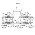
- a pipe layout header 10 is configured from plural connected header units 12 serving as pipe fittings.
- each of the header units 12 includes an inner pipe 14 serving as an inner pipe section, an outer covering resin 24 serving as an outer pipe section, a connection portion 18, and a branch opening 20.
- header unit 12A serving as a first pipe fitting
- header unit 12B serving as a header unit 12B
- header unit 12C serving as the second pipe fitting
- the inner pipe 14 includes a straight flow path 22 along which a fluid such as cold or hot water flows.
- a branch flow path (not shown in the drawings) is provided in the inner pipe 14 branching off from the straight flow path 22 substantially orthogonal to the straight flow path 22.
- a pipe body such as a hot or cold water supply pipe or waste water pipe is detachably connected to the branch opening 20 configuring the outlet-inlet for fluid to flow in the branch flow path.
- connection portion 18 is configured including a tube portion 92 formed to a portion at one end of the inner pipe 14, and a cap 38 provided on the tube portion 92. Namely, the connection portion 18 is formed at a first end portion of the inner pipe 14. A second end portion 16 of the inner pipe 14 is exposed at the outer face (outer periphery) of the central portion of the inner pipe 14 (in the vicinity of the intersection between the straight flow path 22 and the branch flow path) and covered by the outer covering resin 24.
- a male thread 36 is formed to the outer peripheral face of the tube portion 92 and the cap 38 formed in a circular cylindrical shape is attached to the tube portion 92 by screwing the male thread 3 6 into a female thread 40 formed to the inner peripheral face of the cap 38.
- An O-ring 30, a support ring 32 and a collet 34 serving as a releasing member are provided along the inner wall of the tube portion 92, in sequence from an opening 26 formed to the second end portion 16 of the inner pipe 14 towards an opening 28 of the cap 38.
- direction X the direction from the opening 26 towards the opening 28 with respect to the component axis of the inner pipe 14
- direction Y the direction from the opening 28 towards the opening 26
- the O-ring 30, the support ring 32 and the collet 34 are ring shaped members.
- the O-ring 30 makes contact with the outer peripheral face of the inner pipe 14 when the second end portion 16 of the inner pipe 14 of a first of the header units 12 has been inserted into the tube portion 92, thereby securing a watertight connection portion between the inner pipe 14 and the connection portion 18 (such that fluid does not flow out from the connection portion of the inner pipe 14 and the connection portion 18).
- a flange portion 42 is formed at an end portion on the opening 28 side of the support ring 32, projecting out towards the radial direction outside of the support ring 32.
- a flange portion 44 is formed at an end portion on the O-ring 30 side of the support ring 32, projecting out towards the radial direction inside of the support ring 32.
- the support ring 32 is fixed to the tube portion 92 such that the flange portion 42 of the support ring 32 is sandwiched between an end portion of the tube portion 92 and the cap 3 8 attached to the tube portion 92.
- the flange portion 44 is disposed between the O-ring 30 and the collet 34, and the leading end portion of the flange portion 44 is formed in a wedge shape with a taper portion 46 that slopes towards the support ring 32 radial direction inside on progression in direction X.
- the collet 34 is provided so as to be moveable in the X direction and the Y direction, and the collet 34 can be expanded or contracted in the collet 34 radial direction due to plural slits (not shown in the drawings) being formed in the collet 34 along the member axial direction.
- Plural claw members 48 serving as retaining members are provided to the collet 34 around the circumferential direction, projecting out from the inner peripheral face of the collet 34 towards the radial direction inside.
- the claw members 48 project out towards the collet 34 radial direction inside on progression in the Y direction. Namely the claw members 48 are provided as retaining members to the inner wall of the tube portion 92.
- a tapered portion 50 is formed in the vicinity of an X direction intermediate portion of the outer peripheral face of the collet 34, such that the outer diameter of the collet 34 decreases on progression in the X direction.
- a tapered portion 52 facing the tapered portion 50 is formed on the inner peripheral face of the cap 38.
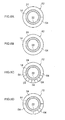
- a single notch 54 is formed where a portion of the outer covering resin 24 is notched. As shown in Fig. 8A illustrating the cross-section taken on A-A of Fig. 2 , the notch 54 is formed in a semi-circular arc shape where the bottom half of the outer covering resin 24 has been notched. A pressing member 56, described later, is inserted into the notch 54.
- connection and connection release of the header units of an exemplary embodiment of the present invention The following explanation describes connection and connection release for the header unit 12B and the header unit 12C, however connection and connection release is similar for other header units.
- the inner pipe 14 moves in the X direction when fluid flowing in the inner pipe 14 (the straight flow path 22) presses the inside of the inner pipe 14 (the straight flow path 22) or when force attempting to pull the inner pipe 14 out from the connection portion 18 acts, such as when the header unit 12B is tugged.
- the end portion of the collet 34 accordingly slides down over the taper portion 46 of the support ring 32, decreasing the diameter of the collet 34 in the radial direction.
- the force pressing the claw members 48 against the outer peripheral face of the inner pipe 14 accordingly increases.
- the second end portion 16 of the inner pipe 14 can thereby be prevented from coming out from the connection portion 18 and the second end portion 16 of the inner pipe 14 can be retained in the connection portion 18.
- the collet 34 moves further in the X direction, and the tapered portion 50 of the collet 34 slides against the tapered portion 52 of the cap 38.
- the diameter of the collet 34 in the radial direction thereby decreases, and the force pressing the claw members 48 against the outer peripheral face of the inner pipe 14 increases, such that the claw members 48 dig into the outer peripheral face of the second end portion 16.
- the second end portion 16 of the inner pipe 14 can thereby be prevented from coming out from the connection portion 18 and the second end portion 16 of the inner pipe 14 can be retained in the connection portion 18
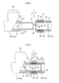
- the pressing member 56 is inserted into the notch 54.
- the pressing member 56 is thereby disposed in front of the collet 34 as shown in the longitudinal cross-section of Fig. 6B .
- the pressing member 56 is configured by a semicircular shaped circular arc cross-sectioned plate portion 58 and a flange portion 60 provided protruding out towards the radial direction outside from an end portion of the plate portion 58.
- the pressing member 56 is pressed in along the Y direction such that the end face of the plate portion 58 contacts the end face of the collet 34, and presses the collet 34 in (in the Y direction) towards the far side of the tube portion 92. Due to the collet 34 thereby moving in the Y direction the end portion of the collet 34 slides up over the taper portion 46 of the support ring 32, and so the diameter of the collet 34 increases in the radial direction.
- the notch 54 is provided between a first end portion of the outer covering resin 24 of the header unit 12B and the connection portion 18 of the header unit 12C (the cap 38) as a space in which the collet 34 can be operated.
- the header unit 12B and the header unit 12C can be connected together by inserting the second end portion 16 of the inner pipe 14 of the header unit 12B into the connection portion 18 of the header unit 12C so as to be retained by the claw members 48 of the header unit 12C.
- the state in which the claw members 48 prevent the second end portion 16 of the inner pipe 14 inserted into the connection portion 18 from coming out is released by inserting the pressing member 56 into the notch 54, disposing the pressing member 56 in front of the collet 34, and using the pressing member 56 to press the collet 34 in (in the Y direction) towards the far side of the tube portion 92.
- the connection between the header unit 12B and the header unit 12C can accordingly be released. Namely, the retained state of the second end portion 16 of the inner pipe 14 due to the claw members 48 of the header unit 12C is released by utilizing the space of the notch 54 to operate the collet 34. Connection between the header unit 12B and the header unit 12C can accordingly be released.
- connection of the header units 12 and connection release of the header units 12 is thus enabled, when a need has arisen to change the configuration of the header structure of the pipe layout header 10 on the site installed with the pipe layout header 10, the number of header units 12 can be increased or decreased, and the sequence of the header units 12 can be changed. A reduction can accordingly be achieved in waste of header units 12 discarded due to becoming unusable due to changing the configuration of a header structure of the pipe layout header 10. An operator can accordingly perform connection operations of the header units 12 on site without the concern of connecting the header units 12 in the wrong configuration.
- notch 54 As a space in which the collet 34 serving as the release member can be operated, various sizes, placements and numbers of spaces can be configured at the first end portion of the outer covering resin 24.
- Fluid flowing into the header units 12 can be branched due to the branch flow path branching from the inner pipe 14.
- Pipe layout headers 10 can also be configured from various combinations of the header units 12 by performing plural connections of header units 12.
- the notch 54 may be formed in any shape as long as a pressing member can be inserted and disposed in front of the collet 34, and the collet 34 can be pushed by the pressing member towards the far side of the connection portion 18.
- Plural notches 54 may also be formed around the circumferential direction of the outer covering resin 24. Configuration may be made with the notch 54 formed in a face-on view (cross-section taken on A-A of Fig. 2 ) circular shape around the entire circumference of the first end portion of the outer covering resin 24, as shown in the transverse cross-section of Fig.
- FIG. 8B or with plural of the notches 54 formed along the circumferential direction of the first end portion of the outer covering resin 24, as shown in the transverse cross-sections of Fig. 8C and Fig. 8D .
- a pressing member 56 as illustrated in the perspective view of Fig. 9A may be employed in the case of the notches 54 illustrated in Fig. 8C .
- a pressing member 56 as illustrated in the perspective view of Fig. 9B may be employed in the case of the notches 54 illustrated in Fig. 8D .
- connection of the header units 12 cannot be released unless a pressing member 56 is employed capable of being inserted into plural notches 54 at the same time and pressing the collet 34 (unless plural notches 54 are utilized at the same time)" can be achieved by forming plural of the notches 54 along the circumferential direction at the first end portion of the outer covering resin 24.
- connection of the header units 12 can be prevented from being released unintentionally.
- Release of the connection of the header units 12 can also be restricted to designated personnel competent to release connections (to personnel capable of reliably connecting header units 12). Mistakes in connecting the header units 12 can be prevented by adopting such an approach since only such personnel (designated personnel) perform connection operations on the header units 12.
- release of the connection of the header units 12 can also be restricted to designated personnel competent to release connections of the header units 12 by blocking the notch 54 with a cover that cannot be removed without using a particular implement such as a pressing member.
- the outer face of the inner pipe 14 serving as the inner pipe section is covered by the outer covering resin 24 serving as the outer pipe section.
- configuration may be made with a single component (referred to below as "fitting body") in which the outer covering resin 24 and the inner pipe 14 are integrated together such as by integral molding.
- the fitting body has an inner pipe section configured similarly to the inner pipe 14 and an outer pipe section configured similarly to the outer covering resin 24. Namely portions on the inside of the single component fitting body serve as the inner pipe section, and portions on the outside as the outer pipe section.
- the notch 54 is formed by a notch in the outer covering resin 24.
- the length of the member axial direction of the second end portion 16 of the inner pipe 14 can be made longer such that, in a state in which the second end portion 16 of the inner pipe 14 of the header unit 12B is completely inserted into the connection portion 18 of the header unit 12C, a space is provided into which the pressing member 56 can be inserted and disposed in front of the collet 34 (the space 94 in which the collet 34 can be operated).
- the exemplary embodiment of the present invention is applicable to any header unit including: a retaining member for preventing an end portion of an inner pipe section of one header unit that has been inserted into a connection portion of another header unit from coming out; and a releasing member for releasing a retaining member retained state of the inner pipe section by pressing the retaining member towards the far side connection portion.
- a notch 64 may be provided in header units 62A, 62B of the configuration illustrated in the longitudinal cross-section of Fig. 11 .
- a tube portion 68 of a header unit 62A is inserted into an internal pipe 66 of the header unit 62B serving as an inner pipe section, and the internal pipe 66 is covered in this state by a cover 88 serving as a connection portion.
- a claw member 70 serving as a retaining member is provided at the inside of a cap 90 fixed to the cover 88, thereby preventing the internal pipe 66 from coming out of the cover 88.
- a release ring 72 serving as a releasing member is provided at the inside of the cap 90. The release ring 72 is pushed towards the far side of the cover 88 by a pressing member (not shown in the drawings), releasing the retained state in which the claw member 70 prevents the internal pipe 66 from coming out from the cover 88.
- Configuration may also be made such that, as illustrated in the perspective view of Fig. 12A , claw members 76 are provided as retaining members to a circular cylindrical shaped collet 74, and a circular cylindrical shaped release ring 78 is provided as a releasing member, as shown in Fig. 12B .
- the collet 74, the claw members 76 and the release ring 78 are provided at the inner wall of a connection portion configuring a header unit.
- the claw member 76 is provided so as to project out from the inner peripheral face of the collet 74.
- the collet 74 is formed with slits 82 that have tapered portions 80 formed along the member axial direction on the inner wall face of the collet 74.
- Projection members 86 that have tapered portions 84 are also provided so as to project out on the outer wall face of the release ring 78, downwards in Fig. 12A .
- the release ring 78 and the collet 74 are provided at the inner wall of the connection portion configuring the header unit in a state in which the projection members 86 are inserted into the slits 82. Accordingly, when the release ring 78 is pressed by the pressing member towards the collet 74 (towards the far side of the connection portion), the tapered portions 84 of the projection members 86 press and slide against the tapered portions 80 of the slits 82, widening the slits 82 in the projection members 86.
- header units 12 of the exemplary embodiment of the present invention may be connected together.
- Plurals header units 12 for connecting together may also be of similar specification as each other, or may be of different specifications from each other, or some of the header units 12 may be of similar specification to each other and others different. Specification here refers to such factors as the length of the straight flow path, whether or not there is a branch flow path, the size of a branch opening (diameter of contactable pipe body), location of the branch opening and/or number branch openings.
- the header units 12 of the exemplary embodiment of the present invention may be employed as pipe fittings for connecting pipe bodies to each other, for example pipes for hot or cold water or waste water.
- the header units 12 of the exemplary embodiments of the present invention can also be applied to various connection structures for connecting together pipe shaped members.
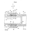
- a fitting structure 110 includes a first pipe 180 and a second pipe 182, with the first pipe 180 and the second pipe 182 connected together with a one-touch fitting (connection portion) 122.
- the first pipe 180 has a double tube construction (multi-layer construction) including an inner tube (inner pipe) 118 formed with an internal first flow path 116, and an outer tube 146 surrounding the inner pipe 118.
- the inner pipe 118 is molded in a heat resistant resin or metal material, and the outer tube (outer covering resin) 146 is formed from a resin material.
- the taper portion 146 performs at least one role out of reinforcing the connection portion 118, protecting the connection portion 118, heat preservation, or improving the visual appearance of the connection portion 118.
- a tube portion 120 is formed to an end portion of the first pipe 180.
- the tube portion 120 is a portion for insertion into the connection portion 122, and is provided over a range of length L1 from the leading end portion of the first pipe 180.
- the outer tube 146 is removed over the range of the tube portion 120.
- An internal second flow path 117 is formed in the second pipe 182, and a wider diameter portion 184 is formed at an end portion of the second pipe 182.
- the internal diameter of the wider diameter portion 184 widened to a diameter for insertion of the tube portion 120 of the inner pipe 118.
- the wider diameter portion 184 is employed such that the connection portion 122 is configured for one-touch connection of the inserted tube portion 120.
- the connection portion 122 has a collet 128 disposed at the inner peripheral face of the wider diameter portion 184.
- the collet 128 is formed from resin in a circular cylindrical shape and surrounds the outer peripheral face of the tube portion 120 that has been inserted in the arrow Y direction.
- Plural slits are provided in the circular cylindrical portion of the collet 128 along the axial line 132 direction. The slits are cut out from end portions 128E at one end of the collet 128 through to positions on the other side of the center portion of the circular cylindrical portion. The diameter of the collet 128 can accordingly be increased in the radial direction.
- a ring shaped claw member 129 is provided in the circular cylindrical portion of the collet 128.
- the claw member 129 is incorporated around the circumferential direction at the circular cylindrical portion of the collet 128, and is segmented by the slit portions.
- the claw member 129 can accordingly be expanded in diameter interlocked to expanding the diameter of the collet 128.
- a leading end of the claw member 129 is disposed so as to slope in the decreasing diameter direction on progression in the arrow Y direction and project out from the inner peripheral face of the collet 128.
- the claw member 129 permits the tube portion 120 to be inserted in the arrow Y direction, and surrounds and retains the outer peripheral face of the inserted tube portion 120.
- the claw member 129 also prevents the tube portion 120 from moving in the direction to come out (the arrow X direction).
- the connected state of the first pipe 180 and the second pipe 182 is thereby maintained.
- a support ring 130 is disposed between the collet 128 and the wider diameter portion 184.
- the support ring 130 is formed in a circular cylindrical shape, and a circular cylindrical portion surrounds the outer peripheral face of the collet 128.
- a folded over portion 130S is formed to the end portion of the support ring 130 on the arrow X direction side, and the folded over portion 130S makes contact with the leading end portion 184S of the wider diameter portion 184. Movement of the support ring 130 in the arrow Y direction is thereby restricted.
- a sloping portion 131 is provided at an end portion 130E on the arrow Y direction side of the support ring 130. The sloping portion 131 slopes such that the diameter increases on progression in the arrow Y direction.
- the length of the sloping portion 131 in the axial line 132 direction is denoted L2.
- the leading end of the sloping portion 131 contacts the arrow Y direction end portions 128E of the collet 128, and the end portions 128E of the collet 128 ride up the sloping portion 131 and expand in diameter when the collet 128 is moved distance L2 in the arrow Y direction.
- the circular cylindrical portion and the claw member 129 readily expand in diameter due to the slits provided at the end portion 128E side of the collet 128. As a result the separation distance between the collet 128 and the facing claw member 129 widens, releasing retaining of the tube portion 120, and enabling the first pipe 180 and the second pipe 182 to be separated from each other.
- the outer peripheral face of the wider diameter portion 184 and a leading end portion 184S are surrounded by a cap 134.
- the cap 134 is made from resin (for example a polyacetal resin or glass fiber reinforced nylon) and the cap 134 fits over the outer peripheral face of the wider diameter portion 184 so as to be able to rotate in the circumferential direction. Accordingly at least a portion of each of the collet 128, the support ring 130 and the tube portion 120 is surrounded by the cap 134, thereby restricting both radial direction movement and axial line 132 direction movement of the collet 128 and the support ring 130.
- the cap 134 may be screwed on to mesh a female thread provided to the cap 134 with a male thread provided to the wider diameter portion 184.
- An end portion 128S at the arrow X direction end of the collet 128 extends along the outer peripheral face of the tube portion 120 and fits into a gap between the tube portion 120 and the collet 128.
- the end portion 128S of the collet 128 is in substantially the same plane as an leading end 134S of the cap 134.
- An O-ring 152 is also fitted at the arrow Y direction side of the support ring 130 between the wider diameter portion 184 of the leading end of the second pipe 182 and the tube portion 120 to prevent water from leaking.
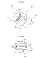
- a notch 136 is formed in an end portion of the outer tube 146 of the first pipe 180.
- Fig. 14B is a diagram as viewed from the arrow R direction illustrated in Fig. 14A .
- the notch 136 is formed as a notch in an end portion on the connection portion 122 side of the outer tube 146.
- the notch 136 is configured of sufficient size to insert a pressing member for releasing the connection of the claw member 129 for connecting the tube portion 120. Explanation is given later regarding the pressing member.
- the notch 136 includes a circumferential direction end face 154 cut along the circumferential direction, and an axial direction end face 156 cut along the axial line 132 direction.
- the inner pipe 118 is exposed at the interior of the notch 136.
- a rib 138 projects out parallel to the axial line 132 from a substantially central position on the circumferential direction end face 154 of the notch 136.
- the rib 138 is formed in a plate shape with a length in the axial line 132 direction substantially the same as the length of the notch 136.
- a joining portion 138A of the rib 138 to the circumferential direction end face 154 is formed where the plate thickness is thinned to enable the rib 138 to be easily cut off.
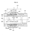
- the first pipe 180 and the second pipe 182 connected by the connection portion 122 can be separated by the following procedure. As shown in the separation procedure illustrated in Fig. 15 and Fig. 16 , a dedicated pressing member 140 is employed to separate the first pipe 180 and the second pipe 182.
- the pressing member 140 includes a curved portion 142 with a curved face that covers the outer peripheral face of the tube portion 120 over substantially half the circumference (length S1 around the curved face).
- the axial line 132 direction length of the curved portion 142 is denoted H1.
- the pressing member 140 also includes a flange portion 144 that bends around from an end portion of the curved portion 142 along the radial direction. The flange portion 144 serves as a pinched portion when the curved portion 142 is being inserted.
- the notch 136 is formed by notching a portion of the tube portion 120 end of the outer tube 146 such that the circumferential direction length S2 of the notch 136 is longer than the circumferential direction length S1 of the pressing member 140 in the curved portion 142 circumferential direction, and the length H2 of the notch 136 in the axial line 132 direction is greater than the length H1 of the curved portion 142.
- the curved portion 142 of the pressing member 140 can accordingly be inserted into the notch 136 such that the curved portion 142 makes contact with the surface of the notch 136.
- the rib 138 projects out from the notch 136.
- the rib 138 projects out at a substantially central portion of the circumferential direction end face 154.
- the separation distance from the side face of the rib 138 to the axial direction end faces 156 of the notch 136 is accordingly less than the circumferential direction width S1 of the curved portion 142.
- the curved portion (plate portion) 142 of the pressing member 140 cannot be inserted into the gap of the notch 136 up to the rib 138.
- the separation procedure is hence to first cut off the rib 138 provided to the notch 136 and insert the pressing member 140 into the notch 136 (see Fig. 15A , Fig. 16A and Fig. 16B ). Cutting off the rib 138 can be easily accomplished at the position of the joining portion 138A since the joining portion 138A is made thinner than the outer tube 146 of the rib 138.
- the pressing member 140 is then moved along the axial direction of the tube portion 120. Namely, the curved portion 142 is inserted between the cap 134 and the tube portion 120, so as to press the end portion 128S of the collet 128 in the arrow Y direction along the surface of the inner pipe 118 (see Fig. 15B and 16C ).
- the collet 128 can accordingly be moved in the arrow Y direction.
- the end portions 128E of the collet 128 ride up the sloping portion 131 of the support ring 130 due to the collet 128 being moved as described above.
- the diameter of the end portions 128E of the collet 128 and the claw member 129 is expanded, thereby releasing the retention performed by the claw member 129.
- retention of the collet 128 provided to connection means of the second pipe 182 is released, and the first pipe 180 and the second pipe 182 can be separated from each other.
- the connected first pipe 180 and second pipe 182 can be disassembled, for example on site, and reassembled.
- the rib 138 provided to the notch 136 needs to be cut off, and so when the rib 138 has been cut off this can serve as evidence that the first pipe 180 and the second pipe 182 have been separated. Since signs of plastic deformation in the joining portion to the outer tube 146 remain when the rib 138 is deformed to a great extent without actually cutting the rib 138 off, such evidence can serve as evidence that the first pipe 180 and the second pipe 182 have been separated.
- the first pipe 180 is a double tube construction of the inner pipe 118 and the outer tube 146.
- a three or more multi-tube construction provided with an intermediate tube between the inner pipe 118 and the outer tube 146 may be employed.
- the single tube configuration may also be employed with integrally molded inner pipe 118 and outer tube 146. Similar advantageous effects can be obtained thereby to those of the double tube construction.
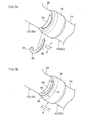
- a fitting structure 160 differs from the fitting structure 110 of the second exemplary embodiment in the configuration of the notch. Explanation focuses on the points of difference.
- the fitting structure 160 includes a first pipe 180 and a second pipe 182, and the first pipe 180 and the second pipe 182 are connected together at a connection portion 122.
- a notch 137 of substantially the same dimensions to that of the notch 136 explained in the first exemplary embodiment is provided to the first pipe 180 in a similar position to the notch 13 6.
- a rib 162 projects out from a first axial direction end face 157 of the notch 137 towards the second axial direction end face 157 (facing along the circumferential direction).
- the rib 162 is formed in a flat plate shape with similar radial direction height dimension to that of the outer tube 146 so as to cover the outer peripheral face of the inner pipe 118.
- the rib 162 is thinned in plate thickness at a joining portion 162A to the axial direction end face 156, enabling the rib 162 to be cut off easily.
- the rib 162 is provided in the vicinity of an axial direction central portion of the end face 156, and a gap portion between the rib 162 and the notch 136 is made smaller than the axial direction length H1 of the pressing member 140 explained in the first exemplary embodiment, such that the curved portion 142 of the pressing member 140 cannot be inserted.
- One end portion of the rib 162 may be configured with a length so as to end part-way along before reaching the second axial direction end face 157.
- the rib 162 must be cut off from the notch 137 in order to insert the curved portion 142 of the pressing member 140 described in the first exemplary embodiment into the notch 137. As a result when the rib 162 has been cut off this can be employed as evidence that the first pipe 180 has been separated.
- Other parts of the configuration are similar to those of the second exemplary embodiment and further explanation thereof is omitted.
- a fitting structure 170 according to a fourth exemplary embodiment differs from the fitting structure 110 of the second exemplary embodiment in the configuration of the notch. Explanation focusses on the points of difference.
- the fitting structure 170 includes a first pipe 180 and a second pipe 182, and the first pipe 180 and the second pipe 182 are connected together by a connection portion 122.
- a notch 172 is provided to the first pipe 180.
- Fig. 18A is a cross-section illustrating a section taken in a direction orthogonal to the axial line 132 as the position of the notch 172
- Fig. 18B is a plan view of a pressing member.
- Fig. 19A is a perspective view of a notch
- Fig. 19B is a perspective view of a pressing member
- Fig. 19C is a diagram of a state in which a pressing member has been inserted into a notch.
- the notch 172 is formed by removing the outer tube 146 of the first pipe 180 from two sides along a tangent 158 to the inner pipe 118 as far as the outer peripheral face of the inner pipe 118.
- the notch 172 can thereby be formed in two locations, facing each other with the inner pipe 118 in between.
- a width dimension H4 of the notch 172 is larger than an axial line direction length H3 (see Fig. 19B ) of curved portions 177 of a U-shaped pressing member 176, described later.
- Two ribs 174 project out from the end faces of the outer tube 146 of the notch 172 along respective axial line 132 directions.
- the pressing member 176 includes two curved portions 177 provided as faces curving around the outer peripheral face of the tube portion 120.
- a flange portion 178 is provided to the curved portions 177 bending out in the radial direction from each end portion of the curved portions 177. End portions of the flange portion 178 extend along the notch 172 so as to integrate the pressing member 176 into a U-shape in plan view.
- the pressing member 176 is inserted into the notches 172 when the rib 174 has been removed, and the curved portion 177 is inserted between the cap 134 and the inner pipe 118 explained in the second exemplary embodiment, pushing down the collet 128.
- the first pipe 180 and the second pipe 182 can accordingly be separated from each other.
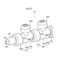
- a fitting structure 190 of a fifth exemplary embodiment differs from the second exemplary embodiment in the configuration of the connection portion to the fitting structure 110. Explanation focusses on the points of difference.
- Fig. 20 illustrates a connected state.
- the fitting structure 190 includes a first pipe 180 and a third pipe 192, and the first pipe 180 and the third pipe 192 are connected together by a connection portion 123 with one-touch connection.
- the first pipe 180 has already been described in the second exemplary embodiment and further explanation is omitted.
- the third pipe 192 includes an internal third flow path 194, and the connection portion 123 is provided at the leading end of the third pipe 192.
- a reduced diameter portion 185 where the tube diameter narrows is provided to the leading end of the third pipe 192, and the connection portion 123 is configured to utilize the reduced diameter portion 185.
- a tube portion 120 of the first pipe 180 as described in the second exemplary embodiment is fitted over the outside of the reduced diameter portion 185.
- O-rings 152 are provided between the reduced diameter portion 185 and the tube portion 120 to prevent water leakage.
- a first flow path 116 of the first pipe 180 such as described in the second exemplary embodiment and a third flow path 194 are accordingly in communication with each other.
- connection portion 123 is configured from two components, a circular ring shaped retention ring 164 and an opening ring 166, dividing the collet 128 of the connection portion 122 as described in the second exemplary embodiment.
- the retention ring 164 is formed such that in cross-section a central portion folds back on itself at an acute angle, and the inner peripheral face side of the retention ring 164 slopes in the arrow Y direction.
- the leading end of the retention ring 164 is in contact with the outer peripheral face of the tube portion 120.
- the tube portion 120 is accordingly retained by the leading end of the retention ring 164, and the tube portion 120 is prevented from coming out in the arrow X direction.
- the opening ring 166 is formed in a circular cylindrical shape, provided to the side face on the insertion opening side of the retention ring 164 (the arrow X direction side).
- the end portion on the retention ring 164 side of the opening ring 166 includes a sloping portion that makes contact with a sloping face of the retention ring 164.
- a transparent cover 168 is provided on the arrow Y direction side of the retention ring 164, surrounding the tube portion 120 and the reduced diameter portion 185. In this state the sloping portion at the leading end of the transparent cover 168 and a sloping portion of the retention ring 164 make contact with each other.
- a cap 135 is also provided to surround the outer periphery of the transparent cover 168, the retention ring 164 and the opening ring 166. Movement of the transparent cover 168, the retention ring 164 and the opening ring 166 in the radial direction is thereby restricted.
- the retention ring 164 can move along the sloping portion at the leading end of the transparent cover 168 by a leading end 166S of the opening ring 166 being moved by the pressing member in the arrow Y direction.
- the diameter of the retention ring 164 thereby expands.
- retention of the tube portion 120 by the retention ring 164 is released, and it becomes possible to remove the tube portion 120.
- Other parts of the configuration are similar to those of the second exemplary embodiment and further explanation is omitted.
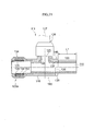
- a header unit 111 includes a first pipe 180 as described in the second exemplary embodiment.
- the first pipe 180 is a double tube construction configured by an inner pipe 118 formed with an internal first flow path 116 and outer tube 146 surrounding the inner pipe 118.
- connection tube portion 120 where the outer tube 146 is removed over a width L1 is formed at a portion at a first end of the first pipe 180, and a connection portion 122a for one-touch connection to a tube portion, not shown in the drawings, fitting over the outside is provided to a portion at the second end of the first pipe 180.
- the connection portion 122a is configured similarly to the connection portion 122 described in the second exemplary embodiment and further explanation is omitted.
- a connection portion 126 for one-touch connection of the branch pipe 124 and a pipe 127 is provided to a leading end of the branch pipe 124.
- a pipe layout header provided with plural branch flow paths can be provided by connecting the tube portion 120 of the header unit 111 to the connection portion of a second header unit, not shown in the drawings.
- a pipe layout header provided with plural branch flow paths can also be provided by connecting the tube portion of the second header unit, not shown in the drawings, to the connection portion 122a of the header unit 111.
- notch 13 6 and the rib 138 of the header unit 111 are described for a case where the notch 136 and the rib 138 as described in the second exemplary embodiment are employed.
- the notch 137 and the rib 162 described in the third exemplary embodiment may be employed, or the notch 172 and the rib 174 described in the fourth exemplary embodiment may also be employed.
- Explanation has further been given of a case in which the connection portion 122 described in the second exemplary embodiment is employed as connection means.
- connection portion 123 described in the fifth exemplary embodiment may also be employed.
- a pipe layout header 112 is configured by connecting a first header unit 113 and a second header unit 114 together with a connection portion 122b.
- Both the first header unit 113 and the second header unit 114 are of similar configuration to the header unit 111 described in the sixth exemplary embodiment. Explanation focuses on the connection portion. For simplicity, explanation is given with portions relating to the first header unit 113 appended with the letter a, and portions relating to the second header unit 114 appended with the letter b.
- connection is made by inserting a tube portion 120a of the first header unit 113 into a connection portion 122b of the second header unit 114.
- the number of branch pipes 124 increases according to the number of pipe members 127a to be connected, and other header units, not shown in the drawings, may be configured simply by connecting together the required number of branch pipes 124 using the method described above.
- a pipe 150 connected to for example a heater, not shown in the drawings, is inserted and fixed to the connection portion 122a of the first header unit 113.
- the pipe layout header 112 and the pipe 150 can accordingly communicate with each other and hot or cold water can be made to flow in the directions of the arrow W1 or the arrow W2.
- the connection portion 122a may also be connected to an elbow base, not shown in the drawings, formed with a bent portion provided with a tube portion at an end portion of the bent portion.
- a rib 138a is removed from a notch 136a on the first header unit 113 and the pressing member 140 described in the second exemplary embodiment is inserted. Connection is thereby released, and the first header unit 113 and the second header unit 114 can be separated. Since it is necessary to remove the rib 138a provided to the notch 136a in order to insert the pressing member 140, if the rib 168a has been removed, this can serve as evidence that the first header unit 113 and the second header unit 114 have been separated.
- connection portion 122 described in the second exemplary embodiment is employed as connection means.
- connection portion 123 described in the fifth exemplary embodiment may also be employed. Any fitting in which connection can be released by inserting the pressing member 140 or the pressing member 176 may employed as a fitting.
Landscapes
- Engineering & Computer Science (AREA)
- General Engineering & Computer Science (AREA)
- Mechanical Engineering (AREA)
- Quick-Acting Or Multi-Walled Pipe Joints (AREA)
- Steam Or Hot-Water Central Heating Systems (AREA)
Applications Claiming Priority (2)
| Application Number | Priority Date | Filing Date | Title |
|---|---|---|---|
| JP2011089994A JP5805980B2 (ja) | 2011-04-14 | 2011-04-14 | 管継手及び配管用ヘッダー |
| JP2011089995A JP5805981B2 (ja) | 2011-04-14 | 2011-04-14 | 継手構造、ヘッダー基体及びヘッダー |
Publications (3)
| Publication Number | Publication Date |
|---|---|
| EP2511583A2 true EP2511583A2 (fr) | 2012-10-17 |
| EP2511583A3 EP2511583A3 (fr) | 2013-05-01 |
| EP2511583B1 EP2511583B1 (fr) | 2016-03-30 |
Family
ID=46022079
Family Applications (1)
| Application Number | Title | Priority Date | Filing Date |
|---|---|---|---|
| EP12164040.3A Active EP2511583B1 (fr) | 2011-04-14 | 2012-04-13 | Structure de raccord, raccord de tuyau et tête de disposition de tuyau |
Country Status (2)
| Country | Link |
|---|---|
| EP (1) | EP2511583B1 (fr) |
| CN (2) | CN202629435U (fr) |
Cited By (7)
| Publication number | Priority date | Publication date | Assignee | Title |
|---|---|---|---|---|
| ITRM20130456A1 (it) * | 2013-08-05 | 2015-02-06 | Vifra S R L | Dispositivo di giunzione idraulico |
| US9574691B1 (en) * | 2016-05-04 | 2017-02-21 | Quick Fitting, Inc. | Hybrid push-to-connect fitting device, arrangement and method |
| US9671049B1 (en) | 2016-07-27 | 2017-06-06 | Quick Fitting, Inc. | Hybrid push-to-connect fitting device and assembly |
| US9857006B2 (en) | 2016-03-31 | 2018-01-02 | Quick Fitting, Inc. | Retaining ring for pipe joint devices |
| US10400929B2 (en) | 2017-09-27 | 2019-09-03 | Quick Fitting, Inc. | Fitting device, arrangement and method |
| US10969047B1 (en) | 2020-01-29 | 2021-04-06 | Quick Fitting Holding Company, Llc | Electrical conduit fitting and assembly |
| US11035510B1 (en) | 2020-01-31 | 2021-06-15 | Quick Fitting Holding Company, Llc | Electrical conduit fitting and assembly |
Families Citing this family (1)
| Publication number | Priority date | Publication date | Assignee | Title |
|---|---|---|---|---|
| CN202629435U (zh) * | 2011-04-14 | 2012-12-26 | 株式会社普利司通 | 接头构造、管接头及配管用集管 |
Citations (1)
| Publication number | Priority date | Publication date | Assignee | Title |
|---|---|---|---|---|
| JP2007100807A (ja) | 2005-10-03 | 2007-04-19 | Bridgestone Corp | ヘッダ−基体及びその製法並びにこれを用いたヘッダー構造 |
Family Cites Families (10)
| Publication number | Priority date | Publication date | Assignee | Title |
|---|---|---|---|---|
| US3447819A (en) * | 1966-12-30 | 1969-06-03 | Adolph W Borsum | Push-pull connector having combined seal and locking ring |
| US4313331A (en) * | 1978-06-02 | 1982-02-02 | Nycoil Company | Method of manufacturing a metallic retaining ring for a tube |
| IT8583626A0 (it) * | 1985-11-25 | 1985-11-25 | Vulcano Di Pozzi Gian Carlo | Raccordo autobloccante "unisex" col "clik" per attacco rapido di tubi in materiale plastico. |
| JP4023430B2 (ja) * | 2003-02-21 | 2007-12-19 | 株式会社デンソー | 二重管継手構造 |
| DE202004010967U1 (de) * | 2004-07-14 | 2004-12-02 | Cooler Master Co., Ltd., Chung-Ho | Kupplungsverbindung für einen flüssigkeitsgekühlten Wärmeableiter |
| US7469933B2 (en) * | 2005-03-11 | 2008-12-30 | The Gates Corporation | Quick connect coupling with disconnect lock |
| EP1859190B1 (fr) * | 2005-03-11 | 2017-12-13 | Gates Corporation | Raccord rapide a verrou de degagement |
| US7950619B2 (en) * | 2008-04-03 | 2011-05-31 | Ckd Corporation | Fluid device mounting structure |
| CN201526766U (zh) * | 2009-05-21 | 2010-07-14 | 厦门建霖工业有限公司 | 一种管件快速装配结构 |
| CN202629435U (zh) * | 2011-04-14 | 2012-12-26 | 株式会社普利司通 | 接头构造、管接头及配管用集管 |
-
2012
- 2012-04-11 CN CN2012201533442U patent/CN202629435U/zh not_active Withdrawn - After Issue
- 2012-04-11 CN CN201210106432.1A patent/CN102734584B/zh active Active
- 2012-04-13 EP EP12164040.3A patent/EP2511583B1/fr active Active
Patent Citations (1)
| Publication number | Priority date | Publication date | Assignee | Title |
|---|---|---|---|---|
| JP2007100807A (ja) | 2005-10-03 | 2007-04-19 | Bridgestone Corp | ヘッダ−基体及びその製法並びにこれを用いたヘッダー構造 |
Cited By (8)
| Publication number | Priority date | Publication date | Assignee | Title |
|---|---|---|---|---|
| ITRM20130456A1 (it) * | 2013-08-05 | 2015-02-06 | Vifra S R L | Dispositivo di giunzione idraulico |
| US9857006B2 (en) | 2016-03-31 | 2018-01-02 | Quick Fitting, Inc. | Retaining ring for pipe joint devices |
| US10670173B2 (en) | 2016-03-31 | 2020-06-02 | Quick Fitting, Inc. | Locking pipe joint device with indicator |
| US9574691B1 (en) * | 2016-05-04 | 2017-02-21 | Quick Fitting, Inc. | Hybrid push-to-connect fitting device, arrangement and method |
| US9671049B1 (en) | 2016-07-27 | 2017-06-06 | Quick Fitting, Inc. | Hybrid push-to-connect fitting device and assembly |
| US10400929B2 (en) | 2017-09-27 | 2019-09-03 | Quick Fitting, Inc. | Fitting device, arrangement and method |
| US10969047B1 (en) | 2020-01-29 | 2021-04-06 | Quick Fitting Holding Company, Llc | Electrical conduit fitting and assembly |
| US11035510B1 (en) | 2020-01-31 | 2021-06-15 | Quick Fitting Holding Company, Llc | Electrical conduit fitting and assembly |
Also Published As
| Publication number | Publication date |
|---|---|
| CN102734584A (zh) | 2012-10-17 |
| CN202629435U (zh) | 2012-12-26 |
| EP2511583A3 (fr) | 2013-05-01 |
| CN102734584B (zh) | 2016-08-03 |
| EP2511583B1 (fr) | 2016-03-30 |
Similar Documents
| Publication | Publication Date | Title |
|---|---|---|
| EP2511583B1 (fr) | Structure de raccord, raccord de tuyau et tête de disposition de tuyau | |
| US20210071793A1 (en) | Fluid connector | |
| CA2960498C (fr) | Dispositif de raccord rapide et methode d'etablissement et de verification d'une connexion etanche entre des conduits | |
| EP3332938B1 (fr) | Raccord de conduite de carburant, procédé de fabrication | |
| US6158784A (en) | Connector for tubular members | |
| US6439617B1 (en) | Coupler for a pipe or hose section | |
| US5513882A (en) | Universal non-threaded pipe connector system | |
| JP2005509824A (ja) | クイックリリース型管継手 | |
| CA2720485A1 (fr) | Ensemble dispositif de fixation de tuyau mecanique | |
| AU2019339784B2 (en) | Corrugated piping assembly and sleeve for same | |
| WO2008067405A2 (fr) | Raccord de conduite et procédé de raccordement de conduite | |
| CN100424398C (zh) | 具有角位锁定装置的插塞连接器 | |
| CN103938675B (zh) | 卫生配件和用于该卫生配件的流体导管 | |
| CN120917258A (zh) | 用于将管道和功能单元连接的管件和系统 | |
| EP3388727B1 (fr) | Assemblage de connexion pour un système de chauffage et/ou d'air conditioné | |
| JP5805980B2 (ja) | 管継手及び配管用ヘッダー | |
| CN118110856A (zh) | 母接头以及接头组件 | |
| US20250383039A1 (en) | Press fitting | |
| JP2023547914A (ja) | 流体接続アセンブリ | |
| JP5805981B2 (ja) | 継手構造、ヘッダー基体及びヘッダー | |
| EP4538575A1 (fr) | Ensemble de raccordement de fluide | |
| CN1646845B (zh) | 铜管段的连接方法 | |
| EP3467368A1 (fr) | Couplage hydraulique | |
| EP2975312A1 (fr) | Système de refroidissement d'un flux ou pour extraire la chaleur d'un flux dans un pipeline et/ou pour extraire la chaleur hors de l'environnement d'un pipeline | |
| CN119365715A (zh) | 管道配件 |
Legal Events
| Date | Code | Title | Description |
|---|---|---|---|
| PUAI | Public reference made under article 153(3) epc to a published international application that has entered the european phase |
Free format text: ORIGINAL CODE: 0009012 |
|
| AK | Designated contracting states |
Kind code of ref document: A2 Designated state(s): AL AT BE BG CH CY CZ DE DK EE ES FI FR GB GR HR HU IE IS IT LI LT LU LV MC MK MT NL NO PL PT RO RS SE SI SK SM TR |
|
| AX | Request for extension of the european patent |
Extension state: BA ME |
|
| PUAL | Search report despatched |
Free format text: ORIGINAL CODE: 0009013 |
|
| AK | Designated contracting states |
Kind code of ref document: A3 Designated state(s): AL AT BE BG CH CY CZ DE DK EE ES FI FR GB GR HR HU IE IS IT LI LT LU LV MC MK MT NL NO PL PT RO RS SE SI SK SM TR |
|
| AX | Request for extension of the european patent |
Extension state: BA ME |
|
| RIC1 | Information provided on ipc code assigned before grant |
Ipc: F16L 37/091 20060101ALI20130328BHEP Ipc: F16L 37/084 20060101AFI20130328BHEP |
|
| 17P | Request for examination filed |
Effective date: 20131031 |
|
| RBV | Designated contracting states (corrected) |
Designated state(s): AL AT BE BG CH CY CZ DE DK EE ES FI FR GB GR HR HU IE IS IT LI LT LU LV MC MK MT NL NO PL PT RO RS SE SI SK SM TR |
|
| RIC1 | Information provided on ipc code assigned before grant |
Ipc: F16L 37/084 20060101AFI20150715BHEP Ipc: F16L 37/091 20060101ALI20150715BHEP |
|
| GRAP | Despatch of communication of intention to grant a patent |
Free format text: ORIGINAL CODE: EPIDOSNIGR1 |
|
| INTG | Intention to grant announced |
Effective date: 20150911 |
|
| GRAS | Grant fee paid |
Free format text: ORIGINAL CODE: EPIDOSNIGR3 |
|
| GRAA | (expected) grant |
Free format text: ORIGINAL CODE: 0009210 |
|
| AK | Designated contracting states |
Kind code of ref document: B1 Designated state(s): AL AT BE BG CH CY CZ DE DK EE ES FI FR GB GR HR HU IE IS IT LI LT LU LV MC MK MT NL NO PL PT RO RS SE SI SK SM TR |
|
| REG | Reference to a national code |
Ref country code: GB Ref legal event code: FG4D |
|
| REG | Reference to a national code |
Ref country code: CH Ref legal event code: EP |
|
| REG | Reference to a national code |
Ref country code: AT Ref legal event code: REF Ref document number: 785781 Country of ref document: AT Kind code of ref document: T Effective date: 20160415 |
|
| REG | Reference to a national code |
Ref country code: IE Ref legal event code: FG4D |
|
| REG | Reference to a national code |
Ref country code: DE Ref legal event code: R096 Ref document number: 602012016177 Country of ref document: DE |
|
| REG | Reference to a national code |
Ref country code: LT Ref legal event code: MG4D |
|
| PG25 | Lapsed in a contracting state [announced via postgrant information from national office to epo] |
Ref country code: GR Free format text: LAPSE BECAUSE OF FAILURE TO SUBMIT A TRANSLATION OF THE DESCRIPTION OR TO PAY THE FEE WITHIN THE PRESCRIBED TIME-LIMIT Effective date: 20160701 Ref country code: FI Free format text: LAPSE BECAUSE OF FAILURE TO SUBMIT A TRANSLATION OF THE DESCRIPTION OR TO PAY THE FEE WITHIN THE PRESCRIBED TIME-LIMIT Effective date: 20160330 Ref country code: NO Free format text: LAPSE BECAUSE OF FAILURE TO SUBMIT A TRANSLATION OF THE DESCRIPTION OR TO PAY THE FEE WITHIN THE PRESCRIBED TIME-LIMIT Effective date: 20160630 Ref country code: HR Free format text: LAPSE BECAUSE OF FAILURE TO SUBMIT A TRANSLATION OF THE DESCRIPTION OR TO PAY THE FEE WITHIN THE PRESCRIBED TIME-LIMIT Effective date: 20160330 |
|
| REG | Reference to a national code |
Ref country code: NL Ref legal event code: MP Effective date: 20160330 |
|
| REG | Reference to a national code |
Ref country code: AT Ref legal event code: MK05 Ref document number: 785781 Country of ref document: AT Kind code of ref document: T Effective date: 20160330 |
|
| PG25 | Lapsed in a contracting state [announced via postgrant information from national office to epo] |
Ref country code: RS Free format text: LAPSE BECAUSE OF FAILURE TO SUBMIT A TRANSLATION OF THE DESCRIPTION OR TO PAY THE FEE WITHIN THE PRESCRIBED TIME-LIMIT Effective date: 20160330 Ref country code: BE Free format text: LAPSE BECAUSE OF NON-PAYMENT OF DUE FEES Effective date: 20160430 Ref country code: LV Free format text: LAPSE BECAUSE OF FAILURE TO SUBMIT A TRANSLATION OF THE DESCRIPTION OR TO PAY THE FEE WITHIN THE PRESCRIBED TIME-LIMIT Effective date: 20160330 Ref country code: LT Free format text: LAPSE BECAUSE OF FAILURE TO SUBMIT A TRANSLATION OF THE DESCRIPTION OR TO PAY THE FEE WITHIN THE PRESCRIBED TIME-LIMIT Effective date: 20160330 Ref country code: SE Free format text: LAPSE BECAUSE OF FAILURE TO SUBMIT A TRANSLATION OF THE DESCRIPTION OR TO PAY THE FEE WITHIN THE PRESCRIBED TIME-LIMIT Effective date: 20160330 |
|
| PG25 | Lapsed in a contracting state [announced via postgrant information from national office to epo] |
Ref country code: NL Free format text: LAPSE BECAUSE OF FAILURE TO SUBMIT A TRANSLATION OF THE DESCRIPTION OR TO PAY THE FEE WITHIN THE PRESCRIBED TIME-LIMIT Effective date: 20160330 |
|
| PG25 | Lapsed in a contracting state [announced via postgrant information from national office to epo] |
Ref country code: EE Free format text: LAPSE BECAUSE OF FAILURE TO SUBMIT A TRANSLATION OF THE DESCRIPTION OR TO PAY THE FEE WITHIN THE PRESCRIBED TIME-LIMIT Effective date: 20160330 Ref country code: PL Free format text: LAPSE BECAUSE OF FAILURE TO SUBMIT A TRANSLATION OF THE DESCRIPTION OR TO PAY THE FEE WITHIN THE PRESCRIBED TIME-LIMIT Effective date: 20160330 Ref country code: IS Free format text: LAPSE BECAUSE OF FAILURE TO SUBMIT A TRANSLATION OF THE DESCRIPTION OR TO PAY THE FEE WITHIN THE PRESCRIBED TIME-LIMIT Effective date: 20160730 |
|
| PG25 | Lapsed in a contracting state [announced via postgrant information from national office to epo] |
Ref country code: CZ Free format text: LAPSE BECAUSE OF FAILURE TO SUBMIT A TRANSLATION OF THE DESCRIPTION OR TO PAY THE FEE WITHIN THE PRESCRIBED TIME-LIMIT Effective date: 20160330 Ref country code: SK Free format text: LAPSE BECAUSE OF FAILURE TO SUBMIT A TRANSLATION OF THE DESCRIPTION OR TO PAY THE FEE WITHIN THE PRESCRIBED TIME-LIMIT Effective date: 20160330 Ref country code: PT Free format text: LAPSE BECAUSE OF FAILURE TO SUBMIT A TRANSLATION OF THE DESCRIPTION OR TO PAY THE FEE WITHIN THE PRESCRIBED TIME-LIMIT Effective date: 20160801 Ref country code: AT Free format text: LAPSE BECAUSE OF FAILURE TO SUBMIT A TRANSLATION OF THE DESCRIPTION OR TO PAY THE FEE WITHIN THE PRESCRIBED TIME-LIMIT Effective date: 20160330 Ref country code: ES Free format text: LAPSE BECAUSE OF FAILURE TO SUBMIT A TRANSLATION OF THE DESCRIPTION OR TO PAY THE FEE WITHIN THE PRESCRIBED TIME-LIMIT Effective date: 20160330 Ref country code: SM Free format text: LAPSE BECAUSE OF FAILURE TO SUBMIT A TRANSLATION OF THE DESCRIPTION OR TO PAY THE FEE WITHIN THE PRESCRIBED TIME-LIMIT Effective date: 20160330 Ref country code: RO Free format text: LAPSE BECAUSE OF FAILURE TO SUBMIT A TRANSLATION OF THE DESCRIPTION OR TO PAY THE FEE WITHIN THE PRESCRIBED TIME-LIMIT Effective date: 20160330 |
|
| REG | Reference to a national code |
Ref country code: CH Ref legal event code: PL |
|
| PG25 | Lapsed in a contracting state [announced via postgrant information from national office to epo] |
Ref country code: BE Free format text: LAPSE BECAUSE OF FAILURE TO SUBMIT A TRANSLATION OF THE DESCRIPTION OR TO PAY THE FEE WITHIN THE PRESCRIBED TIME-LIMIT Effective date: 20160330 Ref country code: IT Free format text: LAPSE BECAUSE OF FAILURE TO SUBMIT A TRANSLATION OF THE DESCRIPTION OR TO PAY THE FEE WITHIN THE PRESCRIBED TIME-LIMIT Effective date: 20160330 |
|
| REG | Reference to a national code |
Ref country code: DE Ref legal event code: R097 Ref document number: 602012016177 Country of ref document: DE |
|
| REG | Reference to a national code |
Ref country code: IE Ref legal event code: MM4A |
|
| PG25 | Lapsed in a contracting state [announced via postgrant information from national office to epo] |
Ref country code: LI Free format text: LAPSE BECAUSE OF NON-PAYMENT OF DUE FEES Effective date: 20160430 Ref country code: CH Free format text: LAPSE BECAUSE OF NON-PAYMENT OF DUE FEES Effective date: 20160430 Ref country code: DK Free format text: LAPSE BECAUSE OF FAILURE TO SUBMIT A TRANSLATION OF THE DESCRIPTION OR TO PAY THE FEE WITHIN THE PRESCRIBED TIME-LIMIT Effective date: 20160330 |
|
| PLBE | No opposition filed within time limit |
Free format text: ORIGINAL CODE: 0009261 |
|
| STAA | Information on the status of an ep patent application or granted ep patent |
Free format text: STATUS: NO OPPOSITION FILED WITHIN TIME LIMIT |
|
| 26N | No opposition filed |
Effective date: 20170103 |
|
| REG | Reference to a national code |
Ref country code: FR Ref legal event code: ST Effective date: 20170215 |
|
| PG25 | Lapsed in a contracting state [announced via postgrant information from national office to epo] |
Ref country code: FR Free format text: LAPSE BECAUSE OF NON-PAYMENT OF DUE FEES Effective date: 20160530 |
|
| PG25 | Lapsed in a contracting state [announced via postgrant information from national office to epo] |
Ref country code: SI Free format text: LAPSE BECAUSE OF FAILURE TO SUBMIT A TRANSLATION OF THE DESCRIPTION OR TO PAY THE FEE WITHIN THE PRESCRIBED TIME-LIMIT Effective date: 20160330 Ref country code: IE Free format text: LAPSE BECAUSE OF NON-PAYMENT OF DUE FEES Effective date: 20160413 |
|
| PG25 | Lapsed in a contracting state [announced via postgrant information from national office to epo] |
Ref country code: CY Free format text: LAPSE BECAUSE OF FAILURE TO SUBMIT A TRANSLATION OF THE DESCRIPTION OR TO PAY THE FEE WITHIN THE PRESCRIBED TIME-LIMIT Effective date: 20160330 Ref country code: HU Free format text: LAPSE BECAUSE OF FAILURE TO SUBMIT A TRANSLATION OF THE DESCRIPTION OR TO PAY THE FEE WITHIN THE PRESCRIBED TIME-LIMIT; INVALID AB INITIO Effective date: 20120413 |
|
| PG25 | Lapsed in a contracting state [announced via postgrant information from national office to epo] |
Ref country code: TR Free format text: LAPSE BECAUSE OF FAILURE TO SUBMIT A TRANSLATION OF THE DESCRIPTION OR TO PAY THE FEE WITHIN THE PRESCRIBED TIME-LIMIT Effective date: 20160330 Ref country code: MC Free format text: LAPSE BECAUSE OF FAILURE TO SUBMIT A TRANSLATION OF THE DESCRIPTION OR TO PAY THE FEE WITHIN THE PRESCRIBED TIME-LIMIT Effective date: 20160330 Ref country code: MT Free format text: LAPSE BECAUSE OF NON-PAYMENT OF DUE FEES Effective date: 20160430 Ref country code: MK Free format text: LAPSE BECAUSE OF FAILURE TO SUBMIT A TRANSLATION OF THE DESCRIPTION OR TO PAY THE FEE WITHIN THE PRESCRIBED TIME-LIMIT Effective date: 20160330 Ref country code: LU Free format text: LAPSE BECAUSE OF NON-PAYMENT OF DUE FEES Effective date: 20160413 |
|
| PG25 | Lapsed in a contracting state [announced via postgrant information from national office to epo] |
Ref country code: BG Free format text: LAPSE BECAUSE OF FAILURE TO SUBMIT A TRANSLATION OF THE DESCRIPTION OR TO PAY THE FEE WITHIN THE PRESCRIBED TIME-LIMIT Effective date: 20160330 |
|
| PG25 | Lapsed in a contracting state [announced via postgrant information from national office to epo] |
Ref country code: AL Free format text: LAPSE BECAUSE OF FAILURE TO SUBMIT A TRANSLATION OF THE DESCRIPTION OR TO PAY THE FEE WITHIN THE PRESCRIBED TIME-LIMIT Effective date: 20160330 |
|
| P01 | Opt-out of the competence of the unified patent court (upc) registered |
Effective date: 20230531 |
|
| PGFP | Annual fee paid to national office [announced via postgrant information from national office to epo] |
Ref country code: DE Payment date: 20250422 Year of fee payment: 14 |
|
| PGFP | Annual fee paid to national office [announced via postgrant information from national office to epo] |
Ref country code: GB Payment date: 20250423 Year of fee payment: 14 |