EP2511667B1 - Vorrichtung zum Positionieren eines Teils - Google Patents
Vorrichtung zum Positionieren eines Teils Download PDFInfo
- Publication number
- EP2511667B1 EP2511667B1 EP12002625.7A EP12002625A EP2511667B1 EP 2511667 B1 EP2511667 B1 EP 2511667B1 EP 12002625 A EP12002625 A EP 12002625A EP 2511667 B1 EP2511667 B1 EP 2511667B1
- Authority
- EP
- European Patent Office
- Prior art keywords
- base part
- spikes
- holder
- mandrels
- base
- Prior art date
- Legal status (The legal status is an assumption and is not a legal conclusion. Google has not performed a legal analysis and makes no representation as to the accuracy of the status listed.)
- Active
Links
Images
Classifications
-
- G—PHYSICS
- G01—MEASURING; TESTING
- G01D—MEASURING NOT SPECIALLY ADAPTED FOR A SPECIFIC VARIABLE; ARRANGEMENTS FOR MEASURING TWO OR MORE VARIABLES NOT COVERED IN A SINGLE OTHER SUBCLASS; TARIFF METERING APPARATUS; MEASURING OR TESTING NOT OTHERWISE PROVIDED FOR
- G01D11/00—Component parts of measuring arrangements not specially adapted for a specific variable
- G01D11/30—Supports specially adapted for an instrument; Supports specially adapted for a set of instruments
-
- G—PHYSICS
- G01—MEASURING; TESTING
- G01N—INVESTIGATING OR ANALYSING MATERIALS BY DETERMINING THEIR CHEMICAL OR PHYSICAL PROPERTIES
- G01N23/00—Investigating or analysing materials by the use of wave or particle radiation, e.g. X-rays or neutrons, not covered by groups G01N3/00 – G01N17/00, G01N21/00 or G01N22/00
- G01N23/02—Investigating or analysing materials by the use of wave or particle radiation, e.g. X-rays or neutrons, not covered by groups G01N3/00 – G01N17/00, G01N21/00 or G01N22/00 by transmitting the radiation through the material
- G01N23/04—Investigating or analysing materials by the use of wave or particle radiation, e.g. X-rays or neutrons, not covered by groups G01N3/00 – G01N17/00, G01N21/00 or G01N22/00 by transmitting the radiation through the material and forming images of the material
- G01N23/046—Investigating or analysing materials by the use of wave or particle radiation, e.g. X-rays or neutrons, not covered by groups G01N3/00 – G01N17/00, G01N21/00 or G01N22/00 by transmitting the radiation through the material and forming images of the material using tomography, e.g. computed tomography [CT]
-
- G—PHYSICS
- G01—MEASURING; TESTING
- G01N—INVESTIGATING OR ANALYSING MATERIALS BY DETERMINING THEIR CHEMICAL OR PHYSICAL PROPERTIES
- G01N2223/00—Investigating materials by wave or particle radiation
- G01N2223/30—Accessories, mechanical or electrical features
- G01N2223/309—Accessories, mechanical or electrical features support of sample holder
Definitions
- the invention is directed to an apparatus for variable, i. individually adjustable positioning of a part, in particular of a sample body to be examined or measured, which is preferably fixed on a sample holder, in particular in the context of a testing, control, measuring and / or examination device, with a receiving part for supporting the sample holder for the part to be positioned.
- the positioning of a part in the context of a testing, control, measuring or investigation method completely different principles than when processing a workpiece, especially in non-contact testing, control, measurement or investigation methods such as. X-ray method, computed tomography method, laser measurement , Ultrasound procedure, white light scanner method or even with an optical inspection. Because in this case no forces act on the part to be examined, so that the positioning device can be made much more filigree than in the fixation of a workpiece to be machined.
- a holding device and / or a carrier material which (s) has a lower density than the part to be X-rayed, and a recording to this at a desired location, eg. B. in an X-ray machine to position.
- a carrier material also referred to below as a sample carrier
- a carrier material with a low density
- this support material must ensure a position suitable for the measurement and a firm fit of the part during the entire examination period, as a prerequisite for good results of the X-ray examination.
- the carrier material must be adapted, ie processed and then be connected to a recording, z. B. with double-sided tape.
- the mostly metallic recording is directly in the machine or on an adapter, which depends on the manufacturer of the device in question, for example.
- X-ray machine aligned and fixed.
- Styrofoam To the carrier material, for. Styrofoam, to adapt to a part to be X-rayed, it must be processed. Since the preparation of carriers from z. As Styrofoam, which must ensure optimum positioning and a secure fit is relatively complex, such carriers are often difficult to make and are therefore only partially feasible. Because Styrofoam can be bad, difficult and only with sharp or hot tools such. As with carpet knives, hot wire cutters and on top of only rough edit. By working with heat, in the area to be examined, the machined surface becomes unusable for certain parts, because this results in a change in density.
- the polystyrene surface to be bonded must be flat.
- the unavoidable, even slight waviness of the base surface causes it locally lifts off from the tape and thereby, on the only remaining adhesive lines, the mechanical stability of the attachment of the sample holder on the bottom disk in question.
- a wobbling sample in the course of its rotation in computed tomography renders the measurement unusable. If this is not the case, this can lead to unwanted solution of the carrier material, which leads to shake. If this is noticed during the final inspection, the carrier material must be reworked again.
- the contact surface of the foam must be well preprocessed, i. even and fat-free. Then, adhesive strips are cut and glued. The sample or a sample holder is pressed and must be removed after the measurement, as well as the adhesive strip. These steps must be repeated every time a new measurement is taken, which is very time consuming and annoying. A flexible positioning is not possible. The sample or the sample holder may become loose during the measurement, which leads to incorrect measurements. In that case, the adhesive strips must be removed from the base plate. Positional corrections are possible only by repeating the aforementioned steps. Further, not all types of foamed materials can be used, e.g. no floral foam. Similar disadvantages arise when using other adhesives.
- the invention initiates the problem of providing a device in which the simplest possible way a flexible and stable and secure connection between an example. Foamed sample carrier on the one hand and this support supporting support on the other hand can be guaranteed.
- the object is achieved in a device according to the invention according to the independent claim 1, or a method according to claim 14, characterized in that the sample holder has a plurality of thorns, which extend away from a base part and the free ends on one side, so that thereon the sample carrier is pluggable.
- the mandrels may have approximately the geometry of nail-shaped pins.
- a simple, fast, flexible positioning of the carrier is made possible by attaching foamed carrier materials to the receptacle, because the pins penetrate by clamping into the foamed carrier material and provide by the static friction of their lateral surfaces a mechanically reliable connection between the carrier material and recording, but at the same time also easily releasable by tensile stress connection again. This leads to reliable results.
- the bonding surfaces do not need to be specially machined, resulting in time and material savings. These advantages also make automation of the positioning conceivable.
- the contact surface of the sample / the sample carrier need only be roughly preprocessed.
- the sample or sample holder is attached to the transducer in the desired position.
- the sample or the sample carrier can be plugged in any position.
- a position correction is always easy to do.
- no adhesive material is needed, and after the measurement, the sample holder can be easily removed again. There are no adhesive residues left on the sample carrier. After all, almost all foamed materials can be used.
- the device according to the invention can be positioned alone or with a base plate via an adapter or directly in the device, for example on a turntable thereof; the respective assembly technology depends on the manufacturer of the testing, control, measuring or examination device.
- the device according to the invention can be connected to a base plate at least by means of magnets and, for example, also by screwing, gluing, pinning, which can be positioned on an adapter or directly on a turntable, according to the specifications of the manufacturer of the test, control, measuring, or examination apparatus.
- connection between the adapter and the Device according to the invention also take place in different ways in addition to magnetic, for example by fitting, pinning, by screwing od.
- connection has proved to be favorable that several or all mandrels are parallel to each other. This facilitates the attachment of a carrier.
- one or more mandrels can not run parallel to the others, but obliquely or even transversely to it.
- spines are arranged in a regular grid. It may be a square grid, similar to the crossing points of the lines in a crossword puzzle, or a triangular grid, similar to the crossing points of the lines in a Halma game, or in the form of a circular grid, with the mandrels at the intersections of concentric circles with rays radiating away from the center of the circles in all directions. In addition, however, irregular arrangements are conceivable.
- a thread has proved to be suitable, the depression between two adjacent thread pitches being considerably smaller than the shaft diameter or else the shaft radius, for example when the depression is between two adjacent thread pitches
- Thread pitches is less than 2 millimeters, preferably less than 1.5 millimeters, in particular less than 1 millimeter.
- the cross section of the shank or shank main body can also deviate from a circular shape and, for example, be angular or even cross-shaped or star-shaped.
- the invention recommends that one, several or all mandrels have a sharp, sharp-edged or at least one rounded end on the one hand and at the opposite end preferably a head-like broadening, thickening or other measure, which serves the anchoring in a base part.
- a broadening is to be achieved that the mandrels can solve either by shaking or by turning the base.
- the head-like broadening or thickening is completely overlapped by a part of the base part.
- mandrels have approximately the same cross sections in their shank region, for example circular cross sections having a diameter of 0.2 mm or more, preferably 0.5 mm or more, in particular 1.0 mm or more, and / or with a diameter of 20 mm or less, in particular with a diameter of 7 mm or less, in particular with a diameter of 5 mm or less.
- the spikes may taper upwards and be shaped, for example, conical or conical.
- mandrels In order to limit the force required to press the sample carrier, mandrels should be provided with smooth lateral surfaces. Mandrels with structured surfaces bring about a stabilization of a set position or indentation depth and should therefore also be present.
- mandrels can be provided with different lengths, so that at the same time when pressing all mandrels must not penetrate into the sample carrier and a correspondingly reduced force at the beginning of the pressing still allows a fine adjustment of the sample carrier.
- thorns may have equal lengths, for example lengths of 2 mm or more, preferably 5 mm or more, in particular 10 mm or more, and / or lengths of 200 mm or less, preferably 100 mm or less, especially 70 mm or less.
- mandrels of different lengths are preferably arranged distributed over the supporting plate, in particular distributed by two or three different lengths. This provides the advantage, first with positioning the sample holder with little pressure to let the longer pins penetrate into this, and then, after so successful positioning, the pressure to penetrate the other (shorter) pins can increase without the Sample carrier can unintentionally dodge.
- mandrels of the same length can each be arranged in a grid, wherein a plurality of such gratings can be interlocked, or individual mandrels of different lengths are arranged at entangled positions of a common grid.
- longer spines smooth, shorter mandrels profiled lateral surfaces. This has the consequence that the pressure force during the alignment phase is relatively low, while at the end also reach the locking of the set position causing mandrels with textured lateral surfaces into engagement and finally hold the sample carrier immovable and support.
- the projecting ends of the base can be truncated, rounded, but also attaching protective mechanisms, for example, a cover or 2 side shedding half-shells or others, can contribute to the protection.
- thorns should be made of a solid material, in particular of metal or plastic.
- mandrels are made of a stainless material or have corrosion protection, for example. Of zinc or brass.
- the mandrels are firmly connected to the base part, preferably partially embedded therein, in particular cast with their rear ends, preferably in plastic, in particular in a plate made of plastic.
- a particularly intensive type of connection is also obtained when thorns and base plate are made by simultaneous casting or spraying as possible.
- a positive engagement can also be achieved by nailing or pin-shaped mandrels inserted through a perforated plate and glued, clamped or pressed therein. Both when gluing and when embedding the free ends of widened (nail) heads may be excluded from the positive locking; Nevertheless, these such exposed end faces can, for example, lie in a common alignment with the underside of the relevant anchorage plate.
- the base part comprises a plate which has / have a circumferential collar along its circumference /.
- a collar which preferably projects upwards, can be used to remove liquids dripping from a sample part to be measured, for example oil, catch.
- the base part may comprise a plate with fastening devices, in particular on its base facing away from the thorns.
- These fastening devices may, for example, be holes for screws, or, for example, permanent magnets.
- the invention proposes that these are held by a template.
- the base part has a circular disk shape, for example with a diameter of 1 cm or more, preferably 2 cm or more, in particular 5 cm or more, and / or with a diameter of 100 cm or less, preferably 50 cm or less, especially 20 cm or less.
- the height of a circular disk-shaped base part can be between 2 mm and 70 mm, preferably between 3 mm and 50 mm.
- the base should have a flat bottom. This is preferably polished to allow a smooth moving.
- the base part may comprise a base plate of a rigid and heavy material, preferably of an inorganic material such as metal or stone.
- the base part comprises a preferably top-side layer or plate, wherein the mandrels are embedded.
- embedding ie flowing through the still liquid embedding material, a particularly intimate form-fitting achieved.
- the base part at least partially consists of an organic material, preferably of synthetic resin, in particular of a casting resin, the preferably pin-shaped mandrels can be embedded directly.
- These pin-like mandrels may be similar to nails, i. with a widening away from its tip, for example in the form of a preferably flat head.
- the invention undergoes further optimization in that the base part has a two-layer structure. It can be provided according to the invention that there is a layer of an organic material above a layer of an inorganic material. These layers should run parallel to each other and in the most intimate, full-surface contact with each other.
- the layers of organic and inorganic material should be connected to one another in a planar manner, in particular in that the organic layer is formed directly on or on the inorganic layer.
- the invention recommends that the base part has a circumferential, raised edge, preferably in the form of a Tropfterrorismbordes.
- a relatively flat but nevertheless raised rim can be produced relatively easily by using a suitable combination of cast resin and (peripheral) mold for its molding, in particular a combination in which the (peripheral) mold is wetted by the cast resin.
- a higher edge could be made by attaching a raised ring or tube to the base.
- the base of a dish-like collecting vessel or a tubular film may optionally be inserted or clamped between the base part and the base plate, possibly with the insertion of one or more sealing rings, for example O. rings.
- the base part or the base plate can also have a centering aid, so that its own positioning, but also the positioning of the actually to be measured or examined part, is facilitated.
- the base part can be mounted on a base or mounting plate, on a turntable or an adapter or directly in the relevant measuring and / or examination device and is provided for this purpose with suitable connection or mounting means.
- connection or mounting means are at least magnetic body, plus optionally screw or clamping means or any other type of (preferably releasable) fastener.
- a foam block consisting of foamed cells, for example a foamed, acid-cured phenolic or resole resin, and in which the cells disintegrate by mechanical working, is now used as sample holder.
- the part to be positioned can be placed on the support and / or even pressed into the surface of the carrier.
- the carrier is deformable by a depression of the part, so that it subsequently forms a frictional engagement with the pressed-in part.
- the support consists of a foamed material in which the cells are protected by mechanical means Stress, eg by pressure, are destroyed, and / or which is made of the base material phenol resin or Resolharz, preferably by foaming and optionally acid curing.
- a sample body 1 is used, which is fixed directly to a carrier material - also referred to below as a sample carrier 2.
- Foam material can be used, for example, for the sample carrier 2, preferably a foamed, in particular acid-cured phenolic or resole resin.
- a phenolic or Resolharz foam has the advantage that it deforms by slight impressions and thus with commercially available tools, eg. As a spatula, wallpaper knife, so relatively blunt tools, can be easily edited.
- a carrier receptacle 3 In order to stabilize the optionally preprocessed material of the sample carrier 2 in turn or to fix it in a stationary manner, a carrier receptacle 3 according to the invention is used.
- This comprises a plate-shaped base part 4, which may have different sizes, shapes and colors; preferred is a circular peripheral shape with a
- the base part 4 preferably consists of a metallic material or of a plastic, in particular synthetic resin or the like.
- the underside should be flat and / or smooth.
- the base part is preferably made of a magnetic or magnetizable material and is always provided with magnets (permanent magnets and / or electromagnets) in accordance with the invention, in particular if the manufacturer of a testing, checking, measuring or examination device specifies this that it can be moved / fixed on a likewise magnetic or magnetizable base. On the other hand, it is also possible not to perform the base magnetically. From this base part 4 protrude approximately perpendicular to its ground plane a plurality of pins 5 away, the od preferably at its free end in each case a tip, edge. Like. Rejuvenation open. These mandrels 5 may, for example, the shape of pointed or conical spines or beveled pins or nails.
- the mandrels 5 may be made of a variety of materials and have different shapes, with lengths of about 5 mm to about 200 mm and diameters of about 0.5 mm to 20 mm. Although the mandrels 5 may be of equal length or multiple sizes, mandrels 5 having different lengths are generally preferred, for example two or three types of mandrels 5, for example mandrels 5 with lengths of 20 mm on the one hand and mandrels 5 with lengths of 40 mm on the other hand, so that all their tips are not within a common plane.
- the mandrels 5 are firmly connected to the plate-shaped base part 4. This can possibly be done by screws. However, the mandrels 5 are preferably cast in the plate-shaped base part 4 or in a plate which can be fixed to it, for example by means of a synthetic resin, in particular cast resin. It is also conceivable to position the mandrels 5 through a (hole) template and then to encase it, it can be achieved that all mandrels 5 are in an exact grid.
- the support receptacle 3 can be connected by molded magnets or holes 6 for receiving screws 7 with a base plate 8, and this in turn can be mounted on an adapter 9, which is finally placed on a turntable 10 or the.
- Carrier holder 3 is connected directly to a (manufacturer) predetermined adapter 9, for example.
- the carrier mount 3 can also be connected directly to a turntable 10 or the like.
- the connection mentioned here can be made by joining, ie by screw, pin, shaft hub and press connections, as well as by gluing, soldering and / or welding connections and possibly also magnetically.
- the sample body 1 After complete positioning of the sample body 1, it can be scanned by means of the CT X-ray machine (computed tomography), consisting of a tube 11 and a detector 12, or another, preferably non-contact, measuring examination device.
- CT X-ray machine computed tomography
- the device according to the invention is also suitable for other types of positioning, for example in contour and surface measurement methods, since only small forces act on the parts that are received.
- the device is suitable for the purpose of optical observation with a microscope, in particular with a binocular, wherein the object is viewed in reflected light, or even as a tripod.
Landscapes
- Physics & Mathematics (AREA)
- General Physics & Mathematics (AREA)
- Health & Medical Sciences (AREA)
- Engineering & Computer Science (AREA)
- Nuclear Medicine, Radiotherapy & Molecular Imaging (AREA)
- Pulmonology (AREA)
- Radiology & Medical Imaging (AREA)
- Theoretical Computer Science (AREA)
- Life Sciences & Earth Sciences (AREA)
- Chemical & Material Sciences (AREA)
- Analytical Chemistry (AREA)
- Biochemistry (AREA)
- General Health & Medical Sciences (AREA)
- Immunology (AREA)
- Pathology (AREA)
- Sampling And Sample Adjustment (AREA)
- Manufacture Of Porous Articles, And Recovery And Treatment Of Waste Products (AREA)
Description
- Die Erfindung richtet sich auf eine Vorrichtung zur variablen, d.h. individuell einstellbaren Positionierung eines Teils, insbesondere eines zu untersuchenden oder zu vermessenden Probenkörpers, das/der vorzugsweise auf einem Probenhalter festgelegt ist, insbesondere im Rahmen einer Prüf-, Kontroll-, Meß- und/oder Untersuchungseinrichtung, mit einem Aufnahmeteil zur Abstützung des Probenhalters für das zu positionierende Teil.
- Bei verschiedenen Prüf-, Kontroll-, Meß- oder Untersuchungsverfahren ergibt sich jeweils die Notwendigkeit, etwas zu positionieren.
- Dabei folgt die Positionierung eines Teils im Rahmen eines Prüf-, Kontroll-, Meß- oder Untersuchungsverfahrens völlig anderen Grundsätzen als bei der Bearbeitung eines Werkstücks, insbesondere bei berührungslosen Prüf-, Kontroll-, Meß- oder Untersuchungsverfahren wie bspw. Röntgenverfahren, Computertomographieverfahren, Lasermeßverfahren, Ultraschallverfahren, Weißlichtscannerverfahren oder auch bei einer optischen Inspektion. Denn hierbei wirken keinerlei Kräfte auf das zu untersuchende Teil ein, so dass die Positionierungseinrichtung erheblich filigraner ausgestaltet sein kann als bei der Fixierung eines zu bearbeitenden Werkstücks.
- Um zum Beispiel Teile zu röntgen oder mittels Computertomographie zu untersuchen, benötigt man eine Haltevorrichtung und/oder ein Trägermaterial, welche(s) eine geringere Dichte als das zu röntgende Teil hat, sowie eine Aufnahme, um diese an einer gewünschten Stelle, z. B. in einem Röntgengerät, zu positionieren.
- Dafür kann ein Trägermaterial (im Folgenden auch als Probenträger bezeichnet) mit geringer Dichte verwendet werden, bspw. aus Styropor. Dieses Trägermaterial muss, abhängig von der kumulierten Wandstärke, eine für die Messung lagegerechte Position und einen festen Sitz des Teils während der gesamten Untersuchunsdauer gewährleisten, als Voraussetzung für gute Ergebnisse der Röntgenuntersuchung. Dafür muss das Trägermaterial angepasst, d.h. bearbeitet werden und anschließend mit einer Aufnahme verbunden werden, z. B. mit doppelseitigem Klebeband.
- Die zumeist metallische Aufnahme wird direkt in der Maschine oder auf einem Adapter, welcher von dem Hersteller des betreffenden Geräts, bspw. Röntgengeräts, abhängig ist, ausgerichtet und fixiert.
- Um das Trägermaterial, z. B. Styropor, an ein zu röntgendes Teil anzupassen, muss es bearbeitet werden. Da das Anfertigen von Trägern aus z. B. Styropor, welche eine optimale Positionierung und einen sicheren Halt gewährleisten müssen, relativ komplex ist, lassen sich derartige Träger oft nur schwer anfertigen und sind also nur bedingt realisierbar. Denn Styropor lässt sich schlecht, schwer und nur mit scharfen oder heißen Werkzeugen wie z. B. mit Teppichmessern, Heißdraht-Schneidegeräten und obendrein nur grob bearbeiten. Durch das Bearbeiten mit Hitze, im zu untersuchenden Bereich, wird die bearbeitete Fläche bei bestimmten Teilen unbrauchbar, weil dadurch eine Veränderung der Dichte entsteht. Bei der Bearbeitung des Trägermaterials besteht zudem eine hohe Verletzungsgefahr, die Anfertigung ist zeitaufwändig, man benötigt handwerkliches Geschick, und muss oft improvisieren, was die Herstellung einer Mehrfachaufnahme, welches eine erhöhte Auslastung der sehr teuren Gerätschaften sinnvoll macht, um so schwieriger und zeitaufwändiger macht. Beim Befestigen des Trägers auf der Aufnahme mittels doppelseitigen Klebebands benötigt man stets ein neues Klebematerial, welches vor jeder Befestigung auf der Aufnahme neu angebracht und anschließend wieder entfernt werden sollte. Dies ist zeitaufwändig, mühsam und kostet Klebematerial.
- Die zu klebende Styroporfläche muss, um eine gute und sichere Verbindung zwischen Aufnahme und Träger gewährleisten zu können, plan / eben sein. In der Praxis führt die unvermeidbare, auch nur geringfügige Welligkeit der Grundfläche dazu, dass diese sich lokal vom Klebeband abhebt und dadurch, über die nur noch verbleibenden Klebestrecken, die mechanische Stabilität der Befestigung des Probenhalters auf der Grundscheibe infrage stellt. Eine im Zuge ihrer Drehung in der Computertomographie etwa wackelnde Probe macht die Messung unbrauchbar. Ist dies nicht der Fall, so kann dies zur ungewollten Lösung des Trägermaterials kommen, was zu Verwackelungen führt. Wird dies bei der Endkontrolle bemerkt, muss das Trägermaterial noch einmal nachgearbeitet werden. Kommt es während der Messung zu einem ungewollten Lösen des Trägers von der Aufnahme oder ist das Teil ungenügend auf dem Träger fixiert, kann dies zu einer ungewollten Positionsveränderung des Teiles führen, wodurch falsche Ergebnisse erzeugt und weiter verarbeitet werden. Bemerkt man solches, muss nach einer Optimierung der Vorrichtung der Vorgang wiederholt werden.
- Zur Verarbeitung muß die Kontaktfläche des Schaumstoffs gut vorgearbeitet sein, d.h. eben und fettfrei. Sodann werden Klebstreifen geschnitten und angeklebt. Die Probe oder ein Probenhalter wird aufgedrückt und muß nach erfolgter Messung wieder entfernt werden, wie schließlich auch der Klebestreifen. Diese Schritte müssen bei jeder neuen Messung wiederholt werden, was sehr zeitaufwändig und lästig ist. Eine flexible Positionierung ist nicht möglich. Die Probe bzw. der Probenhalter kann sich während der Messung lösen, was zu Fehlmessungen führt. Solchenfalls müssen die Klebestreifen von der Grundplatte entfernt werden. Positionskorrekturen sind nur durch Wiederholen der zuvor genannten Schritte möglich Ferner können nicht alle Arten von geschäumten Materialien verwendet werden, z.B. kein Blumensteckschaum. Ähnliche Nachteile ergeben sich bei Verwendung anderer Klebstoffe.
- Aus den Nachteilen des beschriebenen Standes der Technik resultiert das die Erfindung initiierende Problem, eine Vorrichtung bereitzustellen, bei welcher auf möglichst einfache Weise eine flexible und gleichzeitig stabile und sichere Verbindung zwischen einem bspw. geschäumten Probenträger einerseits und einer diesen abstützenden Trägeraufnahme andererseits gewährleistet werden kann.
- Die Aufgabe wird bei einer erfindungsgemäßen Vorrichtung entsprechend dem unabhängigen Anspruch 1, beziehungsweise einem erfindungsgemäßen Verfahren entsprechend Anspruch 14 dadurch gelöst, dass die Probeaufnahme eine Mehrzahl von Dornen aufweist, welche sich von einem Basisteil weg erstrecken und die einseitig frei enden, so dass darauf der Probenträger aufsteckbar ist. Dabei können die Dorne etwa die Geometrie nagelförmiger Stifte aufweisen.
- Bei der neuen Vorrichtung wird durch ein Aufstecken geschäumter Trägermaterialien auf die Aufnahme ein einfaches, schnelles, flexibles Positionieren des Trägers ermöglicht, denn die Stifte dringen klemmend in das geschäumte Trägermaterial ein und liefern durch die Haftreibung ihrer Mantelflächen eine mechanisch zuverlässige Verbindung zwischen Trägermaterial und Aufnahme, aber gleichzeitig auch ein durch Zugbeanspruchung problemlos auch wieder lösbare Verbindung. Dies führt zu verlässlichen Resultaten.
- Für die Verbindung wie auch im Fall einer Versetzung des Trägermaterials wird zur neuen Positionierung kein Klebematerial auf der Aufnahme benötigt, welches dafür jedes Mal angebracht und wieder entfernt werden müßte, und die Gefahr einer ungewollten Lösung des Trägermaterials von der Aufnahme ist minimiert.
- Die Verbindungsflächen müssen nicht speziell bearbeitet werden, was Zeit- und Materialersparnisse mit sich bringt. Durch diese Vorteile ist auch eine Automatisierung der Positionierung denkbar. Bei der Erfindung braucht die Kontaktfläche der Probe / des Probenträgers nur grob vorgearbeitet zu sein. Die Probe bzw. der Probenhalter wird auf den Aufnehmer in der gewünschten Position aufgesteckt. Durch ein nur grobes Vorarbeiten der Probenträgerkontaktfläche ergibt sich eine erhebliche Zeitersparnis. Dabei kann die Probe bzw. der Probenträger in jeder beliebigen Position gesteckt werden. Eine Positionskorrektur ist jederzeit kinderleicht machbar. Ferner wird kein Klebematerial benötigt, und nach der Messung kann der Probenhalter einfach wieder abgezogen werden. Dabei verbleiben keine Klebereste am Probenträger. Schließlich können fast alle geschäumten Materialien verwendet werden.
- Die erfindungsgemäße Vorrichtung kann alleine oder mit einer Grundplatte über einen Adapter oder direkt im Gerät positioniert werden, bspw. auf einem Drehtisch desselben; die jeweilige Montagetechnik ist abhängig vom Hersteller der Prüf-, Kontroll-, Meß- oder Untersuchungseinrichtung.
- Die erfindungsgemäße Vorrichtung kann mindestens mittels Magneten mit einer Grundplatte verbunden werden und beispielweise auch durch Verschrauben, Kleben, Verstiften, welche auf einem Adapter oder direkt auf einem Drehtisch positioniert werden kann, je nach den Vorgaben des Herstellers der Prüf-, Kontroll-, Meß- oder Untersuchungsapparatur.
- Bei Verwendung eines Adapters kann die Verbindung zwischen dem Adapter und der erfindungsgemäßen Vorrichtung ebenfalls auf unterschiedlichem Weg zusätzlich zu magnetisch erfolgen, bspw. durch Einpassungen, Verstiften, durch Verschrauben od. dgl. Es hat sich als günstig erwiesen, dass mehrere oder alle Dorne parallel zueinander verlaufen. Dadurch wird das Aufstecken eines Trägers erleichtert. Allerdings können ein oder mehrere Dorne nicht parallel zu den anderen verlaufen, sondern schräg oder gar quer dazu.
- Mehrere oder alle Dorne sind in einem regelmäßigen Raster angeordnet. Es kann sich hierbei um ein quadratisches Raster handeln, ähnlich der Kreuzungspunkte der Linien in einem Kreuzworträtsel, oder um ein dreieckiges Raster, ähnlich der Kreuzungspunkte der Linien in einem Halmaspiel, oder in Form eines kreisförmigen Rasters, wobei sich die Dorne an den Kreuzungspunkten konzentrischer Kreise mit von dem Zentrum der Kreise in allen Richtungen weg strebenden Strahlen befinden. Darüber hinaus sind aber auch unregelmäßige Anordnungen denkbar.
- Weitere Vorteile ergeben sich dadurch, dass mehrere oder alle Dornen einen Schaftbereich aufweisen mit einem im Wesentlichen konstanten Querschnitt. Dabei kann der Querschnitt tatsächlich konstant sein, so dass sich die Gestalt von Stiften mit glatten Schäften ergibt, oder die Form eines konischen Dorns haben, oder in der Mantelfläche können Strukturen eingearbeitet sein, bspw. rundum laufende Rillen, so dass sich beim Aufstecken eines geschäumten Materials eine erhöhte Reibung oder gar Verrastung ergibt, die einem selbsttätigen Verschieben einen größtmöglichen Widerstand entgegensetzt. Eine ähnliche Wirkung kann auch erzielt werden, wenn die Dorne in ihrem Schaftbereich ein rundum laufendendes Gewinde aufweisen, ähnlich wie bei Schraubenschäften. Dieses Gewinde sollte allerdings nicht zu sehr ausgeprägt sein, damit das Aufstecken nicht allzu sehr behindert wird. Bewährt hat sich bspw. ein Gewinde, wobei die Vertiefung zwischen zwei benachbarten Gewindesteigungen erheblich geringer ist als der Schaftdurchmesser oder auch als der Schaftradius, bspw. wenn die Vertiefung zwischen zwei benachbarten Gewindesteigungen kleiner ist als 2 Millimeter, vorzugsweise kleiner als 1,5 Millimeter, insbesondere kleiner als 1 Millimeter. Dabei kann der Querschnitt des Schaftes oder Schaft-Grundkörpers auch von einer Kreisform abweichen und bspw. auch eckig oder gar kreuz- oder sternförmig sein.
- Ferner empfiehlt die Erfindung, dass ein, mehrere oder alle Dorne eine spitze, scharfkantiges oder zumindest ein gerundetes Ende einerseits und am gegenüberliegenden Ende vorzugsweise eine kopfartige Verbreiterung, Verdickung oder anderweitige Maßnahme aufweist, welche der Verankerung in einem Basisteil dient. Mit einer solchen Verbreiterung soll erreicht werden, dass die Dorne sich weder durch Rütteln noch durch Drehen aus dem Basisteil lösen können. Dazu ist es vorteilhaft, wenn die kopfartige Verbreiterung oder Verdickung von einem Teil des Basisteils vollständig übergriffen wird.
- Es liegt im Rahmen der Erfindung, dass mehrere oder alle Dorne in ihrem Schaftbereich etwa gleiche Querschnitte aufweisen, bspw. kreisförmige Querschnitte mit einem Durchmesser von 0,2 mm oder mehr, vorzugsweise von 0,5 mm oder mehr, insbesondere von 1,0 mm oder mehr, und/oder mit einem Durchmesser von 20 mm oder weniger, insbesondere mit einem Durchmesser von 7 mm oder weniger, insbesondere mit einem Durchmesser von 5 mm oder weniger.
- In einer weiteren vorteilhaften Ausführungsform der Erfindung können die Dornen sich nach oben hin verjüngen und beispielsweise konisch oder kegelartig geformt sein.
- Um die zum Aufdrücken des Probenträgers erforderliche Kraft zu begrenzen, sollten Dorne mit glatten Mantelflächen vorgesehen sein. Dorne mit strukturierten Oberflächen führen eine Stabilisierung einer eingestellten Position bzw. Eindrücktiefe herbei und sollten daher ebenfalls vorhanden sein.
- Ferner können Dorne mit unterschiedlicher Längen vorgesehen sein, so dass beim Aufdrücken nicht gleichzeitig alle Dorne in den Probenträger eindringen müssen und eine dementsprechend reduzierte Krafteinwirkung zu Beginn des Aufdrückens noch ein Feinjustieren des Probenträgers ermöglicht.
- Im Rahmen der Erfindung können mehrere oder alle Dornen gleiche Längen aufweisen, bspw. Längen von 2 mm oder mehr, vorzugsweise von 5 mm oder mehr, insbesondere von 10 mm oder mehr, und/oder Längen von 200 mm oder weniger, vorzugsweise von 100 mm oder weniger, insbesondere von 70 mm oder weniger. Gerade in einem Raster ist es allerdings auch denkbar, verschiedene Dorne unterschiedlich lang auszuführen, bspw. jeden zweiten Dorn zu verkürzen, so dass sich die zum Aufstecken erforderliche Druckkraft im Verlaufe der Steckbewegung allmählich steigert, weil die Anzahl der interagierenden Dorne steigt. Es ist auch denkbar, die Höhe der Dorne zum Rand hin abnehmen zu lassen, bspw. nach Art einer Kalottenfläche, auf welcher einige oder alle Dornspitzen liegen.
- Vorzugsweise sind über die tragende Platte jedoch Dorne von unterschiedlichen Längen verteilt angeordnet, insbesondere von zwei oder drei verschiedenen Längen verteilt. Das erbringt den Vorteil, zunächst unter Positionieren des Probenhalters mit nur geringem Andruck die längeren Stifte in diesen eindringen zu lassen, um dann, nach so erfolgter Positionierung, den Druck zum Eindringen auch der anderen (kürzeren) Stifte erhöhen zu können, ohne das dabei der Probenträger noch ungewollt ausweichen kann. Zur Verbesserung der erfindungsgemäßen Eigenschaften können jeweils Dorne gleicher Länge in einem Raster angeordnet sein, wobei mehrere derartige Raster miteinander verschränkt sein können, oder einzelne Dorne unterschiedlicher Länge sind an verschränkten Positionen eines gemeinsamen Rasters angeordnet.
- Bevorzugt weisen längere Dorne glatte, kürzere Dorne profilierte Mantelflächen auf. Dies hat zur Folge, dass die Andrückkraft während der Ausrichtphase relativ niedrig ist, während am Schluß auch die eine Arretierung der eingestellten Position bewirkenden Dorne mit strukturierten Mantelflächen in Eingriff gelangen und schließlich den Probenträger unverrückbar festhalten und abstützen.
- Zum Schutz vor Verletzungen können die vom Basisteil wegstehenden Enden abgestumpft, verrundet werden, aber auch ein Anbringen von Schutzmechanismen bspw. einer Abdeckung oder 2 zur Seite weichende Halbschalen oder Andere, können zum Schutz beitragen.
- Mehrere oder alle Dornen sollten aus einem festen Material bestehen, insbesondere aus Metall oder Kunststoff sein.
- Ferner sieht die Erfindung vor, dass mehrere oder alle Dorne aus einem nichtrostenden Material bestehen oder einen Korrosionsschutz aufweisen, bspw. aus Zink oder Messing.
- Mehrere oder alle Dorne sind fest mit dem Basisteil verbunden, insbesondere teilweise darin eingebettet. Ein solcher Formschluß ist die intensivste Art der Verbindung. Eine Relativbewegung zwischen Stiften und Basisteil ist nicht vorgesehen.
- Die Dorne sind fest mit dem Basisteil fest verbunden, vorzugsweise teilweise darin eingebettet, insbesondere mit ihren rückwärtigen Enden eingegossen, vorzugsweise in Kunststoff, insbesondere in eine Platte aus Kunststoff. Eine besonders intensive Art der Verbindung erhält man auch, wenn Dornen und Basisplatte durch möglichst gleichzeitiges Gießen oder Spritzen hergestellt werden. Andererseits läßt sich ein Formschluß auch dadurch bewirken, dass nagel- oder stiftförmige Dorne durch eine Lochplatte gesteckt und darin eingeklebt, eingeklemmt oder eingepreßt werden. Sowohl beim Einkleben als auch beim Einbetten können die freien Stirnseiten verbreiterter (Nagel-) Köpfe von dem Formschluß ausgenommen sein; dennoch können diese solchermaßen freiliegenden Stirnseiten bspw. in einer gemeinsamen Flucht mit der Unterseite der betreffenden, zur Verankerung dienenden Platte liegen.
- Eine weitere Konstruktionsvorschrift besagt, dass das Basisteil eine Platte umfaßt, die einen entlang ihres Umfangs umlaufenden Kragen aufweist / aufweisen kann. Ein solcher Kragen, der vorzugsweise nach oben ragt, kann verwendet werden, um von einem zu messenden Probenteil herabtropfende Flüssigkeiten, bspw. Öl, aufzufangen.
- Ferner kann das Basisteil eine Platte mit Befestigungseinrichtungen umfassen, insbesondere an ihrer den Dornen abgewandten Grundfläche. Bei diesen Befestigungseinrichtungen kann es sich bspw. um Bohrungen für Schrauben handeln, oder bspw. um Permanentmagnete.
- Zur Erleichterung der Ausrichtung mehrerer oder aller Dornen vor dem Einbetten schlägt die Erfindung vor, dass diese von einer Schablone gehalten sind.
- Bevorzugt weist das Basisteil eine kreisscheibenförmige Gestalt auf, bspw. mit einem Durchmesser von 1 cm oder mehr, vorzugsweise von 2 cm oder mehr, insbesondere von 5 cm oder mehr, und/oder mit einem Durchmesser von 100 cm oder weniger, vorzugsweise von 50 cm oder weniger, insbesondere von 20 cm oder weniger.
- Die Höhe eines kreisscheibenförmigen Basisteils kann zwischen 2 mm und 70 mm liegen, vorzugsweise zwischen 3 mm und 50 mm.
- Um vollflächig und wackelfrei auf einer Montagfläche oder einem Drehtisch oder einem Adapter od. dgl. aufzuliegen, sollte das Basisteil eine ebene Unterseite aufweisen. Diese ist vorzugsweise poliert, um ein leichtgängiges Verschieben zu ermöglichen.
- Das Basisteil kann eine Grundplatte aus einem steifen und schweren Material aufweisen, vorzugsweise aus einem anorganischen Material wie bspw. aus Metall oder Stein.
- Bevorzugt umfaßt das Basisteil eine vorzugsweise oberseitige Schicht oder Platte, worin die Dorne eingebettet sind. Durch ein solches Einbetten, d.h. Umfließen durch das noch flüssige Einbettungsmaterial, wird ein besonders inniger Formschluß erzielt.
- Da das Basisteil zumindest bereichsweise aus einem organischen Material besteht, vorzugsweise aus Kunstharz, insbesondere aus einem Gießharz, können die vorzugsweise stiftförmigen Dorne direkt eingebettet werden. Diese stiftartigen Dorne können ähnlich wie Nägel ausgebildet sein, d.h. mit einer ihrer Spitze abgewandten Verbreiterung, bspw. in Form eines vorzugsweise flachen Kopfes.
- Die Erfindung erfährt eine weitere Optimierung dadurch, dass das Basisteil einen zweilagigen Aufbau aufweist. Dabei kann erfindungsgemäß vorgesehen sein, dass sich oberhalb einer Schicht aus einem anorganischen Material eine Schicht aus einem organischen Material befindet. Diese Schichten sollten parallel zueinander verlauf und in möglichst innigem, vollflächigen Kontakt miteinander stehen.
- Zu diesem Zweck sollten die Schichten aus organischem und anorganischen Material flächig miteinander verbunden sein, insbesondere dadurch, dass die organische Schicht direkt auf oder an der anorganischen Schicht ausgeformt ist. Andererseits ist es auch möglich, diese Schichten getrennt voneinander herzustellen und anschließend miteinander zu verbinden, bspw. mittels kurzer, beide Schichten zumindest teilweise durchsetzender Schrauben.
- Weiterhin empfiehlt die Erfindung, dass das Basisteil einen rundumlaufenden, erhabenen Rand aufweist, vorzugsweise in Form eines Tropfschutzbordes. Ein relativ flacher, aber dennoch erhabener Rand läßt sich bei Verwendung einer geeigneten Kombination aus Gießharz und (Umfangs-) Form für dessen Formgebung, insbesondere einer Kombination, wobei die (Umfangs-) Form von dem Gießharz benetzt wird, relativ leicht herstellen. Ein höherer Rand könnte dagegen durch Anbringen eines erhabenen Ringes oder Rohres an dem Basisteil hergestellt werden. Falls größere, ggf. feuchte oder nasse Teile tropfgeschützt platziert werden sollen, kann ggf. zwischen Basisteil und Montage- oder Grundplatte der Boden eines schüsselartigen Auffanggefäßes oder einer Schlauchfolie eingelegt oder eingeklemmt werden, ggf. unter Einfügung eines oder mehrerer abdichtender Ringe, bspw. O-Ringe.
- Das Basisteil oder die Grundplatte kann auch eine Zentrierhilfe aufweisen, so dass seine eigene Positionierung, aber auch die Positionierung des eigentlich zu messenden oder zu untersuchenden Teiles, erleichtert wird.
- Das Basisteil ist auf einer Grund- oder Montageplatte, auf einem Drehtisch oder einem Adapter oder direkt in der betreffenden Meß- und/oder Untersuchungseinrichtung montierbar und ist zu diesem Zweck mit geeigneten Anschluß- bzw. Montagemitteln versehen. Es handelt sich hierbei mindestens um Magnetkörper, plus optionell Schraub- oder Klemmmittel oder um jede andere Art eines (vorzugsweise lösbaren) Befestigungsmittels.
- Es wurde schon erwähnt, dass das Einschnitzen der Kontur für das Einklemmen oder Auflegen der Probe in bzw. auf einen Styroporblock vergleichsweise arbeitsaufwändig ist; und gewöhnlich ist ein derart geschnitzter Polystyrol-Schaumstoffkörper danach für keine Probe anderer Kontur mehr zu verwenden. Gemäß einem zusätzlichen Aspekt vorliegender Erfindung wird nun als Probenhalter ein aus geschäumten Zellen bestehender Schaumstoffblock verwendet, bspw. aus einem aufgeschäumten, säuregehärteten Phenol- oder Resolharz, und bei welchem die Zellen durch mechanisches Bearbeiten zerfallen. Das zu positionierende Teil wird auf dem Träger auflegbar und/oder gar in die Oberfläche des Trägers eindrückbar. Dabei ist der Träger durch ein Eindrücken des Teils verformbar, so dass er anschließend einen Reibschluß mit dem eingedrückten Teil ausbildet. Es entsteht ein Abdruck der Probe im Schaum, sie wird eingebettet und dadurch dort zuverlässig gehalten. Dadurch ist es möglich, darauf folgende gleiche Proben, wieder exakt gleich zu positionieren und man erspart sich weitere Ausrichtungen. Desweiteren kann eine andere Probe ebenso in die Oberfläche des Schaumstoffblocks eingedrückt werden, erforderlichenfalls nach bloßem Abtragen der zuvor verformten/ zerfallenen Schicht. Für diesen Probenhalter brauchen die Stifte des Aufnehmers nicht einmal angespitzt zu sein, sie drücken sich auch stumpf problemlos in den Schaumstoffkörper ein, was Verletzungsgefahren an den Spitzen des Aufnehmers unterbindet.
- Schließlich entspricht es der Lehre des Verfahrens der Erfindung, dass der Träger aus einem geschäumten Material besteht, bei welchem die Zellen durch mechanische Beanspruchung, z.B. durch Druck, zerstört werden, und/oder welches aus dem Grundmaterial Phenolharz oder Resolharz hergestellt ist, vorzugsweise durch Schäumen und ggf. Säurehärtung.
- Die Erfindung ist nachstehend näher erläutert, sowie anhand der beigefügten Zeichnung. Hierbei zeigt:
- Fig. 1
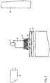
- eine Einrichtung zur computertomographischen Untersuchung eines Probenkörpers in der Seitenansicht, teilweise abgebrochen, wobei der vereinfachte Aufbau eines CT-Röntgengerätes (Computertomographie) schematisch wiedergegeben ist, und wobei als wesentlicher Bestandteil der erfindungsgemäßen Vorrichtung eine Trägeraufnahme zur Abstützung eines Probenträgers, welcher den zu röntgenden Probenkörper trägt, zu erkennen ist; sowie
- Fig. 2
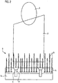
- den Probenkörper samt Probenträger und Trägeraufnahme gemäß
Fig. 1 in einer vergrößerten Darstellung. - Als zu positionierendes Teil wird ein Probenkörper 1 verwendet, der unmittelbar an einem Trägermaterial - im Folgenden auch als Probenträger 2 bezeichnet - festgelegt ist. Für den Probenträger 2 kann bspw. Schaummaterial verwendet werden, vorzugsweise ein geschäumtes, insbesondere säuregehärtetes Phenol- oder Resolharz. Ein derartiger Phenol- oder Resolharz-Schaum hat den Vorteil, dass er sich durch leichtes Eindrücken verformt und dadurch mit handelsüblichen Werkzeugen, z. B. einer Spachtel, Tapetenmesser, also relativ stumpfen Werkzeugen, leicht bearbeitet werden kann. Desweiteren wird durch Eindrücken des zu messenden Teiles, eine sichere und dennoch flexible, d.h. leicht veränderbare Fixierung erreicht.
- Um das ggf. vorgearbeitete Material des Probenträgers 2 seinerseits zu stabilisieren bzw. ortsfest zu fixieren, dient eine erfindungsgemäße Trägeraufnahme 3.
- Diese umfaßt ein plattenförmiges Basisteil 4, die unterschiedliche Größen, Formen und Farben aufweisen kann; bevorzugt wird eine kreisrunde Umfangsform mit einem
- Durchmesser von ca. 1 cm bis ca. 70 cm, bspw. aber auch eine quadratische Umfangsform mit einer Kantenlänge von ca. 1 cm bis ca. 70 cm. Die Stärke eines solchen plattenförmigen Basisteils 4 liegt vorzugsweise in einem Bereich von ca. 2 mm bis ca. 70 mm. Zusätzlich zu einem mindestens bereichsweise organischen Material besteht das Basisteil 4 bevorzugt aus einem metallischen Material oder aus einem Kunststoff, insbesondere Kunstharz od. dgl. Die Unterseite sollte eben und/oder glatt sein. Bevorzugt - insbesondere bei entsprechenden Vorgaben durch den Hersteller einer Prüf-, Kontroll-, Meß- oder Untersuchungseinrichtung - ist das Basisteil aus einem magnetischen oder magnetisierbaren Material hergestellt und ist nach der Erfindung immer mit Magneten (Permanent- und/oder Elektromagneten) versehen, so dass es auf einer ebenfalls magnetischen oder magnetisierbaren Unterlage verschoben/fixiert werden kann. Andererseits ist es auch möglich, das Basisteil nicht magnetisch auszuführen. Von diesem Basisteil 4 ragen etwa lotrecht zu ihrer Grundebene mehrere Dorne 5 weg, die vorzugsweise an ihrem freien Ende in je eine Spitze, Kante od. dgl. Verjüngung münden. Diese Dorne 5 können bspw. die Gestalt von spitzen oder konischen Dornen oder abgeschrägten Stiften oder Nägeln aufweisen. Die Dorne 5 können aus unterschiedlichsten Materialien bestehen und unterschiedliche Formen aufweisen, mit Längen von ca. 5 mm bis ca. 200 mm und Durchmessern von ca. 0,5 mm bis 20 mm. Obwohl die Dorne 5 gleich lang oder aus mehreren Größen gemischt sein können, werden im Allgemeinen Dorne 5 mit unterschiedlichen Längen bevorzugt, bspw. zwei oder drei Arten von Dornen 5, bspw. Dorne 5 mit Längen von 20 mm einerseits und Dorne 5 mit Längen von 40 mm andererseits, so dass deren sämtliche Spitzen nicht innerhalb einer gemeinsamen Ebene liegen.
- Die Dorne 5 sind mit dem plattenförmigen Basisteil 4 fest verbunden. Dies kann evtl. durch Schrauben erfolgen. Bevorzugt werden die Dorne 5 jedoch in das plattenförmige Basisteil 4 oder in eine an dieser festlegbaren Platte eingegossen, bspw. mittels eines Kunstharzes, insbesondere Gießharzes. Es ist auch denkbar, die Dorne 5 durch eine (Loch-) Schablone zu positionieren und anschließend zu umgießen, dabei läßt sich erreichen, dass alle Dorne 5 in einem exakten Raster liegen. Eine andere Art der Befestigung insbesondere nagelförmiger Dorne mit einem verbreiterten Kopf kann dadurch bewirkt werden, dass diese durch eine Lochplatte hindurchgesteckt werden, bis ihre Kopfunterseiten an der Unterseite der Lochplatte anliegen, und sodann von einer weiteren Platte untergriffen werden, die unter der Lochplatte montiert wird, bspw. angeschraubt, derart, dass die Köpfe sich zwischen beiden Platten befinden. Es ist auch noch denkbar, die Dorne 5 und das Basisteil 4 in einem Stück zu gießen oder zu spritzen.
- Die Trägeraufnahme 3 kann durch eingeformte Magnete oder durch Bohrungen 6 für die Aufnahme von Schrauben 7 mit einer Grundplatte 8 verbunden werden, und diese wiederum kann auf einem Adapter 9 montiert werden, der schließlich auf einem Drehtisch 10 od. dgl. platziert wird, oder die Trägeraufnahme 3 wird direkt mit einem (herstellerseitig) vorgegebenen Adapter 9 verbunden, bspw. integriert; auch kann die Trägeraufnahme 3 direkt mit einem Drehtisch 10 od. dgl. verbunden werden. Das hier genannte Verbinden kann dabei durch Fügen, also durch Schrauben-, Stift-, Welle-Naben- und Pressverbindungen, sowie durch Kleben, Löt- und/oder Schweißverbindungen sowie ggf. auch magnetisch erfolgen.
- Nach vollständiger Positionierung des Probenkörpers 1 kann dieser mittels des CT-Röntgengerätes (Computertomographie), bestehend aus einer Röhre 11 und einem Detektor 12, oder einer anderen, vorzugsweise berührungslos messenden Untersuchungseinrichtung gescannt werden.
- Neben Berührungslosen Untersuchungen eignet sich die Erfindungsgemäße Vorrichtung auch für anderweitige Positionierungen, bspw. bei Kontur- und Oberflächenmessverfahren, denn hier wirken nur geringe Kräfte auf die aufgenommen Teile.
- Auch zwecks optischer Betrachtung mit einem Mikroskop, insbesondere mit einem Binokular, wobei der Gegenstand im Auflicht betrachtet wird, oder auch nur als Stativ, eignet sich die Vorrichtung.
Claims (14)
- Vorrichtung zur variablen Positionierung eines Probenträgers (2), mit einer Trägeraufnahme (3) zur Abstützung des Probenträgers (2), dadurch gekennzeichnet, dass die Trägeraufnahme (3)a) ein Basisteil (4) aufweist, das zumindest bereichsweise aus einem organischen Material besteht und mit Magneten versehen ist, so dass es auf einer ebenfalls magnetischen oder magnetisierbaren Unterlage verschiebbar und fixierbar ist; sowieb) eine Mehrzahl von Dornen (5) zum Aufstecken des Probenträgers (2), welche sich von dem Basisteil (4), mit dem sie fest verbunden und insbesondere in welchem sie teilweise eingebettet sind, in einem Raster weg erstrecken und einseitig frei enden.
- Vorrichtung nach Anspruch 1, dadurch gekennzeichnet, dass das Basisteil (4) auf einer Grund- oder Montageplatte oder auf einem Drehtisch oder einem Adapter oder direkt in der Prüf-, Kontroll-, Mess- und/oder Untersuchungseinrichtung magnetisch montierbar ist.
- Vorrichtung nach Anspruch 1 oder 2, dadurch gekennzeichnet, dass das Basisteil (4) eine ebene Unterseite aufweist, die vorzugsweise poliert ist, um ein leichtgängiges Verschieben zu ermöglichen.
- Vorrichtung nach einem der vorhergehenden Ansprüche, dadurch gekennzeichnet, dass das Basisteil (4) eine kreisscheibenförmige Gestalt aufweist, bspw. mit einem Durchmesser von 1 cm oder mehr, vorzugsweise von 2 cm oder mehr, insbesondere von 5 cm oder mehr, und/oder mit einem Durchmesser von 50 cm oder weniger, vorzugsweise von 20 cm oder weniger.
- Vorrichtung nach Anspruch 4, dadurch gekennzeichnet, dass die Höhe des kreisscheibenförmigen Basisteils (4) zwischen 2 mm und 70 mm liegt, vorzugsweise zwischen 3 mm und 50 mm.
- Vorrichtung nach einem der vorhergehenden Ansprüche, dadurch gekennzeichnet, dass das Basisteil (4) eine Grundplatte aus einem anorganischen Material wie bspw. aus Metall oder Stein aufweist.
- Vorrichtung nach einem der vorhergehenden Ansprüche, dadurch gekennzeichnet, dass das Basisteil (4) zumindest bereichsweise aus einem Gießharz besteht.
- Vorrichtung nach einem der vorhergehenden Ansprüche, dadurch gekennzeichnet, dass das Basisteil (4) einen zwei- oder mehrlagigen Aufbau aufweist, wobei sich vorzugsweise oberhalb einer Schicht aus einem anorganischen Material eine Schicht aus einem organischen Material befindet, wobei diese Schichten aus organischem und anorganischem Material insbesondere flächig miteinander verbunden sind, insbesondere dadurch, dass die organische Schicht direkt auf oder an der anorganischen Schicht ausgeformt ist.
- Vorrichtung nach einem der vorhergehenden Ansprüche, dadurch gekennzeichnet, dass die Dorne (5) eine Länge von 70 mm oder weniger aufweisen.
- Vorrichtung nach einem der vorhergehenden Ansprüche, dadurch gekennzeichnet, dass die Dorne (5) unterschiedlich lang ausgeführt sind, so dass deren sämtliche Spitzen nicht innerhalb einer gemeinsamen Ebene liegen und sich die zum Aufstecken erforderliche Druckkraft im Verlauf der Steckbewegung allmählich steigert.
- Vorrichtung nach einem der vorhergehenden Ansprüche, dadurch gekennzeichnet, dass das Basisteil (4) eine vorzugsweise oberseitige Schicht oder Platte aufweist, worin die Dorne (5) eingebettet sind.
- Vorrichtung nach einem der vorhergehenden Ansprüche, dadurch gekennzeichnet, dass die Dorne (5) mit ihren rückwärtigen Enden fest in das Basisteil (4) eingegossen sind, vorzugsweise in Kunststoff, insbesondere in eine Platte aus Kunststoff oder Kunstharz.
- Vorrichtung nach einem der vorhergehenden Ansprüche, dadurch gekennzeichnet, dass die Dornen (5) und das Basisteil (4) durch möglichst gleichzeitiges Gießen oder Spritzen miteinander verbunden sind.
- Verfahren zur variablen Positionierung eines Probenträgers (2), welcher aus einem geschäumten Material besteht, und auf welchem ein zu untersuchendes Teil (1) festgelegt oder festlegbar ist, an einer Prüf-, Kontroll-, Mess- und/oder Untersuchungseinrichtung, mit einer Trägeraufnahme (3) zur Abstützung des Probenträgers (2), dadurch gekennzeichnet, dassa) ein Basisteil (4) der Trägeraufnahme (3), das zumindest bereichsweise aus einem organischen Material besteht und mit Magneten versehen ist, so dass es auf einer magnetischen oder magnetisierbaren Unterlage verschiebbar und fixierbar ist, auf der Prüf-, Kontroll-, Mess- und/oder Untersuchungseinrichtung montiert wird; undb) der Probenträger (2) auf eine Mehrzahl von Dornen (5) der Trägeraufnahme (3), welche sich von dem Basisteil (4), mit dem sie fest verbunden oder in welchem sie teilweise eingebettet sind, in einem Raster weg erstrecken und einseitig frei enden, aufgesteckt wird.
Applications Claiming Priority (1)
| Application Number | Priority Date | Filing Date | Title |
|---|---|---|---|
| DE102011016901 | 2011-04-13 |
Publications (3)
| Publication Number | Publication Date |
|---|---|
| EP2511667A2 EP2511667A2 (de) | 2012-10-17 |
| EP2511667A3 EP2511667A3 (de) | 2014-06-04 |
| EP2511667B1 true EP2511667B1 (de) | 2019-07-31 |
Family
ID=46027524
Family Applications (1)
| Application Number | Title | Priority Date | Filing Date |
|---|---|---|---|
| EP12002625.7A Active EP2511667B1 (de) | 2011-04-13 | 2012-04-13 | Vorrichtung zum Positionieren eines Teils |
Country Status (2)
| Country | Link |
|---|---|
| EP (1) | EP2511667B1 (de) |
| DE (4) | DE102011107753A1 (de) |
Cited By (1)
| Publication number | Priority date | Publication date | Assignee | Title |
|---|---|---|---|---|
| DE102020006104A1 (de) | 2020-10-06 | 2022-04-07 | Veronika Eitel | Halterung für ein zu untersuchendes Objekt |
Families Citing this family (2)
| Publication number | Priority date | Publication date | Assignee | Title |
|---|---|---|---|---|
| DE202014003439U1 (de) | 2013-04-25 | 2014-07-04 | Wolfgang Eitel | Vorrichtung zum Positionieren eines Messobjektes |
| GB202218794D0 (en) * | 2022-12-14 | 2023-01-25 | Rolls Royce Plc | A method of scanning a component |
Citations (1)
| Publication number | Priority date | Publication date | Assignee | Title |
|---|---|---|---|---|
| US20070204500A1 (en) * | 2006-03-03 | 2007-09-06 | Ute Splittgerber | Front-loading display system |
Family Cites Families (3)
| Publication number | Priority date | Publication date | Assignee | Title |
|---|---|---|---|---|
| FR1149040A (fr) * | 1956-06-26 | 1957-12-19 | Procédé et dispositif pour la fabrication d'éléments (corps) absorbant le bruit dans des pièces | |
| JP3927843B2 (ja) * | 2002-03-14 | 2007-06-13 | アロカ株式会社 | マイクロプレート保持装置 |
| DE202008012489U1 (de) * | 2008-09-19 | 2008-12-18 | Fritz Schäfer GmbH | Behälter zur Aufnahme von gleichartigen Gegenständen |
-
2011
- 2011-07-14 DE DE102011107753A patent/DE102011107753A1/de not_active Withdrawn
-
2012
- 2012-04-12 DE DE202012003595U patent/DE202012003595U1/de not_active Expired - Lifetime
- 2012-04-13 DE DE202012003715U patent/DE202012003715U1/de not_active Expired - Lifetime
- 2012-04-13 DE DE102012007313A patent/DE102012007313A1/de not_active Withdrawn
- 2012-04-13 EP EP12002625.7A patent/EP2511667B1/de active Active
Patent Citations (1)
| Publication number | Priority date | Publication date | Assignee | Title |
|---|---|---|---|---|
| US20070204500A1 (en) * | 2006-03-03 | 2007-09-06 | Ute Splittgerber | Front-loading display system |
Non-Patent Citations (2)
| Title |
|---|
| ANONYMOUS: "Manfrotto 143F Fork for Magic Arm 143F B&H Photo Video", 1 January 2010 (2010-01-01), XP055403150, Retrieved from the Internet <URL:https://www.bhphotovideo.com/c/product/5182-REG/Manfrotto_143F_143F_Fork_for_Magic.html> [retrieved on 20170901] * |
| PHUN PHYSICS: "Phun Physics -Demonstrations Home Show Overview Demonstrations Topics Covered Scheduling Info Feedback", 1 January 2000 (2000-01-01), XP055457438, Retrieved from the Internet <URL:https://web.archive.org/web/20010306183806/http://phun.physics.virginia.edu:80/demos/nail_bed.html> [retrieved on 20180307] * |
Cited By (1)
| Publication number | Priority date | Publication date | Assignee | Title |
|---|---|---|---|---|
| DE102020006104A1 (de) | 2020-10-06 | 2022-04-07 | Veronika Eitel | Halterung für ein zu untersuchendes Objekt |
Also Published As
| Publication number | Publication date |
|---|---|
| DE102011107753A1 (de) | 2012-10-18 |
| EP2511667A2 (de) | 2012-10-17 |
| DE202012003715U1 (de) | 2012-05-09 |
| DE202012003595U1 (de) | 2012-05-09 |
| DE102012007313A1 (de) | 2012-10-18 |
| EP2511667A3 (de) | 2014-06-04 |
Similar Documents
| Publication | Publication Date | Title |
|---|---|---|
| EP3122510B1 (de) | Verfahren und vorrichtung zur erhöhung der qualität der schweissnaht beim rührreibschweissen | |
| EP2807002B1 (de) | Schneidwerkzeug | |
| WO2013117540A1 (de) | Rohlingaufnahme für dental-fräsmaschine | |
| DE102007036786A1 (de) | Adapter für eine motorisch angetriebene Werkzeugmaschine mit drehbar anzutreibendem Werkzeug | |
| WO2005002463A1 (de) | Rohling zur herstellung zahntechnischer formteile und verfahren zur herstellung des formteils | |
| DE3702349A1 (de) | Messerschaerfer | |
| EP1068839A2 (de) | Dentalprothesen-Rohling | |
| EP2511667B1 (de) | Vorrichtung zum Positionieren eines Teils | |
| DE3118673C2 (de) | Chirurgisches Schneidwerkzeug für Augenoperationen, sowie Verfahren zur Herstellung des Schneidwerkzeuges | |
| DE202016002602U1 (de) | Polierwerkzeug mit integrierter Polierpaste | |
| DE8631087U1 (de) | Probenhalter | |
| EP3982114A1 (de) | Halterung für ein zu untersuchendes objekt | |
| EP2682239A1 (de) | Manuelles Schneidesystem, seine Verwendung und Verfahren zur Fertigung von OP-Materialien mit Lochausschnitt | |
| DE10037681B4 (de) | Manschette | |
| AT501266B1 (de) | Trenngerät mit gegenläufigen trennelementen | |
| DE102018126749B4 (de) | Probenhaltervorrichtung für eine Schleifeinrichtung und Verfahren zum Herstellen einer mikroskopisch planen Ebene an einer Probe | |
| DE3624343A1 (de) | Verfahren zur herstellung eines faserstreifens und vorrichtung zur durchfuehrung des verfahrens | |
| DE9414447U1 (de) | Befestigungsteil | |
| DE2317362A1 (de) | Lehrenvorrichtung fuer funkenerosionsmaschinen | |
| EP3590854A1 (de) | System aus einem standteller und einer auflage und direktdruckmaschine | |
| EP0543042B1 (de) | Verfahren zur Einstellung der Zungenposition in der Stopfeinheit in einer Bürsten-Herstellungsmaschine und Vorrichtung zur Durchführung des Verfahrens | |
| EP4123286A1 (de) | Ausgiessform für biopsien und verfahren zum herstellen eines gewebeblocks mittels einer solchen ausgiessform | |
| EP3280975B1 (de) | Taststifthalter | |
| EP1741517A1 (de) | Vakuum-Spannvorrichtung zum Fixieren einer Nutzenplatte und entsprechendes Bearbeitungsverfahren | |
| WO2024223744A1 (de) | Kerbtechnik zur vorbereitung eines probenkörpers für eine werkstoffprüfung |
Legal Events
| Date | Code | Title | Description |
|---|---|---|---|
| PUAI | Public reference made under article 153(3) epc to a published international application that has entered the european phase |
Free format text: ORIGINAL CODE: 0009012 |
|
| AK | Designated contracting states |
Kind code of ref document: A2 Designated state(s): AL AT BE BG CH CY CZ DE DK EE ES FI FR GB GR HR HU IE IS IT LI LT LU LV MC MK MT NL NO PL PT RO RS SE SI SK SM TR |
|
| AX | Request for extension of the european patent |
Extension state: BA ME |
|
| PUAL | Search report despatched |
Free format text: ORIGINAL CODE: 0009013 |
|
| AK | Designated contracting states |
Kind code of ref document: A3 Designated state(s): AL AT BE BG CH CY CZ DE DK EE ES FI FR GB GR HR HU IE IS IT LI LT LU LV MC MK MT NL NO PL PT RO RS SE SI SK SM TR |
|
| AX | Request for extension of the european patent |
Extension state: BA ME |
|
| RIC1 | Information provided on ipc code assigned before grant |
Ipc: G01N 23/20 20060101ALI20140430BHEP Ipc: G01D 11/30 20060101AFI20140430BHEP |
|
| 17P | Request for examination filed |
Effective date: 20141204 |
|
| RBV | Designated contracting states (corrected) |
Designated state(s): AL AT BE BG CH CY CZ DE DK EE ES FI FR GB GR HR HU IE IS IT LI LT LU LV MC MK MT NL NO PL PT RO RS SE SI SK SM TR |
|
| RAP3 | Party data changed (applicant data changed or rights of an application transferred) |
Owner name: EITEL, WOLFGANG |
|
| RIN1 | Information on inventor provided before grant (corrected) |
Inventor name: EITEL, WOLFGANG |
|
| 17Q | First examination report despatched |
Effective date: 20150623 |
|
| STAA | Information on the status of an ep patent application or granted ep patent |
Free format text: STATUS: EXAMINATION IS IN PROGRESS |
|
| RAP1 | Party data changed (applicant data changed or rights of an application transferred) |
Owner name: EITEL, WOLFGANG |
|
| RIN1 | Information on inventor provided before grant (corrected) |
Inventor name: EITEL, WOLFGANG |
|
| GRAP | Despatch of communication of intention to grant a patent |
Free format text: ORIGINAL CODE: EPIDOSNIGR1 |
|
| STAA | Information on the status of an ep patent application or granted ep patent |
Free format text: STATUS: GRANT OF PATENT IS INTENDED |
|
| INTG | Intention to grant announced |
Effective date: 20171011 |
|
| GRAJ | Information related to disapproval of communication of intention to grant by the applicant or resumption of examination proceedings by the epo deleted |
Free format text: ORIGINAL CODE: EPIDOSDIGR1 |
|
| STAA | Information on the status of an ep patent application or granted ep patent |
Free format text: STATUS: EXAMINATION IS IN PROGRESS |
|
| INTC | Intention to grant announced (deleted) | ||
| GRAJ | Information related to disapproval of communication of intention to grant by the applicant or resumption of examination proceedings by the epo deleted |
Free format text: ORIGINAL CODE: EPIDOSDIGR1 |
|
| GRAJ | Information related to disapproval of communication of intention to grant by the applicant or resumption of examination proceedings by the epo deleted |
Free format text: ORIGINAL CODE: EPIDOSDIGR1 |
|
| INTC | Intention to grant announced (deleted) | ||
| INTC | Intention to grant announced (deleted) | ||
| GRAJ | Information related to disapproval of communication of intention to grant by the applicant or resumption of examination proceedings by the epo deleted |
Free format text: ORIGINAL CODE: EPIDOSDIGR1 |
|
| GRAP | Despatch of communication of intention to grant a patent |
Free format text: ORIGINAL CODE: EPIDOSNIGR1 |
|
| GRAP | Despatch of communication of intention to grant a patent |
Free format text: ORIGINAL CODE: EPIDOSNIGR1 |
|
| STAA | Information on the status of an ep patent application or granted ep patent |
Free format text: STATUS: GRANT OF PATENT IS INTENDED |
|
| GRAJ | Information related to disapproval of communication of intention to grant by the applicant or resumption of examination proceedings by the epo deleted |
Free format text: ORIGINAL CODE: EPIDOSDIGR1 |
|
| GRAP | Despatch of communication of intention to grant a patent |
Free format text: ORIGINAL CODE: EPIDOSNIGR1 |
|
| INTG | Intention to grant announced |
Effective date: 20181126 |
|
| GRAJ | Information related to disapproval of communication of intention to grant by the applicant or resumption of examination proceedings by the epo deleted |
Free format text: ORIGINAL CODE: EPIDOSDIGR1 |
|
| GRAP | Despatch of communication of intention to grant a patent |
Free format text: ORIGINAL CODE: EPIDOSNIGR1 |
|
| INTG | Intention to grant announced |
Effective date: 20181221 |
|
| INTG | Intention to grant announced |
Effective date: 20190115 |
|
| GRAS | Grant fee paid |
Free format text: ORIGINAL CODE: EPIDOSNIGR3 |
|
| GRAJ | Information related to disapproval of communication of intention to grant by the applicant or resumption of examination proceedings by the epo deleted |
Free format text: ORIGINAL CODE: EPIDOSDIGR1 |
|
| GRAL | Information related to payment of fee for publishing/printing deleted |
Free format text: ORIGINAL CODE: EPIDOSDIGR3 |
|
| STAA | Information on the status of an ep patent application or granted ep patent |
Free format text: STATUS: EXAMINATION IS IN PROGRESS |
|
| GRAP | Despatch of communication of intention to grant a patent |
Free format text: ORIGINAL CODE: EPIDOSNIGR1 |
|
| STAA | Information on the status of an ep patent application or granted ep patent |
Free format text: STATUS: GRANT OF PATENT IS INTENDED |
|
| GRAA | (expected) grant |
Free format text: ORIGINAL CODE: 0009210 |
|
| STAA | Information on the status of an ep patent application or granted ep patent |
Free format text: STATUS: THE PATENT HAS BEEN GRANTED |
|
| INTG | Intention to grant announced |
Effective date: 20190613 |
|
| AK | Designated contracting states |
Kind code of ref document: B1 Designated state(s): AL AT BE BG CH CY CZ DE DK EE ES FI FR GB GR HR HU IE IS IT LI LT LU LV MC MK MT NL NO PL PT RO RS SE SI SK SM TR |
|
| REG | Reference to a national code |
Ref country code: CH Ref legal event code: EP Ref country code: GB Ref legal event code: FG4D Free format text: NOT ENGLISH |
|
| REG | Reference to a national code |
Ref country code: AT Ref legal event code: REF Ref document number: 1161394 Country of ref document: AT Kind code of ref document: T Effective date: 20190815 |
|
| REG | Reference to a national code |
Ref country code: IE Ref legal event code: FG4D Free format text: LANGUAGE OF EP DOCUMENT: GERMAN |
|
| REG | Reference to a national code |
Ref country code: DE Ref legal event code: R096 Ref document number: 502012015070 Country of ref document: DE |
|
| REG | Reference to a national code |
Ref country code: NL Ref legal event code: MP Effective date: 20190731 |
|
| REG | Reference to a national code |
Ref country code: LT Ref legal event code: MG4D |
|
| PG25 | Lapsed in a contracting state [announced via postgrant information from national office to epo] |
Ref country code: BG Free format text: LAPSE BECAUSE OF FAILURE TO SUBMIT A TRANSLATION OF THE DESCRIPTION OR TO PAY THE FEE WITHIN THE PRESCRIBED TIME-LIMIT Effective date: 20191031 Ref country code: NL Free format text: LAPSE BECAUSE OF FAILURE TO SUBMIT A TRANSLATION OF THE DESCRIPTION OR TO PAY THE FEE WITHIN THE PRESCRIBED TIME-LIMIT Effective date: 20190731 Ref country code: SE Free format text: LAPSE BECAUSE OF FAILURE TO SUBMIT A TRANSLATION OF THE DESCRIPTION OR TO PAY THE FEE WITHIN THE PRESCRIBED TIME-LIMIT Effective date: 20190731 Ref country code: HR Free format text: LAPSE BECAUSE OF FAILURE TO SUBMIT A TRANSLATION OF THE DESCRIPTION OR TO PAY THE FEE WITHIN THE PRESCRIBED TIME-LIMIT Effective date: 20190731 Ref country code: LT Free format text: LAPSE BECAUSE OF FAILURE TO SUBMIT A TRANSLATION OF THE DESCRIPTION OR TO PAY THE FEE WITHIN THE PRESCRIBED TIME-LIMIT Effective date: 20190731 Ref country code: PT Free format text: LAPSE BECAUSE OF FAILURE TO SUBMIT A TRANSLATION OF THE DESCRIPTION OR TO PAY THE FEE WITHIN THE PRESCRIBED TIME-LIMIT Effective date: 20191202 Ref country code: FI Free format text: LAPSE BECAUSE OF FAILURE TO SUBMIT A TRANSLATION OF THE DESCRIPTION OR TO PAY THE FEE WITHIN THE PRESCRIBED TIME-LIMIT Effective date: 20190731 Ref country code: NO Free format text: LAPSE BECAUSE OF FAILURE TO SUBMIT A TRANSLATION OF THE DESCRIPTION OR TO PAY THE FEE WITHIN THE PRESCRIBED TIME-LIMIT Effective date: 20191031 |
|
| PG25 | Lapsed in a contracting state [announced via postgrant information from national office to epo] |
Ref country code: LV Free format text: LAPSE BECAUSE OF FAILURE TO SUBMIT A TRANSLATION OF THE DESCRIPTION OR TO PAY THE FEE WITHIN THE PRESCRIBED TIME-LIMIT Effective date: 20190731 Ref country code: GR Free format text: LAPSE BECAUSE OF FAILURE TO SUBMIT A TRANSLATION OF THE DESCRIPTION OR TO PAY THE FEE WITHIN THE PRESCRIBED TIME-LIMIT Effective date: 20191101 Ref country code: ES Free format text: LAPSE BECAUSE OF FAILURE TO SUBMIT A TRANSLATION OF THE DESCRIPTION OR TO PAY THE FEE WITHIN THE PRESCRIBED TIME-LIMIT Effective date: 20190731 Ref country code: RS Free format text: LAPSE BECAUSE OF FAILURE TO SUBMIT A TRANSLATION OF THE DESCRIPTION OR TO PAY THE FEE WITHIN THE PRESCRIBED TIME-LIMIT Effective date: 20190731 Ref country code: IS Free format text: LAPSE BECAUSE OF FAILURE TO SUBMIT A TRANSLATION OF THE DESCRIPTION OR TO PAY THE FEE WITHIN THE PRESCRIBED TIME-LIMIT Effective date: 20191130 Ref country code: AL Free format text: LAPSE BECAUSE OF FAILURE TO SUBMIT A TRANSLATION OF THE DESCRIPTION OR TO PAY THE FEE WITHIN THE PRESCRIBED TIME-LIMIT Effective date: 20190731 |
|
| PG25 | Lapsed in a contracting state [announced via postgrant information from national office to epo] |
Ref country code: TR Free format text: LAPSE BECAUSE OF FAILURE TO SUBMIT A TRANSLATION OF THE DESCRIPTION OR TO PAY THE FEE WITHIN THE PRESCRIBED TIME-LIMIT Effective date: 20190731 |
|
| PG25 | Lapsed in a contracting state [announced via postgrant information from national office to epo] |
Ref country code: DK Free format text: LAPSE BECAUSE OF FAILURE TO SUBMIT A TRANSLATION OF THE DESCRIPTION OR TO PAY THE FEE WITHIN THE PRESCRIBED TIME-LIMIT Effective date: 20190731 Ref country code: EE Free format text: LAPSE BECAUSE OF FAILURE TO SUBMIT A TRANSLATION OF THE DESCRIPTION OR TO PAY THE FEE WITHIN THE PRESCRIBED TIME-LIMIT Effective date: 20190731 Ref country code: RO Free format text: LAPSE BECAUSE OF FAILURE TO SUBMIT A TRANSLATION OF THE DESCRIPTION OR TO PAY THE FEE WITHIN THE PRESCRIBED TIME-LIMIT Effective date: 20190731 Ref country code: IT Free format text: LAPSE BECAUSE OF FAILURE TO SUBMIT A TRANSLATION OF THE DESCRIPTION OR TO PAY THE FEE WITHIN THE PRESCRIBED TIME-LIMIT Effective date: 20190731 Ref country code: PL Free format text: LAPSE BECAUSE OF FAILURE TO SUBMIT A TRANSLATION OF THE DESCRIPTION OR TO PAY THE FEE WITHIN THE PRESCRIBED TIME-LIMIT Effective date: 20190731 |
|
| PG25 | Lapsed in a contracting state [announced via postgrant information from national office to epo] |
Ref country code: IS Free format text: LAPSE BECAUSE OF FAILURE TO SUBMIT A TRANSLATION OF THE DESCRIPTION OR TO PAY THE FEE WITHIN THE PRESCRIBED TIME-LIMIT Effective date: 20200224 Ref country code: SM Free format text: LAPSE BECAUSE OF FAILURE TO SUBMIT A TRANSLATION OF THE DESCRIPTION OR TO PAY THE FEE WITHIN THE PRESCRIBED TIME-LIMIT Effective date: 20190731 Ref country code: SK Free format text: LAPSE BECAUSE OF FAILURE TO SUBMIT A TRANSLATION OF THE DESCRIPTION OR TO PAY THE FEE WITHIN THE PRESCRIBED TIME-LIMIT Effective date: 20190731 Ref country code: CZ Free format text: LAPSE BECAUSE OF FAILURE TO SUBMIT A TRANSLATION OF THE DESCRIPTION OR TO PAY THE FEE WITHIN THE PRESCRIBED TIME-LIMIT Effective date: 20190731 |
|
| REG | Reference to a national code |
Ref country code: DE Ref legal event code: R097 Ref document number: 502012015070 Country of ref document: DE |
|
| PLBE | No opposition filed within time limit |
Free format text: ORIGINAL CODE: 0009261 |
|
| STAA | Information on the status of an ep patent application or granted ep patent |
Free format text: STATUS: NO OPPOSITION FILED WITHIN TIME LIMIT |
|
| PG2D | Information on lapse in contracting state deleted |
Ref country code: IS |
|
| PG25 | Lapsed in a contracting state [announced via postgrant information from national office to epo] |
Ref country code: IS Free format text: LAPSE BECAUSE OF FAILURE TO SUBMIT A TRANSLATION OF THE DESCRIPTION OR TO PAY THE FEE WITHIN THE PRESCRIBED TIME-LIMIT Effective date: 20191030 |
|
| 26N | No opposition filed |
Effective date: 20200603 |
|
| PG25 | Lapsed in a contracting state [announced via postgrant information from national office to epo] |
Ref country code: SI Free format text: LAPSE BECAUSE OF FAILURE TO SUBMIT A TRANSLATION OF THE DESCRIPTION OR TO PAY THE FEE WITHIN THE PRESCRIBED TIME-LIMIT Effective date: 20190731 |
|
| PG25 | Lapsed in a contracting state [announced via postgrant information from national office to epo] |
Ref country code: MC Free format text: LAPSE BECAUSE OF FAILURE TO SUBMIT A TRANSLATION OF THE DESCRIPTION OR TO PAY THE FEE WITHIN THE PRESCRIBED TIME-LIMIT Effective date: 20190731 |
|
| REG | Reference to a national code |
Ref country code: CH Ref legal event code: PL |
|
| PG25 | Lapsed in a contracting state [announced via postgrant information from national office to epo] |
Ref country code: LU Free format text: LAPSE BECAUSE OF NON-PAYMENT OF DUE FEES Effective date: 20200413 Ref country code: CH Free format text: LAPSE BECAUSE OF NON-PAYMENT OF DUE FEES Effective date: 20200430 Ref country code: LI Free format text: LAPSE BECAUSE OF NON-PAYMENT OF DUE FEES Effective date: 20200430 |
|
| REG | Reference to a national code |
Ref country code: BE Ref legal event code: MM Effective date: 20200430 |
|
| PG25 | Lapsed in a contracting state [announced via postgrant information from national office to epo] |
Ref country code: BE Free format text: LAPSE BECAUSE OF NON-PAYMENT OF DUE FEES Effective date: 20200430 |
|
| PG25 | Lapsed in a contracting state [announced via postgrant information from national office to epo] |
Ref country code: IE Free format text: LAPSE BECAUSE OF NON-PAYMENT OF DUE FEES Effective date: 20200413 |
|
| PGFP | Annual fee paid to national office [announced via postgrant information from national office to epo] |
Ref country code: FR Payment date: 20210625 Year of fee payment: 10 |
|
| PGFP | Annual fee paid to national office [announced via postgrant information from national office to epo] |
Ref country code: AT Payment date: 20210625 Year of fee payment: 10 |
|
| PG25 | Lapsed in a contracting state [announced via postgrant information from national office to epo] |
Ref country code: MT Free format text: LAPSE BECAUSE OF FAILURE TO SUBMIT A TRANSLATION OF THE DESCRIPTION OR TO PAY THE FEE WITHIN THE PRESCRIBED TIME-LIMIT Effective date: 20190731 Ref country code: CY Free format text: LAPSE BECAUSE OF FAILURE TO SUBMIT A TRANSLATION OF THE DESCRIPTION OR TO PAY THE FEE WITHIN THE PRESCRIBED TIME-LIMIT Effective date: 20190731 |
|
| PG25 | Lapsed in a contracting state [announced via postgrant information from national office to epo] |
Ref country code: MK Free format text: LAPSE BECAUSE OF FAILURE TO SUBMIT A TRANSLATION OF THE DESCRIPTION OR TO PAY THE FEE WITHIN THE PRESCRIBED TIME-LIMIT Effective date: 20190731 |
|
| REG | Reference to a national code |
Ref country code: AT Ref legal event code: MM01 Ref document number: 1161394 Country of ref document: AT Kind code of ref document: T Effective date: 20220413 |
|
| PG25 | Lapsed in a contracting state [announced via postgrant information from national office to epo] |
Ref country code: FR Free format text: LAPSE BECAUSE OF NON-PAYMENT OF DUE FEES Effective date: 20220430 Ref country code: AT Free format text: LAPSE BECAUSE OF NON-PAYMENT OF DUE FEES Effective date: 20220413 |
|
| P01 | Opt-out of the competence of the unified patent court (upc) registered |
Effective date: 20230601 |
|
| REG | Reference to a national code |
Ref country code: DE Ref legal event code: R081 Ref document number: 502012015070 Country of ref document: DE Owner name: EITEL, WOLFGANG, DE Free format text: FORMER OWNER: EITEL, WOLFGANG, 96103 HALLSTADT, DE |
|
| PGFP | Annual fee paid to national office [announced via postgrant information from national office to epo] |
Ref country code: DE Payment date: 20250430 Year of fee payment: 14 |
|
| PGFP | Annual fee paid to national office [announced via postgrant information from national office to epo] |
Ref country code: GB Payment date: 20250430 Year of fee payment: 14 |