EP2512082A1 - Séparation de la dérive de la fréquence du décalage Doppler dans des systèmes multiporteuse - Google Patents
Séparation de la dérive de la fréquence du décalage Doppler dans des systèmes multiporteuse Download PDFInfo
- Publication number
- EP2512082A1 EP2512082A1 EP11162209A EP11162209A EP2512082A1 EP 2512082 A1 EP2512082 A1 EP 2512082A1 EP 11162209 A EP11162209 A EP 11162209A EP 11162209 A EP11162209 A EP 11162209A EP 2512082 A1 EP2512082 A1 EP 2512082A1
- Authority
- EP
- European Patent Office
- Prior art keywords
- receiver
- finger
- carrier
- frequency
- estimate
- Prior art date
- Legal status (The legal status is an assumption and is not a legal conclusion. Google has not performed a legal analysis and makes no representation as to the accuracy of the status listed.)
- Granted
Links
- 238000000926 separation method Methods 0.000 title 1
- 230000000694 effects Effects 0.000 claims abstract description 35
- 230000001934 delay Effects 0.000 claims abstract description 16
- 238000000034 method Methods 0.000 claims description 31
- 230000008859 change Effects 0.000 claims description 11
- 230000008030 elimination Effects 0.000 claims description 7
- 238000003379 elimination reaction Methods 0.000 claims description 7
- 238000012935 Averaging Methods 0.000 claims description 5
- 238000004590 computer program Methods 0.000 claims description 3
- 239000000969 carrier Substances 0.000 description 25
- 238000001914 filtration Methods 0.000 description 8
- 238000012937 correction Methods 0.000 description 5
- 238000004891 communication Methods 0.000 description 4
- 238000004458 analytical method Methods 0.000 description 3
- 230000009977 dual effect Effects 0.000 description 3
- 238000012545 processing Methods 0.000 description 3
- 230000004044 response Effects 0.000 description 3
- 230000008901 benefit Effects 0.000 description 2
- 230000003247 decreasing effect Effects 0.000 description 2
- 238000004519 manufacturing process Methods 0.000 description 2
- 238000005259 measurement Methods 0.000 description 2
- 238000013459 approach Methods 0.000 description 1
- 238000006243 chemical reaction Methods 0.000 description 1
- 230000001268 conjugating effect Effects 0.000 description 1
- 230000003111 delayed effect Effects 0.000 description 1
- 239000011159 matrix material Substances 0.000 description 1
- 238000005070 sampling Methods 0.000 description 1
- 230000011664 signaling Effects 0.000 description 1
- 230000007480 spreading Effects 0.000 description 1
Images

Classifications
-
- H—ELECTRICITY
- H04—ELECTRIC COMMUNICATION TECHNIQUE
- H04L—TRANSMISSION OF DIGITAL INFORMATION, e.g. TELEGRAPHIC COMMUNICATION
- H04L27/00—Modulated-carrier systems
- H04L27/26—Systems using multi-frequency codes
- H04L27/2601—Multicarrier modulation systems
- H04L27/2647—Arrangements specific to the receiver only
- H04L27/2655—Synchronisation arrangements
- H04L27/2657—Carrier synchronisation
-
- H—ELECTRICITY
- H04—ELECTRIC COMMUNICATION TECHNIQUE
- H04B—TRANSMISSION
- H04B1/00—Details of transmission systems, not covered by a single one of groups H04B3/00 - H04B13/00; Details of transmission systems not characterised by the medium used for transmission
- H04B1/06—Receivers
- H04B1/10—Means associated with receiver for limiting or suppressing noise or interference
- H04B1/1081—Reduction of multipath noise
-
- H—ELECTRICITY
- H04—ELECTRIC COMMUNICATION TECHNIQUE
- H04L—TRANSMISSION OF DIGITAL INFORMATION, e.g. TELEGRAPHIC COMMUNICATION
- H04L25/00—Baseband systems
- H04L25/02—Details ; arrangements for supplying electrical power along data transmission lines
- H04L25/0202—Channel estimation
- H04L25/0222—Estimation of channel variability, e.g. coherence bandwidth, coherence time, fading frequency
-
- H—ELECTRICITY
- H04—ELECTRIC COMMUNICATION TECHNIQUE
- H04L—TRANSMISSION OF DIGITAL INFORMATION, e.g. TELEGRAPHIC COMMUNICATION
- H04L27/00—Modulated-carrier systems
- H04L27/0014—Carrier regulation
-
- H—ELECTRICITY
- H04—ELECTRIC COMMUNICATION TECHNIQUE
- H04L—TRANSMISSION OF DIGITAL INFORMATION, e.g. TELEGRAPHIC COMMUNICATION
- H04L27/00—Modulated-carrier systems
- H04L27/26—Systems using multi-frequency codes
- H04L27/2601—Multicarrier modulation systems
- H04L27/2647—Arrangements specific to the receiver only
- H04L27/2655—Synchronisation arrangements
- H04L27/2668—Details of algorithms
- H04L27/2669—Details of algorithms characterised by the domain of operation
- H04L27/2672—Frequency domain
-
- H—ELECTRICITY
- H04—ELECTRIC COMMUNICATION TECHNIQUE
- H04L—TRANSMISSION OF DIGITAL INFORMATION, e.g. TELEGRAPHIC COMMUNICATION
- H04L27/00—Modulated-carrier systems
- H04L27/26—Systems using multi-frequency codes
- H04L27/2601—Multicarrier modulation systems
- H04L27/2647—Arrangements specific to the receiver only
- H04L27/2655—Synchronisation arrangements
- H04L27/2668—Details of algorithms
- H04L27/2673—Details of algorithms characterised by synchronisation parameters
- H04L27/2675—Pilot or known symbols
-
- H—ELECTRICITY
- H04—ELECTRIC COMMUNICATION TECHNIQUE
- H04L—TRANSMISSION OF DIGITAL INFORMATION, e.g. TELEGRAPHIC COMMUNICATION
- H04L27/00—Modulated-carrier systems
- H04L27/26—Systems using multi-frequency codes
- H04L27/2601—Multicarrier modulation systems
- H04L27/2647—Arrangements specific to the receiver only
- H04L27/2655—Synchronisation arrangements
- H04L27/2689—Link with other circuits, i.e. special connections between synchronisation arrangements and other circuits for achieving synchronisation
- H04L27/2695—Link with other circuits, i.e. special connections between synchronisation arrangements and other circuits for achieving synchronisation with channel estimation, e.g. determination of delay spread, derivative or peak tracking
Definitions
- the invention relates to determining frequency drift and frequency errors caused by Doppler effect in a multi-carrier receiver using at least two fingers.
- AFC Automatic Frequency Correction
- the frequency error is normally composed of two parts; i.e. the frequency error due to the clock mismatches between the user equipment and the base station, which is also called frequency drift, and the random component due to Doppler effect.
- the first is slowly varying mainly because of temperature changes in the user equipment and the latter is a result of several impinging waves received at the user equipment.
- the angle of arrival and the speed which the user equipment travels determine the frequency shift for each wave.
- the Doppler frequency can be estimated using multiple techniques none of which are very accurate or fast. Some of the well known estimation techniques include (but are not limited to), Level Crossing Rate (LCR), Zero Crossing Rate (ZCR) and Covariance-based estimators that exploit autocovariances of powers of the signal envelope.
- LCR Level Crossing Rate
- ZCR Zero Crossing Rate
- Covariance-based estimators that exploit autocovariances of powers of the signal envelope.
- the existing solutions use time domain characteristics like level crossing rate, which requires an appreciable measurement time and thus cannot react to fast Doppler changes.
- the Doppler frequency estimated is inherently noisy and thus needs to be used with some kind of filtering or hysteresis. This causes problems when there are frequent speed changes and the Doppler frequency estimation never converges.
- the current algorithms do not exploit the diversity in dual Cell High-Speed Downlink Packet Access (HSDPA) scenarios.
- HSDPA High-Speed Downlink Packet Access
- the Doppler component is adding noise to the frequency estimation. This leads to decreased accuracy in the frequency error estimation and requires strong filtering. Current Doppler frequency estimation techniques are very inaccurate and require a large number of samples and filtering to converge. In wideband systems where it is possible to resolve independent paths the present solutions cannot be used to estimate and compensate for the Doppler effect per path, i.e. per finger.
- Multi-carrier operation involves jointly scheduling two or more HS carriers to increase the peak data rates per user and increase the utilization of available frequency resources by multiplexing carriers in CELL DCH state.
- Dual-carrier HSDPA is included in Release 8 of 3GPP, other variations such as Dual Band HSDPA, DC-HSDPA etc are included in Release 9.
- Release 10 includes 4 HS carriers and Release 11 is expected to include 8 HS carriers in two different bands.
- Dual-Carrier (or Multi-Carrier) HSDPA there are two types of carriers.
- the first carrier known as the 'Anchor carrier' carries all the legacy physical channels including DPCH/F-DPCH, E-HICH, E-RGCH, E-AGCH, PICH, SCCPCH, AICH etc.
- the other carriers are 'supplementary' carriers and carry a reduced set of physical channels in order to reduce signaling overhead.
- a method of frequency tracking and compensation for frequency error due to Doppler effect in a plurality of multi-path signals is shown in US 6 608 858 .
- the Doppler compensation is based on only one carrier.
- Each finger of a RAKE receiver computes a frequency error for that finger, and a weighted average of all these frequency errors is calculated and filtered to provide a control signal for the internal frequency synthesizers.
- This method will not be able to separate the Doppler component and the drift component completely, since after averaging over fingers the error will still contain some sort of weighted average Doppler component, due to the limitation of using only one carrier.
- the object is achieved in a method of receiving digital data symbols sent from a transmitter on at least two carrier frequencies generated from a common clock signal, wherein individual multipath components of a transmitted data symbol are received with individual delays, and wherein received signals are processed by a receiver unit having at least two fingers, the method comprising the steps of determining from successively received symbols successive channel estimates for each finger and each carrier; calculating for each finger and each carrier from a set of successive channel estimates a change in channel estimate; and determining from said change in channel estimate an estimated frequency error for each finger and each carrier.
- the method further comprises the steps of constructing a linear equation system in which each determined frequency error is expressed as a function of a first variable indicative of a frequency drift caused by a clock mismatch between the receiver and the transmitter and a second variable indicative of a frequency error caused by a Doppler effect due to movement of the receiver relative to the transmitter; solving said equation system to provide a solution with estimates of said first and second variables for each finger; determining from said solution an estimate of the frequency drift; and utilizing said estimate of the frequency drift as a feedback signal for adjusting the receiver clock frequency.
- frequency error estimation can be performed per carrier.
- the carrier diversity can be used to improve the Doppler shift estimation.
- the calculated frequency error estimates contain the same drift component and the same number of random Doppler shift components. This assumes that the fingers are placed at the same time offsets for all the carriers.
- the receiver unit having at least two fingers may be e.g. a RAKE receiver, a GRAKE receiver or an FFT based receiver.
- the step of solving the equation system comprises using Gaussian elimination. Further, the step of solving the equation system may comprise solving a linear least square problem, which is an expedient solution when there are more than two carriers.
- the first variable may be a frequency drift for that finger, and in that case, the method may further comprise the step of determining the estimate of the frequency drift by averaging the first variable over all fingers.
- the second variable is a velocity of the receiver relative to the transmitter for that finger. This has the benefit that these velocities are the same for all carriers, while the frequency error caused by the Doppler effect depends on the carrier frequency.
- the method may further comprise the steps of determining from said solution an estimate of the frequency error caused by the Doppler effect for each finger and each carrier; and utilizing said estimate of the frequency error caused by the Doppler effect for each finger and each carrier for compensating signals received for each finger and each carrier for the frequency error caused by said Doppler effect. This compensation will improve equalizer performance and thus lead to a higher throughput.
- Some embodiments of the invention also relate to a receiver for digital data symbols sent from a transmitter on at least two carrier frequencies generated from a common clock signal, wherein individual multipath components of a transmitted data symbol are received with individual delays, and wherein received signals are processed by a receiver unit having at least two fingers, the receiver being configured to determine from successively received symbols successive channel estimates for each finger and each carrier; calculate for each finger and each carrier from a set of successive channel estimates a change in channel estimate; and determine from said change in channel estimate an estimated frequency error for each finger and each carrier.
- the receiver is further configured to construct a linear equation system in which each determined frequency error is expressed as a function of a first variable indicative of a frequency drift caused by a clock mismatch between the receiver and the transmitter and a second variable indicative of a frequency error caused by a Doppler effect due to movement of the receiver relative to the transmitter; solve said equation system to provide a solution with estimates of said first and second variables for each finger; determine from said solution an estimate of the frequency drift; and utilize said estimate of the frequency drift as a feedback signal for adjusting the receiver clock frequency.
- Embodiments corresponding to those mentioned above for the method also apply for the receiver.
- Some embodiments of the invention relate to a computer program and a computer readable medium with program code means for performing the method described above.
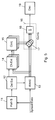
- Figure 1 shows an example of a baseline multi-carrier receiver using one and only one local oscillator.
- the shown receiver uses two antennas and two receiver paths, but it is noted that the invention described below works just as well in receivers with only one receiver path or with more than two receiver paths.
- the receiver uses a number of fingers, such as it is known from e.g. RAKE receivers.
- N carriers are received with two antennas, down-converted to baseband frequency using mixers 101, 201 and a phase locked loop 300 in combination with an oscillator 301, so that DC falls precisely in the middle of the N received carriers.
- the two received signals are then passed through a digital front end (DFE) 102, 202 which involves analog to digital conversion, filtering and automatic gain control operations.
- DFE digital front end
- the carriers are then down converted to zero frequency by using blocks 103,104,105,203,204 and 205. Once the carrier of interest has been down-converted to zero frequency, the adjacent unwanted carrier is removed using a subsequent low-pass filter 106, 107, 108, 206, 207 and 208.
- the output is then passed to the baseband processor block 303 through the Dig RF interface 302.
- the baseband processing block 303 contains functions such as path searcher, finger placer and despreaders, as it will be described below in the case of a RAKE receiver. Instead of the RAKE receiver, e.g. a GRAKE receiver or an FFT based receiver can be used as well.
- the baseband processing block 303 outputs received and despread Common Pilot Channel (CPICH) pilot symbols g i c , a , f , where i denotes the pilot symbol number in the received slot, c denotes carrier number, a denotes receiver antenna number and f denotes the finger number.
- CPICH Common Pilot Channel
- the pilot symbols are fed into an Automatic Frequency Control (AFC) Algorithm block 304.
- AFC Automatic Frequency Control
- the AFC block 304 analyses one slot of received pilot symbols and produces a control command to adjust the PLL in block 300 and reduce the frequency error between the transmitted and received frequencies. As mentioned below, such frequency error may occur due to clock mismatch between the base station and the user equipment and/or a random component due to Doppler effect.
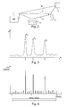
- Figure 2 shows a situation in which a base station 1 and a mobile station 2 of a wireless communications system communicate with each other.
- a signal transmitted from the base station 1 is received by the mobile station 2.
- the transmitted signal travels along multiple paths from the base station to the mobile station.
- there is a direct and unobstructed propagation path 3 but in addition to this direct path, reflections from objects in the surroundings cause a number of indirect paths to exist. Two such paths are shown in the figure.
- One indirect path 4 is reflected from a house 5, while another path 6 is caused by reflection from another building 7.
- the power P received at the mobile station 2 as a function of the time t may look as illustrated in Figure 3 , which shows an example of a power delay profile.
- the power delay profile shows all signals received at the mobile station, including noise and interference signals. However, only the peaks in the power delay profile correspond to the multipath components of the transmitted signal. Together these peaks form the impulse response of the channel.
- the peak P 3 received at the time t 3 corresponds to the direct path 3 in Figure 2
- the peaks P 4 and P 6 received at the times t 4 and t 6 respectively, correspond to the indirect paths 4 and 6 in Figure 2 .
- the delay of the path 6 (corresponding to the peak P 6 ) is larger than the delay of the path 3 (corresponding to the peak P 3 ).
- the mobile station 2 and the base station 1 may be adapted for use in e.g. a Code Division Multiple Access (CDMA) system or a Wideband Code Division Multiple Access (WCDMA) system, and in that case the mobile station 2 may use a RAKE receiver, which is capable of identifying and tracking the various multipath signals for a given channel. In this way the energy or power of several multipath components can be utilized in the receiver.
- each multipath component is assigned a despreader whose reference copy of the spreading code is delayed equally to the path delay of the corresponding multipath component.
- the outputs of the despreaders, i.e. the fingers of the RAKE receiver are then coherently combined to produce a symbol estimate.
- the RAKE receiver requires knowledge of the multipath delays and the values of the channel impulse response for all paths. The signal energy from as many physical paths as possible should be collected. This knowledge can be obtained from the delay profiles.
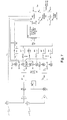
- the received spread data signals are supplied to the path searcher 11 and the RAKE unit 13.
- the path searcher 11 is a device that periodically computes instantaneous impulse response estimates (complex or power) over a range of delays that is also called a path search window. Since the path searcher 11 is mainly used only to detect the existence of paths, its output resolution may be lower than that required by the RAKE unit 13. Thus a general delay estimation algorithm is used in the delay estimator 12, which is able to extract the path positions and find their delays with sufficient accuracy, once they are discovered by the path searcher 11, so that the best ones are selected for despreading in the RAKE unit 13.
- the detected path delays i.e. the delays representing peaks in the delay profile, are then delivered to the RAKE unit 13 and a channel estimator 14.
- the received signals are then despread in the RAKE unit 13, in which each reported delay is assigned a RAKE finger, and each RAKE finger presents a complex despread data symbol.
- each RAKE finger presents a complex despread data symbol.
- three fingers are shown as an example.
- the channel estimator 14 a channel estimate for each path (finger) is calculated from the despread data symbols provided by the RAKE unit 13 and the detected delays provided by the delay estimator 12.
- the complex conjugate of each channel estimate i.e. for each finger
- the combiner 16 the despread data symbols provided by the RAKE unit 13 are multiplied in the multiplying units 17 by the conjugated channel estimates provided by the conjugating unit 15 and summed over all fingers in the summing unit 18. The results are then used for further decoding in the decoder 19.
- received and de-spread Common Pilot Channel (CPICH) pilot symbols g i c , a , f are fed from the baseband processing block 303 (e.g. the RAKE receiver of Figure 5 ) to the AFC block 304, which analyses one slot of received pilot symbols and produces a control command to adjust the PLL in block 300 and reduce the frequency error between the transmitted and received frequencies.
- CPICH Common Pilot Channel
- AFC Automatic Frequency Correction
- the per-slot analysis and generation of frequency correction control command may be performed as follows:
- This frequency error estimate can then be used as a feedback signal or control command to the PLL in block 300, or for generating such a feedback signal.
- the frequency error is normally composed of two parts; i.e. the frequency error or frequency drift due to clock mismatches between the user equipment and the base station and the random component due to Doppler effect.
- the first is slowly varying, mainly because of temperature changes in the user equipment, and the latter is a result of several impinging waves received at the user equipment.
- the angle of arrival and the speed which the user equipment travels determine the frequency shift for each wave.
- the Doppler component is adding noise to the frequency estimation. This leads to decreased accuracy in the frequency error estimation and requires strong filtering. Current Doppler frequency estimation techniques are very inaccurate and require a large number of samples and filtering to converge. In wideband systems where it is possible to resolve independent paths the present solutions cannot be used to estimate and compensate for the Doppler effect per path (finger).
- frequency error estimation can be performed per carrier.
- a multicarrier communication system is here considered as a system where digital data symbols are sent from a transmitter on at least two carrier frequencies, i.e. the two carrier frequencies are transmitted from the same physical location.
- the carrier diversity can be used to improve the Doppler shift estimation.
- all the frequency error estimates i.e. the estimates calculated above, contain the same drift component and the same number of random Doppler shift components. This assumes that the fingers are placed at the same time offsets for all the carriers.
- the carrier wavelength is denoted by ⁇ 0
- ⁇ c is the offset to the wavelength ⁇ 0 for carrier c.
- the unknown Doppler component can be estimated when N > 1, by constructing a linear equation system.
- b k f est , k 1 ⁇ f est , k 2 ... f est , k N T and
- a k 1 - 1 ⁇ 0 + ⁇ ⁇ ⁇ 1 1 - 1 ⁇ 0 + ⁇ ⁇ ⁇ 2 ⁇ ⁇ 1 - 1 ⁇ 0 + ⁇ ⁇ ⁇ N and T is the transpose operation.
- b k is a vector with the frequency error estimates that were measured above and thus considered to be known
- x k is a vector with the variables that we want to determine
- a k is a matrix with the model describing the relationship between them.
- Equation 8 can be solved by e.g. Gaussian elimination.
- Gaussian elimination As mentioned above, if there are more than two carriers, an approximate solution can be found by solving a linear least square problem. However, when there are only two carriers, a least square method is not needed to solve for the drift and Doppler shift components. It will be sufficient to solve equation 6 with normal Gaussian elimination. In other words, in this case there are two unknown variables and two equations, and thus an exact solution can be found without the need for a least square method.
- the solution x k thus provides the wanted values of f drift,k and ⁇ k .
- the estimate f drift calculated in this way can then be used as a feedback signal for the PLL in block 300 instead of previously estimated f est , which leads to a better compensation because the effect of the Doppler is now cancelled.
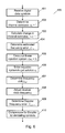
- FIG. 6 shows a flowchart 400 of the method described above.
- digital data symbols including pilot symbols are received in the receiver.
- channel estimates h i c , a , f are determined in step 402, e.g. in a channel estimator 14 as shown in Figure 5 , and in step 403 a change between consecutive channel estimates is calculated.
- the values obtained in step 403 are then used in step 404 for determining a frequency error estimate f est , f c as described above. This estimate represents the total frequency error comprising frequency drift due to clock mismatch as well as frequency error due to Doppler effect.
- Figure 7 shows the receiver of Figure 1 modified by the addition of two extra blocks, i.e. the Doppler frequency estimation unit 305, in which the drift and Doppler components of the frequency error estimates are determined as described above, and the per finger Doppler compensation unit 306, which will be described below.
- the Doppler frequency estimation unit 305 in which the drift and Doppler components of the frequency error estimates are determined as described above, and the per finger Doppler compensation unit 306, which will be described below.
- the improved estimate f drift calculated in Block 305 in figure 7 is fed back to the AFC block 304, where it can then be used as a feedback signal for the PLL in block 300 instead of previously estimated f est as mentioned above.
- the receiver can be further improved by utilizing the determined speed ⁇ k or the corresponding values of the Doppler component of the frequency error, as it will be described below.
- the estimated velocity per finger ( ⁇ k ) can be filtered over a number of consecutive values if the finger position remains fixed.
- the speed estimate per finger can be used to compensate for Doppler effect per finger and carrier.
- the example below describes how this could be done for the HS-PDSCH.
- Let s t c , a , k denote the de-spreaded symbol for the HS-PDSCH for carrier number c , antenna number a and finger number k .
- ⁇ k has been filtered according to (10)
- f doppler , k c - v k ⁇ 0 + ⁇ ⁇ ⁇ c
- This Doppler frequency estimate calculated in block 305 is fed into block 306 in figure 8, and the despreaded data symbols for each finger and carrier may then be compensated for the effect of the Doppler by de-rotating them with the corresponding Doppler frequency error.
- This compensation may be performed e.g. between the RAKE unit 13 and the combiner 17 in Figure 5 , and it is shown in step 410 of Figure 6 .
- the de-rotatation of the symbols will lead to increased performance since less noise is introduced in the combined symbols.
- a weighted average of the Doppler frequency estimate per finger can be used for switching algorithms.
- the value F doppler c can be filtered if desired. Since this method provides more precise Doppler frequency estimates it will improve the mode selection and thus increase the overall system performance.
Landscapes
- Engineering & Computer Science (AREA)
- Computer Networks & Wireless Communication (AREA)
- Signal Processing (AREA)
- Power Engineering (AREA)
- Circuits Of Receivers In General (AREA)
- Mobile Radio Communication Systems (AREA)
Priority Applications (3)
| Application Number | Priority Date | Filing Date | Title |
|---|---|---|---|
| EP11162209.8A EP2512082B1 (fr) | 2011-04-13 | 2011-04-13 | Séparation de la dérive de la fréquence du décalage Doppler dans des systèmes multiporteuse |
| US14/110,875 US9413579B2 (en) | 2011-04-13 | 2012-03-14 | Determining frequency errors in a multi-carrier receiver |
| PCT/EP2012/054486 WO2012139849A1 (fr) | 2011-04-13 | 2012-03-14 | Détermination des erreurs de fréquence dans un récepteur à porteuses multiples |
Applications Claiming Priority (1)
| Application Number | Priority Date | Filing Date | Title |
|---|---|---|---|
| EP11162209.8A EP2512082B1 (fr) | 2011-04-13 | 2011-04-13 | Séparation de la dérive de la fréquence du décalage Doppler dans des systèmes multiporteuse |
Publications (2)
| Publication Number | Publication Date |
|---|---|
| EP2512082A1 true EP2512082A1 (fr) | 2012-10-17 |
| EP2512082B1 EP2512082B1 (fr) | 2013-11-06 |
Family
ID=44544146
Family Applications (1)
| Application Number | Title | Priority Date | Filing Date |
|---|---|---|---|
| EP11162209.8A Not-in-force EP2512082B1 (fr) | 2011-04-13 | 2011-04-13 | Séparation de la dérive de la fréquence du décalage Doppler dans des systèmes multiporteuse |
Country Status (3)
| Country | Link |
|---|---|
| US (1) | US9413579B2 (fr) |
| EP (1) | EP2512082B1 (fr) |
| WO (1) | WO2012139849A1 (fr) |
Cited By (1)
| Publication number | Priority date | Publication date | Assignee | Title |
|---|---|---|---|---|
| CN106559371A (zh) * | 2015-09-24 | 2017-04-05 | 索尼公司 | 用于无线通信的电子设备以及无线通信方法 |
Families Citing this family (6)
| Publication number | Priority date | Publication date | Assignee | Title |
|---|---|---|---|---|
| US9756591B2 (en) * | 2015-03-19 | 2017-09-05 | Telefonaktiebolaget Lm Ericsson (Publ) | Synchronization in the presence of large initial frequency error |
| KR102364688B1 (ko) * | 2015-11-13 | 2022-02-21 | 한국전자통신연구원 | 다중 경로 신호의 파라미터 추정 장치 및 방법 |
| US10871575B2 (en) * | 2018-10-26 | 2020-12-22 | Viasat, Inc. | Multi-mode frequency compensation in mobile terminals |
| DE102020202890B3 (de) * | 2020-03-06 | 2021-07-08 | Continental Automotive Gmbh | Verfahren und Kommunikationsvorrichtung zum Kompensieren von Doppler-Effekten in empfangenen drahtlosen Kommunikationssignalen |
| CN111654338B (zh) * | 2020-05-07 | 2022-07-19 | Oppo广东移动通信有限公司 | 一种多普勒参数估计方法、设备及存储介质 |
| US11671285B1 (en) * | 2022-05-27 | 2023-06-06 | Nanya Technology Corporation | Signal receiving device |
Citations (3)
| Publication number | Priority date | Publication date | Assignee | Title |
|---|---|---|---|---|
| WO2001059937A2 (fr) * | 2000-01-26 | 2001-08-16 | Qualcomm Incorporated | Boucle de poursuite en frequence a ajustage doppler par trajets multiples |
| WO2008099410A2 (fr) * | 2007-02-18 | 2008-08-21 | Runcom Technologies Ltd. | Système et procédé de communication wimax |
| WO2010123783A1 (fr) * | 2009-04-19 | 2010-10-28 | Qualcomm Incorporated | Procédés et systèmes avec une classification d'étalement doppler simplifiée |
Family Cites Families (3)
| Publication number | Priority date | Publication date | Assignee | Title |
|---|---|---|---|---|
| US7443826B1 (en) * | 2000-10-04 | 2008-10-28 | Telefonaktiebolaget L M Ericsson (Publ) | Method and apparatus for automatic frequency control in a CDMA receiver |
| US7257176B2 (en) | 2003-05-15 | 2007-08-14 | Texas Instruments Incorporated | Method of frequency and phase offset estimation using least square method in a burst receiver |
| US7957341B2 (en) | 2005-12-09 | 2011-06-07 | Neocific, Inc. | Frequency correction in a multi-carrier communication system |
-
2011
- 2011-04-13 EP EP11162209.8A patent/EP2512082B1/fr not_active Not-in-force
-
2012
- 2012-03-14 WO PCT/EP2012/054486 patent/WO2012139849A1/fr not_active Ceased
- 2012-03-14 US US14/110,875 patent/US9413579B2/en active Active
Patent Citations (4)
| Publication number | Priority date | Publication date | Assignee | Title |
|---|---|---|---|---|
| WO2001059937A2 (fr) * | 2000-01-26 | 2001-08-16 | Qualcomm Incorporated | Boucle de poursuite en frequence a ajustage doppler par trajets multiples |
| US6608858B1 (en) | 2000-01-26 | 2003-08-19 | Qualcomm Incorporated | Multipath doppler adjusted frequency tracking loop |
| WO2008099410A2 (fr) * | 2007-02-18 | 2008-08-21 | Runcom Technologies Ltd. | Système et procédé de communication wimax |
| WO2010123783A1 (fr) * | 2009-04-19 | 2010-10-28 | Qualcomm Incorporated | Procédés et systèmes avec une classification d'étalement doppler simplifiée |
Cited By (3)
| Publication number | Priority date | Publication date | Assignee | Title |
|---|---|---|---|---|
| CN106559371A (zh) * | 2015-09-24 | 2017-04-05 | 索尼公司 | 用于无线通信的电子设备以及无线通信方法 |
| EP3346655A4 (fr) * | 2015-09-24 | 2019-05-01 | Sony Corporation | Dispositif électronique pour des communications sans fil, et procédé de communications sans fil |
| CN106559371B (zh) * | 2015-09-24 | 2021-01-12 | 索尼公司 | 用于无线通信的电子设备以及无线通信方法 |
Also Published As
| Publication number | Publication date |
|---|---|
| US9413579B2 (en) | 2016-08-09 |
| US20150358192A1 (en) | 2015-12-10 |
| WO2012139849A1 (fr) | 2012-10-18 |
| EP2512082B1 (fr) | 2013-11-06 |
Similar Documents
| Publication | Publication Date | Title |
|---|---|---|
| US7697596B2 (en) | Cluster path processor time alignment for signal suppression/separation in a wireless device | |
| US7209512B2 (en) | CDMA receiver, and searcher in a CDMA receiver | |
| EP2512082B1 (fr) | Séparation de la dérive de la fréquence du décalage Doppler dans des systèmes multiporteuse | |
| US6778591B2 (en) | Path search circuit dividing a received signal into a plurality of FFT windows to reduce arithmetic operation processes for cross-correlation coefficients | |
| US8503509B2 (en) | Method and system for managing, controlling, and combining signals in a frequency selective multipath fading channel | |
| EP2530894B1 (fr) | Procédé et dispositif de mise en uvre de commande automatique de fréquence | |
| KR100347205B1 (ko) | 무선 신호에서 데이터를 복구하는 수신기 및 방법 | |
| US6606487B2 (en) | Automatic frequency correction method and apparatus for time division duplex modes of 3G wireless communications | |
| US20080095141A1 (en) | Cluster Path Processor Multi-Mode Time Alignment Having Expanded Search Window | |
| WO2000033530A1 (fr) | Procede destine a determiner un nombre optimal d'echantillons complexes en vue d'un moyennage coherent dans un systeme de communication | |
| US6256338B1 (en) | Method for determining fading correction factor in a communication system | |
| JPH11252045A (ja) | 干渉除去装置及び干渉除去方法 | |
| JP2000106535A (ja) | 自動周波数制御方法およびシステム | |
| JPH10336072A (ja) | 直接拡散cdma伝送方式におけるrake受信機 | |
| JP4316498B2 (ja) | 無線周波数トラッキングおよび同期捕捉のための装置および方法 | |
| US20030021336A1 (en) | Apparatus and method for measuring SIR in CDMA communication system | |
| US8594257B2 (en) | Method and apparatus for frequency tracking in a space time transmit diversity receiver | |
| US20040156423A1 (en) | Channel gain estimation in a rake receiver using complex weight generation (CWG) algorithms | |
| US7688774B2 (en) | Interference cancellation in radio system receiver | |
| US20040017844A1 (en) | Channel estimation in spread spectrum system | |
| US7889781B2 (en) | Maximum energy delay locked loop for cluster path processing in a wireless device | |
| EP1398889B1 (fr) | Détecteur d'erreur de fréquence et combineur en diversité dans le récepteur d'un système de radiocommunication mobile | |
| JP2000091973A (ja) | Rake合成回路 | |
| US6775341B2 (en) | Time recovery circuit and method for synchronizing timing of a signal in a receiver to timing of the signal in a transmitter | |
| US20090135799A1 (en) | Wireless communications device including path searcher with common coherent correlator and related methods |
Legal Events
| Date | Code | Title | Description |
|---|---|---|---|
| PUAI | Public reference made under article 153(3) epc to a published international application that has entered the european phase |
Free format text: ORIGINAL CODE: 0009012 |
|
| AK | Designated contracting states |
Kind code of ref document: A1 Designated state(s): AL AT BE BG CH CY CZ DE DK EE ES FI FR GB GR HR HU IE IS IT LI LT LU LV MC MK MT NL NO PL PT RO RS SE SI SK SM TR |
|
| AX | Request for extension of the european patent |
Extension state: BA ME |
|
| 17P | Request for examination filed |
Effective date: 20130415 |
|
| GRAP | Despatch of communication of intention to grant a patent |
Free format text: ORIGINAL CODE: EPIDOSNIGR1 |
|
| INTG | Intention to grant announced |
Effective date: 20130523 |
|
| GRAS | Grant fee paid |
Free format text: ORIGINAL CODE: EPIDOSNIGR3 |
|
| GRAA | (expected) grant |
Free format text: ORIGINAL CODE: 0009210 |
|
| AK | Designated contracting states |
Kind code of ref document: B1 Designated state(s): AL AT BE BG CH CY CZ DE DK EE ES FI FR GB GR HR HU IE IS IT LI LT LU LV MC MK MT NL NO PL PT RO RS SE SI SK SM TR |
|
| REG | Reference to a national code |
Ref country code: GB Ref legal event code: FG4D |
|
| REG | Reference to a national code |
Ref country code: CH Ref legal event code: EP |
|
| REG | Reference to a national code |
Ref country code: AT Ref legal event code: REF Ref document number: 640060 Country of ref document: AT Kind code of ref document: T Effective date: 20131215 |
|
| REG | Reference to a national code |
Ref country code: IE Ref legal event code: FG4D |
|
| REG | Reference to a national code |
Ref country code: DE Ref legal event code: R096 Ref document number: 602011003604 Country of ref document: DE Effective date: 20131224 |
|
| REG | Reference to a national code |
Ref country code: NL Ref legal event code: VDEP Effective date: 20131106 |
|
| REG | Reference to a national code |
Ref country code: AT Ref legal event code: MK05 Ref document number: 640060 Country of ref document: AT Kind code of ref document: T Effective date: 20131106 |
|
| REG | Reference to a national code |
Ref country code: LT Ref legal event code: MG4D |
|
| PG25 | Lapsed in a contracting state [announced via postgrant information from national office to epo] |
Ref country code: NL Free format text: LAPSE BECAUSE OF FAILURE TO SUBMIT A TRANSLATION OF THE DESCRIPTION OR TO PAY THE FEE WITHIN THE PRESCRIBED TIME-LIMIT Effective date: 20131106 Ref country code: HR Free format text: LAPSE BECAUSE OF FAILURE TO SUBMIT A TRANSLATION OF THE DESCRIPTION OR TO PAY THE FEE WITHIN THE PRESCRIBED TIME-LIMIT Effective date: 20131106 Ref country code: NO Free format text: LAPSE BECAUSE OF FAILURE TO SUBMIT A TRANSLATION OF THE DESCRIPTION OR TO PAY THE FEE WITHIN THE PRESCRIBED TIME-LIMIT Effective date: 20140206 Ref country code: IS Free format text: LAPSE BECAUSE OF FAILURE TO SUBMIT A TRANSLATION OF THE DESCRIPTION OR TO PAY THE FEE WITHIN THE PRESCRIBED TIME-LIMIT Effective date: 20140306 Ref country code: FI Free format text: LAPSE BECAUSE OF FAILURE TO SUBMIT A TRANSLATION OF THE DESCRIPTION OR TO PAY THE FEE WITHIN THE PRESCRIBED TIME-LIMIT Effective date: 20131106 Ref country code: LT Free format text: LAPSE BECAUSE OF FAILURE TO SUBMIT A TRANSLATION OF THE DESCRIPTION OR TO PAY THE FEE WITHIN THE PRESCRIBED TIME-LIMIT Effective date: 20131106 Ref country code: SE Free format text: LAPSE BECAUSE OF FAILURE TO SUBMIT A TRANSLATION OF THE DESCRIPTION OR TO PAY THE FEE WITHIN THE PRESCRIBED TIME-LIMIT Effective date: 20131106 |
|
| PG25 | Lapsed in a contracting state [announced via postgrant information from national office to epo] |
Ref country code: AT Free format text: LAPSE BECAUSE OF FAILURE TO SUBMIT A TRANSLATION OF THE DESCRIPTION OR TO PAY THE FEE WITHIN THE PRESCRIBED TIME-LIMIT Effective date: 20131106 Ref country code: BE Free format text: LAPSE BECAUSE OF FAILURE TO SUBMIT A TRANSLATION OF THE DESCRIPTION OR TO PAY THE FEE WITHIN THE PRESCRIBED TIME-LIMIT Effective date: 20131106 Ref country code: ES Free format text: LAPSE BECAUSE OF FAILURE TO SUBMIT A TRANSLATION OF THE DESCRIPTION OR TO PAY THE FEE WITHIN THE PRESCRIBED TIME-LIMIT Effective date: 20131106 Ref country code: LV Free format text: LAPSE BECAUSE OF FAILURE TO SUBMIT A TRANSLATION OF THE DESCRIPTION OR TO PAY THE FEE WITHIN THE PRESCRIBED TIME-LIMIT Effective date: 20131106 Ref country code: RS Free format text: LAPSE BECAUSE OF FAILURE TO SUBMIT A TRANSLATION OF THE DESCRIPTION OR TO PAY THE FEE WITHIN THE PRESCRIBED TIME-LIMIT Effective date: 20131106 |
|
| PG25 | Lapsed in a contracting state [announced via postgrant information from national office to epo] |
Ref country code: PT Free format text: LAPSE BECAUSE OF FAILURE TO SUBMIT A TRANSLATION OF THE DESCRIPTION OR TO PAY THE FEE WITHIN THE PRESCRIBED TIME-LIMIT Effective date: 20140306 |
|
| PG25 | Lapsed in a contracting state [announced via postgrant information from national office to epo] |
Ref country code: EE Free format text: LAPSE BECAUSE OF FAILURE TO SUBMIT A TRANSLATION OF THE DESCRIPTION OR TO PAY THE FEE WITHIN THE PRESCRIBED TIME-LIMIT Effective date: 20131106 |
|
| REG | Reference to a national code |
Ref country code: DE Ref legal event code: R097 Ref document number: 602011003604 Country of ref document: DE |
|
| PG25 | Lapsed in a contracting state [announced via postgrant information from national office to epo] |
Ref country code: PL Free format text: LAPSE BECAUSE OF FAILURE TO SUBMIT A TRANSLATION OF THE DESCRIPTION OR TO PAY THE FEE WITHIN THE PRESCRIBED TIME-LIMIT Effective date: 20131106 Ref country code: RO Free format text: LAPSE BECAUSE OF FAILURE TO SUBMIT A TRANSLATION OF THE DESCRIPTION OR TO PAY THE FEE WITHIN THE PRESCRIBED TIME-LIMIT Effective date: 20131106 Ref country code: CZ Free format text: LAPSE BECAUSE OF FAILURE TO SUBMIT A TRANSLATION OF THE DESCRIPTION OR TO PAY THE FEE WITHIN THE PRESCRIBED TIME-LIMIT Effective date: 20131106 Ref country code: SK Free format text: LAPSE BECAUSE OF FAILURE TO SUBMIT A TRANSLATION OF THE DESCRIPTION OR TO PAY THE FEE WITHIN THE PRESCRIBED TIME-LIMIT Effective date: 20131106 Ref country code: IT Free format text: LAPSE BECAUSE OF FAILURE TO SUBMIT A TRANSLATION OF THE DESCRIPTION OR TO PAY THE FEE WITHIN THE PRESCRIBED TIME-LIMIT Effective date: 20131106 |
|
| PLBE | No opposition filed within time limit |
Free format text: ORIGINAL CODE: 0009261 |
|
| STAA | Information on the status of an ep patent application or granted ep patent |
Free format text: STATUS: NO OPPOSITION FILED WITHIN TIME LIMIT |
|
| PG25 | Lapsed in a contracting state [announced via postgrant information from national office to epo] |
Ref country code: DK Free format text: LAPSE BECAUSE OF FAILURE TO SUBMIT A TRANSLATION OF THE DESCRIPTION OR TO PAY THE FEE WITHIN THE PRESCRIBED TIME-LIMIT Effective date: 20131106 |
|
| 26N | No opposition filed |
Effective date: 20140807 |
|
| REG | Reference to a national code |
Ref country code: DE Ref legal event code: R097 Ref document number: 602011003604 Country of ref document: DE Effective date: 20140807 |
|
| PG25 | Lapsed in a contracting state [announced via postgrant information from national office to epo] |
Ref country code: MC Free format text: LAPSE BECAUSE OF FAILURE TO SUBMIT A TRANSLATION OF THE DESCRIPTION OR TO PAY THE FEE WITHIN THE PRESCRIBED TIME-LIMIT Effective date: 20131106 Ref country code: LU Free format text: LAPSE BECAUSE OF FAILURE TO SUBMIT A TRANSLATION OF THE DESCRIPTION OR TO PAY THE FEE WITHIN THE PRESCRIBED TIME-LIMIT Effective date: 20140413 |
|
| REG | Reference to a national code |
Ref country code: CH Ref legal event code: PL |
|
| REG | Reference to a national code |
Ref country code: IE Ref legal event code: MM4A |
|
| PG25 | Lapsed in a contracting state [announced via postgrant information from national office to epo] |
Ref country code: CH Free format text: LAPSE BECAUSE OF NON-PAYMENT OF DUE FEES Effective date: 20140430 Ref country code: LI Free format text: LAPSE BECAUSE OF NON-PAYMENT OF DUE FEES Effective date: 20140430 |
|
| PG25 | Lapsed in a contracting state [announced via postgrant information from national office to epo] |
Ref country code: SI Free format text: LAPSE BECAUSE OF FAILURE TO SUBMIT A TRANSLATION OF THE DESCRIPTION OR TO PAY THE FEE WITHIN THE PRESCRIBED TIME-LIMIT Effective date: 20131106 |
|
| PG25 | Lapsed in a contracting state [announced via postgrant information from national office to epo] |
Ref country code: IE Free format text: LAPSE BECAUSE OF NON-PAYMENT OF DUE FEES Effective date: 20140413 |
|
| PG25 | Lapsed in a contracting state [announced via postgrant information from national office to epo] |
Ref country code: MT Free format text: LAPSE BECAUSE OF FAILURE TO SUBMIT A TRANSLATION OF THE DESCRIPTION OR TO PAY THE FEE WITHIN THE PRESCRIBED TIME-LIMIT Effective date: 20131106 |
|
| REG | Reference to a national code |
Ref country code: FR Ref legal event code: PLFP Year of fee payment: 6 |
|
| PG25 | Lapsed in a contracting state [announced via postgrant information from national office to epo] |
Ref country code: SM Free format text: LAPSE BECAUSE OF FAILURE TO SUBMIT A TRANSLATION OF THE DESCRIPTION OR TO PAY THE FEE WITHIN THE PRESCRIBED TIME-LIMIT Effective date: 20131106 |
|
| PG25 | Lapsed in a contracting state [announced via postgrant information from national office to epo] |
Ref country code: GR Free format text: LAPSE BECAUSE OF FAILURE TO SUBMIT A TRANSLATION OF THE DESCRIPTION OR TO PAY THE FEE WITHIN THE PRESCRIBED TIME-LIMIT Effective date: 20140207 Ref country code: BG Free format text: LAPSE BECAUSE OF FAILURE TO SUBMIT A TRANSLATION OF THE DESCRIPTION OR TO PAY THE FEE WITHIN THE PRESCRIBED TIME-LIMIT Effective date: 20131106 Ref country code: CY Free format text: LAPSE BECAUSE OF FAILURE TO SUBMIT A TRANSLATION OF THE DESCRIPTION OR TO PAY THE FEE WITHIN THE PRESCRIBED TIME-LIMIT Effective date: 20131106 |
|
| PG25 | Lapsed in a contracting state [announced via postgrant information from national office to epo] |
Ref country code: HU Free format text: LAPSE BECAUSE OF FAILURE TO SUBMIT A TRANSLATION OF THE DESCRIPTION OR TO PAY THE FEE WITHIN THE PRESCRIBED TIME-LIMIT; INVALID AB INITIO Effective date: 20110413 Ref country code: TR Free format text: LAPSE BECAUSE OF FAILURE TO SUBMIT A TRANSLATION OF THE DESCRIPTION OR TO PAY THE FEE WITHIN THE PRESCRIBED TIME-LIMIT Effective date: 20131106 |
|
| REG | Reference to a national code |
Ref country code: FR Ref legal event code: PLFP Year of fee payment: 7 |
|
| REG | Reference to a national code |
Ref country code: FR Ref legal event code: PLFP Year of fee payment: 8 |
|
| PG25 | Lapsed in a contracting state [announced via postgrant information from national office to epo] |
Ref country code: MK Free format text: LAPSE BECAUSE OF FAILURE TO SUBMIT A TRANSLATION OF THE DESCRIPTION OR TO PAY THE FEE WITHIN THE PRESCRIBED TIME-LIMIT Effective date: 20131106 |
|
| PG25 | Lapsed in a contracting state [announced via postgrant information from national office to epo] |
Ref country code: AL Free format text: LAPSE BECAUSE OF FAILURE TO SUBMIT A TRANSLATION OF THE DESCRIPTION OR TO PAY THE FEE WITHIN THE PRESCRIBED TIME-LIMIT Effective date: 20131106 |
|
| PGFP | Annual fee paid to national office [announced via postgrant information from national office to epo] |
Ref country code: GB Payment date: 20220427 Year of fee payment: 12 Ref country code: FR Payment date: 20220425 Year of fee payment: 12 Ref country code: DE Payment date: 20220427 Year of fee payment: 12 |
|
| REG | Reference to a national code |
Ref country code: DE Ref legal event code: R119 Ref document number: 602011003604 Country of ref document: DE |
|
| GBPC | Gb: european patent ceased through non-payment of renewal fee |
Effective date: 20230413 |
|
| PG25 | Lapsed in a contracting state [announced via postgrant information from national office to epo] |
Ref country code: GB Free format text: LAPSE BECAUSE OF NON-PAYMENT OF DUE FEES Effective date: 20230413 |
|
| PG25 | Lapsed in a contracting state [announced via postgrant information from national office to epo] |
Ref country code: GB Free format text: LAPSE BECAUSE OF NON-PAYMENT OF DUE FEES Effective date: 20230413 Ref country code: FR Free format text: LAPSE BECAUSE OF NON-PAYMENT OF DUE FEES Effective date: 20230430 Ref country code: DE Free format text: LAPSE BECAUSE OF NON-PAYMENT OF DUE FEES Effective date: 20231103 |