EP2512152A1 - Dispositif auditif avec au moins deux microphones - Google Patents
Dispositif auditif avec au moins deux microphones Download PDFInfo
- Publication number
- EP2512152A1 EP2512152A1 EP11162261A EP11162261A EP2512152A1 EP 2512152 A1 EP2512152 A1 EP 2512152A1 EP 11162261 A EP11162261 A EP 11162261A EP 11162261 A EP11162261 A EP 11162261A EP 2512152 A1 EP2512152 A1 EP 2512152A1
- Authority
- EP
- European Patent Office
- Prior art keywords
- pipe
- chamber
- hearing device
- hearing
- conduit
- Prior art date
- Legal status (The legal status is an assumption and is not a legal conclusion. Google has not performed a legal analysis and makes no representation as to the accuracy of the status listed.)
- Granted
Links
Images

Classifications
-
- H—ELECTRICITY
- H04—ELECTRIC COMMUNICATION TECHNIQUE
- H04R—LOUDSPEAKERS, MICROPHONES, GRAMOPHONE PICK-UPS OR LIKE ACOUSTIC ELECTROMECHANICAL TRANSDUCERS; ELECTRIC HEARING AIDS; PUBLIC ADDRESS SYSTEMS
- H04R25/00—Electric hearing aids
- H04R25/48—Electric hearing aids using constructional means for obtaining a desired frequency response
-
- H—ELECTRICITY
- H04—ELECTRIC COMMUNICATION TECHNIQUE
- H04R—LOUDSPEAKERS, MICROPHONES, GRAMOPHONE PICK-UPS OR LIKE ACOUSTIC ELECTROMECHANICAL TRANSDUCERS; ELECTRIC HEARING AIDS; PUBLIC ADDRESS SYSTEMS
- H04R1/00—Details of transducers, loudspeakers or microphones
- H04R1/20—Arrangements for obtaining desired frequency or directional characteristics
- H04R1/22—Arrangements for obtaining desired frequency or directional characteristics for obtaining desired frequency characteristic only
- H04R1/24—Structural combinations of separate transducers or of two parts of the same transducer and responsive respectively to two or more frequency ranges
- H04R1/245—Structural combinations of separate transducers or of two parts of the same transducer and responsive respectively to two or more frequency ranges of microphones
-
- H—ELECTRICITY
- H04—ELECTRIC COMMUNICATION TECHNIQUE
- H04R—LOUDSPEAKERS, MICROPHONES, GRAMOPHONE PICK-UPS OR LIKE ACOUSTIC ELECTROMECHANICAL TRANSDUCERS; ELECTRIC HEARING AIDS; PUBLIC ADDRESS SYSTEMS
- H04R1/00—Details of transducers, loudspeakers or microphones
- H04R1/02—Casings; Cabinets ; Supports therefor; Mountings therein
- H04R1/04—Structural association of microphone with electric circuitry therefor
-
- H—ELECTRICITY
- H04—ELECTRIC COMMUNICATION TECHNIQUE
- H04R—LOUDSPEAKERS, MICROPHONES, GRAMOPHONE PICK-UPS OR LIKE ACOUSTIC ELECTROMECHANICAL TRANSDUCERS; ELECTRIC HEARING AIDS; PUBLIC ADDRESS SYSTEMS
- H04R1/00—Details of transducers, loudspeakers or microphones
- H04R1/20—Arrangements for obtaining desired frequency or directional characteristics
- H04R1/22—Arrangements for obtaining desired frequency or directional characteristics for obtaining desired frequency characteristic only
- H04R1/28—Transducer mountings or enclosures modified by provision of mechanical or acoustic impedances, e.g. resonator, damping means
- H04R1/2807—Enclosures comprising vibrating or resonating arrangements
-
- H—ELECTRICITY
- H04—ELECTRIC COMMUNICATION TECHNIQUE
- H04R—LOUDSPEAKERS, MICROPHONES, GRAMOPHONE PICK-UPS OR LIKE ACOUSTIC ELECTROMECHANICAL TRANSDUCERS; ELECTRIC HEARING AIDS; PUBLIC ADDRESS SYSTEMS
- H04R1/00—Details of transducers, loudspeakers or microphones
- H04R1/20—Arrangements for obtaining desired frequency or directional characteristics
- H04R1/32—Arrangements for obtaining desired frequency or directional characteristics for obtaining desired directional characteristic only
- H04R1/40—Arrangements for obtaining desired frequency or directional characteristics for obtaining desired directional characteristic only by combining a number of identical transducers
- H04R1/406—Arrangements for obtaining desired frequency or directional characteristics for obtaining desired directional characteristic only by combining a number of identical transducers microphones
-
- H—ELECTRICITY
- H04—ELECTRIC COMMUNICATION TECHNIQUE
- H04R—LOUDSPEAKERS, MICROPHONES, GRAMOPHONE PICK-UPS OR LIKE ACOUSTIC ELECTROMECHANICAL TRANSDUCERS; ELECTRIC HEARING AIDS; PUBLIC ADDRESS SYSTEMS
- H04R25/00—Electric hearing aids
- H04R25/40—Arrangements for obtaining a desired directivity characteristic
- H04R25/402—Arrangements for obtaining a desired directivity characteristic using contructional means
-
- H—ELECTRICITY
- H04—ELECTRIC COMMUNICATION TECHNIQUE
- H04R—LOUDSPEAKERS, MICROPHONES, GRAMOPHONE PICK-UPS OR LIKE ACOUSTIC ELECTROMECHANICAL TRANSDUCERS; ELECTRIC HEARING AIDS; PUBLIC ADDRESS SYSTEMS
- H04R2201/00—Details of transducers, loudspeakers or microphones covered by H04R1/00 but not provided for in any of its subgroups
- H04R2201/40—Details of arrangements for obtaining desired directional characteristic by combining a number of identical transducers covered by H04R1/40 but not provided for in any of its subgroups
- H04R2201/403—Linear arrays of transducers
-
- H—ELECTRICITY
- H04—ELECTRIC COMMUNICATION TECHNIQUE
- H04R—LOUDSPEAKERS, MICROPHONES, GRAMOPHONE PICK-UPS OR LIKE ACOUSTIC ELECTROMECHANICAL TRANSDUCERS; ELECTRIC HEARING AIDS; PUBLIC ADDRESS SYSTEMS
- H04R25/00—Electric hearing aids
- H04R25/40—Arrangements for obtaining a desired directivity characteristic
- H04R25/405—Arrangements for obtaining a desired directivity characteristic by combining a plurality of transducers
-
- H—ELECTRICITY
- H04—ELECTRIC COMMUNICATION TECHNIQUE
- H04R—LOUDSPEAKERS, MICROPHONES, GRAMOPHONE PICK-UPS OR LIKE ACOUSTIC ELECTROMECHANICAL TRANSDUCERS; ELECTRIC HEARING AIDS; PUBLIC ADDRESS SYSTEMS
- H04R29/00—Monitoring arrangements; Testing arrangements
- H04R29/004—Monitoring arrangements; Testing arrangements for microphones
- H04R29/005—Microphone arrays
- H04R29/006—Microphone matching
Definitions
- the present invention relates to a hearing device with two or more microphones. More specifically, the present invention relates to a hearing device such as e.g. a hearing aid or a listening device, which receives acoustic signals from a person's surroundings, modifies the acoustic signals electronically and transmits the modified acoustic signals into the person's ear or ear canal.
- a hearing device such as e.g. a hearing aid or a listening device, which receives acoustic signals from a person's surroundings, modifies the acoustic signals electronically and transmits the modified acoustic signals into the person's ear or ear canal.
- the invention may e.g. be useful in applications such as a hearing aid for compensating a hearing-impaired person's loss of hearing capability or a listening device for augmenting a normal-hearing person's hearing capability.
- European patent EP 1 579 728 B1 discloses a hearing aid with two microphones, wherein output signals from both microphones are combined to provide directional microphone signals.
- US patent 3,458,668 A discloses a hearing aid with two microphones, each with a conduit leading from the microphone to a respective opening in the hearing-aid housing.
- the conduits have different lengths.
- the amplitude of the sound signal reaching a microphone may be changed by changing the length of the respective conduits. In this configuration, the frequency characteristics of the microphones do generally not match each other.
- US patent application 2008/013770 A discloses a microphone array with guide tubes of different lengths each leading from a respective microphone to a respective opening in the housing.
- a damper is placed in the shorter ones of the guide tubes to provide equal sound signal delays between the openings and the microphones. Also in this configuration, the frequency characteristics of the microphones do generally not match each other.
- a “hearing device” refers to a device, such as e.g. a hearing aid or an active ear-protection device, which is configured to improve or augment the hearing capability of an individual by receiving acoustic signals from the individuals' surroundings, modifying the acoustic signals electronically and providing audible signals to at least one of the individual's ears.
- Such audible signals may e.g. be provided in the form of acoustic signals radiated into the individual's outer ears, acoustic signals transferred as mechanical vibrations to the individual's inner ears via the bone structure of the individual's head and/or electric signals transferred to the cochlear nerve of the individual.
- a “hearing system” refers to a system comprising two hearing devices to be worn at or in opposite ears of the individual.
- a “binaural hearing system” refers to a hearing system wherein the two hearing devices are configured to communicate with each other and to coordinate their signal processing.
- Hearing devices, hearing systems and binaural hearing systems may e.g. be used in compensating for a hearing-impaired person's loss of hearing capability or augmenting a normal-hearing person's hearing capability.
- a "transducer” refers to an electroacoustic transducer for converting an acoustic signal into an electric signal, e.g. a microphone.
- the transducer or microphone may function according to any known transducer principle, e.g. electrodynamic, electrostatic or piezoelectric.
- An "active element” of a transducer refers to the element configured to receive the acoustic signal, e.g. a diaphragm.
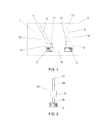
- the hearing device 1 shown in FIG. 1 has a housing 2 comprising a first transducer 3, a second transducer 4, a first chamber 5, a first pipe 6 with a first sound inlet 7, a second chamber 8 and a second pipe 9 with a second sound inlet 10.
- the housing 2 further comprises signal processing means (not shown) configured to process output signals from the transducers 3, 4 and to provide the processed signals to the user of the hearing device in an audible format as is well known in the art.
- signal processing means may include amplifiers, analog-to-digital converters, filters, digital signal processors, digital-to-analog converters, loudspeakers, vibrators etc. as is also well known in the art. Some or all of these may be located outside the housing 2 and still form part of the hearing device 1.
- the first chamber 5 and the first pipe 6 are fluidly connected to form a first conduit 5, 6 leading from the first sound inlet 7 to an active element 11 of the first transducer 3.
- the first conduit 5, 6 is preferably air-tight except at the first sound inlet 7, which penetrates the housing 2 so that acoustic signals from the surroundings may enter the first conduit 5, 6 through the first sound inlet 7 and reach the active element 11 of the first microphone 3 via the first conduit 5, 6.
- the physical dimensions of the first chamber 5 and the first pipe 6 are chosen such that the first conduit 5, 6 forms a first acoustic resonator with the first chamber 5 acting primarily as an acoustic compliance C1 and the first pipe 6 acting primarily as an acoustic mass M1.
- the first chamber 5 is characterised by its volume V1
- the first pipe 6 is characterised by its effective acoustic length L1 and its cross-sectional area S1.
- the second chamber 8 and the second pipe 9 are fluidly connected to form a second conduit 8, 9 leading from the second sound inlet 10 to an active element 12 of the second transducer 4.
- the second conduit 8, 9 is preferably air-tight except at the second sound inlet 10, which penetrates the housing 2 so that acoustic signals from the surroundings may enter the second conduit 8, 9 through the second sound inlet 10 and reach the active element 12 of the second transducer 4 via the second conduit 8, 9.
- the physical dimensions of the second chamber 8 and the second pipe 9 are chosen such that the second conduit 8, 9 forms a second acoustic resonator with the second chamber 8 acting primarily as an acoustic compliance C2 and the second pipe 9 acting primarily as an acoustic mass M2.
- the second chamber 8 is characterised by its volume V2
- the second pipe 9 is characterised by its effective acoustic length L2 and its cross-sectional area S2.
- the first conduit 5, 6 and the first transducer 3 together form a first microphone unit 13.
- the second conduit 8, 9 and the second transducer 4 together form a second microphone unit 14.
- the first and second microphone units 13, 14 together form a microphone system 15.
- M L • ⁇ / S , where:
- the physical dimensions of the chambers 5, 8 and the pipes 6, 9 are chosen such that the frequency of resonance f1 of the first conduit 5, 6 equals the frequency of resonance f2 of the second conduit 8, 9. This ensures that the frequency characteristics of the first and second microphone units 13, 14 are equal, given that the first and second transducers 3, 4 are identical.
- the identity of the frequency characteristics of the first and second microphone units 13, 14 allow the signal processing means to process the transducer output signals to obtain improved directional characteristics of the microphone system 15.
- Configuring the conduits 5, 6, 8, 9 and choosing the physical dimensions of the chambers 5, 8 and the pipes 6, 9 as described above, allows the physical layout of the microphone units 13, 14 to differ substantially, e.g. to have conduits 5, 6, 8, 9 of substantially different lengths. This gives the designer of the hearing device 1 more freedom to place the transducers 3, 4 within the housing 2 without risking a deterioration of the frequency and directional characteristics of the microphone system 15.
- the common frequency of resonance f1, f2 may be chosen to be 20 kHz, which is above the frequency range processed by signal processing means of typical hearing devices, i.e. above 16 kHz, and below the frequency range used by most ultrasonic appliances, i.e. below 25 kHz.
- the frequencies of resonance f1, f2 are located above the frequency range processed by the signal processing means of the hearing device 1, it is prevented that small deviations between the acoustic properties of the conduits 5, 6, 8, 9 affect the audible signals provided to the user of the hearing device 1.
- each conduit 5, 6, 8, 9 functions as a low pass filter with a relatively steep roll-off above the frequency of resonance f1, f2.
- a dedicated quarter-wavelength resonator for dampening of ultrasonic frequencies as disclosed in WO 2004/098232 A1 may thus be omitted.
- the frequencies of resonance f1, f2 above e.g. 10 kHz, 16 kHz or 20 kHz.
- the microphone unit 16 equals the second microphone unit 14 shown in FIG. 1 , except that the pipe 9 comprises a first and a second pipe section 9a, 9b separated from each other and that the chamber 8 is arranged so that it fluidly connects the first and second pipe sections 9a, 9b.
- the transducer 4 is arranged with its active element (not shown) in fluid connection with the second pipe section 9b.
- arranging the chamber 8 at other locations along the pipe 9 does not change the acoustic properties of the conduit 8, 9, 9a, 9b as long as the total length of the pipe 9, i.e. the sum of the lengths of the pipe sections 9a, 9b, remains constant. This provides further freedom for the physical layout of the microphone system 15.
- one or more of the microphone units 13, 14 may be configured as shown in FIG. 3 .
- the microphone unit 17 equals the second microphone unit 14 shown in FIG. 1 , except that a portion of the pipe 9 is replaced by a plurality of pipe branches 9d, 9e, each fluidly connecting a respective branch inlet 10d, 10e in the housing 2 with the chamber 8 via a common pipe section 9c, thus forming a branched pipe 9c, 9d, 9e.
- the common pipe section 9c may be omitted, so that the pipe branches 9d, 9e connect directly to the chamber 8.
- the locations of the branch inlets 10d, 10e may be chosen to allow better reception of acoustical signals for hearing devices 1 located behind the ear of a user, e.g. be on opposite sides of a hearing-device housing 2. Alternatively, the locations may be chosen to provide a non-uniform directional characteristic of the acoustic signals reaching the microphone 4, e.g. on a surface of the housing 2 facing away from the user's head.
- the relative locations of the branch inlets 10d, 10e should preferably be equal or at least similar for each of the microphone units 13, 14, 16, 17 within the microphone system 15 in order to maintain the possibility to provide good directional microphone signals by processing the microphone output signals.
- the microphone system 15 may comprise three or more microphone units 13, 14, 16, 17, in which case the frequency of resonance f1, f2 should preferably be equal for all microphone units 13, 14, 16, 17 within the microphone system 15.
- the microphone system 15 may be used in each of the two hearing devices 1 forming a hearing system or a binaural hearing system.
Landscapes
- Physics & Mathematics (AREA)
- Engineering & Computer Science (AREA)
- Acoustics & Sound (AREA)
- Signal Processing (AREA)
- Health & Medical Sciences (AREA)
- Otolaryngology (AREA)
- General Health & Medical Sciences (AREA)
- Neurosurgery (AREA)
- Circuit For Audible Band Transducer (AREA)
Priority Applications (6)
| Application Number | Priority Date | Filing Date | Title |
|---|---|---|---|
| EP11162261.9A EP2512152B1 (fr) | 2011-04-13 | 2011-04-13 | Dispositif auditif avec au moins deux microphones |
| DK11162261.9T DK2512152T3 (da) | 2011-04-13 | 2011-04-13 | Høreapparat med to eller flere mikrofoner |
| US13/439,642 US8724836B2 (en) | 2011-04-13 | 2012-04-04 | Hearing device with two or more microphones and two or more resonators having different lengths and the same resonant frequency |
| AU2012202148A AU2012202148A1 (en) | 2011-04-13 | 2012-04-13 | Hearing Device With Two or More Microphones |
| CN201210109502.9A CN102740211B (zh) | 2011-04-13 | 2012-04-13 | 具有两个以上传声器的听力装置 |
| US14/224,498 US9185498B2 (en) | 2011-04-13 | 2014-03-25 | Hearing device with two or more microphones and two or more resonators having different lengths and the same resonant frequency |
Applications Claiming Priority (1)
| Application Number | Priority Date | Filing Date | Title |
|---|---|---|---|
| EP11162261.9A EP2512152B1 (fr) | 2011-04-13 | 2011-04-13 | Dispositif auditif avec au moins deux microphones |
Publications (2)
| Publication Number | Publication Date |
|---|---|
| EP2512152A1 true EP2512152A1 (fr) | 2012-10-17 |
| EP2512152B1 EP2512152B1 (fr) | 2013-11-06 |
Family
ID=44343057
Family Applications (1)
| Application Number | Title | Priority Date | Filing Date |
|---|---|---|---|
| EP11162261.9A Active EP2512152B1 (fr) | 2011-04-13 | 2011-04-13 | Dispositif auditif avec au moins deux microphones |
Country Status (5)
| Country | Link |
|---|---|
| US (2) | US8724836B2 (fr) |
| EP (1) | EP2512152B1 (fr) |
| CN (1) | CN102740211B (fr) |
| AU (1) | AU2012202148A1 (fr) |
| DK (1) | DK2512152T3 (fr) |
Families Citing this family (10)
| Publication number | Priority date | Publication date | Assignee | Title |
|---|---|---|---|---|
| CN103856857B (zh) * | 2012-12-06 | 2018-01-05 | 美商富迪科技股份有限公司 | 电子装置 |
| US9084053B2 (en) * | 2013-01-11 | 2015-07-14 | Red Tail Hawk Corporation | Microphone environmental protection device |
| US8958592B2 (en) * | 2013-05-23 | 2015-02-17 | Fortemedia, Inc. | Microphone array housing with acoustic extending structure and electronic device utilizing the same |
| US9439008B2 (en) | 2013-07-16 | 2016-09-06 | iHear Medical, Inc. | Online hearing aid fitting system and methods for non-expert user |
| US20160066822A1 (en) | 2014-09-08 | 2016-03-10 | iHear Medical, Inc. | Hearing test system for non-expert user with built-in calibration and method |
| WO2016044178A1 (fr) * | 2014-09-15 | 2016-03-24 | iHear Medical, Inc. | Dispositif auditif intracanal ayant un canal sonore de mise en forme de spectre de fréquences allongé |
| US10412491B2 (en) * | 2015-10-30 | 2019-09-10 | Goertek, Inc. | Band-pass acoustic filter and acoustic sensing apparatus |
| US20180317025A1 (en) | 2017-03-02 | 2018-11-01 | Sonion Nederland B.V. | A sensor comprising two parallel acoustical filter elements, an assembly comprising a sensor and the filter, a hearable and a method |
| FR3109687B1 (fr) * | 2020-04-23 | 2022-07-29 | Akoustic Arts | Système Acoustique |
| TWI779407B (zh) * | 2020-11-24 | 2022-10-01 | 美律實業股份有限公司 | 電子裝置 |
Citations (7)
| Publication number | Priority date | Publication date | Assignee | Title |
|---|---|---|---|---|
| US3458668A (en) | 1966-12-06 | 1969-07-29 | Willco Horgerate Medizinische | Directional hearing aid |
| US5526430A (en) * | 1994-08-03 | 1996-06-11 | Matsushita Electric Industrial Co., Ltd. | Pressure gradient type microphone apparatus with acoustic terminals provided by acoustic passages |
| EP0742678A2 (fr) * | 1995-05-11 | 1996-11-13 | AT&T Corp. | Microphone à gradient avec suppression de bruit |
| US5848172A (en) * | 1996-11-22 | 1998-12-08 | Lucent Technologies Inc. | Directional microphone |
| WO2004098232A1 (fr) | 2003-04-28 | 2004-11-11 | Oticon A/S | Microphone, appareil de correction auditive dote d'un microphone et structure d'entree pour microphone |
| EP1579728B1 (fr) | 2002-12-20 | 2007-09-19 | Oticon A/S | Systeme de microphone a reponse directionnelle |
| US20080013770A1 (en) | 2006-07-17 | 2008-01-17 | Fortemedia, Inc. | microphone array in housing receiving sound via guide tube |
Family Cites Families (6)
| Publication number | Priority date | Publication date | Assignee | Title |
|---|---|---|---|---|
| DE3224614A1 (de) * | 1982-07-01 | 1984-01-05 | Siemens AG, 1000 Berlin und 8000 München | Elektrisches hoergeraet |
| US7324653B2 (en) | 2002-07-12 | 2008-01-29 | Oticon A/S | Suspension means for transducer |
| DE102005036849A1 (de) | 2005-08-04 | 2007-02-22 | Siemens Audiologische Technik Gmbh | Hörerschlauch mit Dämpfungselement und entsprechende Hörvorrichtung |
| US7899203B2 (en) | 2005-09-15 | 2011-03-01 | Sonion Nederland B.V. | Transducers with improved viscous damping |
| CH699444B1 (de) | 2006-10-11 | 2010-03-15 | Phonak Ag | Hörgerät. |
| DE102007031872B4 (de) | 2007-07-09 | 2009-11-19 | Siemens Audiologische Technik Gmbh | Hörgerät |
-
2011
- 2011-04-13 EP EP11162261.9A patent/EP2512152B1/fr active Active
- 2011-04-13 DK DK11162261.9T patent/DK2512152T3/da active
-
2012
- 2012-04-04 US US13/439,642 patent/US8724836B2/en active Active
- 2012-04-13 AU AU2012202148A patent/AU2012202148A1/en not_active Abandoned
- 2012-04-13 CN CN201210109502.9A patent/CN102740211B/zh active Active
-
2014
- 2014-03-25 US US14/224,498 patent/US9185498B2/en active Active
Patent Citations (7)
| Publication number | Priority date | Publication date | Assignee | Title |
|---|---|---|---|---|
| US3458668A (en) | 1966-12-06 | 1969-07-29 | Willco Horgerate Medizinische | Directional hearing aid |
| US5526430A (en) * | 1994-08-03 | 1996-06-11 | Matsushita Electric Industrial Co., Ltd. | Pressure gradient type microphone apparatus with acoustic terminals provided by acoustic passages |
| EP0742678A2 (fr) * | 1995-05-11 | 1996-11-13 | AT&T Corp. | Microphone à gradient avec suppression de bruit |
| US5848172A (en) * | 1996-11-22 | 1998-12-08 | Lucent Technologies Inc. | Directional microphone |
| EP1579728B1 (fr) | 2002-12-20 | 2007-09-19 | Oticon A/S | Systeme de microphone a reponse directionnelle |
| WO2004098232A1 (fr) | 2003-04-28 | 2004-11-11 | Oticon A/S | Microphone, appareil de correction auditive dote d'un microphone et structure d'entree pour microphone |
| US20080013770A1 (en) | 2006-07-17 | 2008-01-17 | Fortemedia, Inc. | microphone array in housing receiving sound via guide tube |
Also Published As
| Publication number | Publication date |
|---|---|
| EP2512152B1 (fr) | 2013-11-06 |
| CN102740211B (zh) | 2017-06-30 |
| US20120263330A1 (en) | 2012-10-18 |
| DK2512152T3 (da) | 2014-02-03 |
| US20140205121A1 (en) | 2014-07-24 |
| CN102740211A (zh) | 2012-10-17 |
| US9185498B2 (en) | 2015-11-10 |
| US8724836B2 (en) | 2014-05-13 |
| AU2012202148A1 (en) | 2012-11-01 |
Similar Documents
| Publication | Publication Date | Title |
|---|---|---|
| EP2512152B1 (fr) | Dispositif auditif avec au moins deux microphones | |
| EP2405674B1 (fr) | Aide auditive avec réduction de l'occlusion | |
| EP3937508B1 (fr) | Écouteur, dispositif auditif et système pour annulation d'occlusion active | |
| US10375491B2 (en) | Hearing device with a barrier element | |
| US20090238385A1 (en) | Hearing system with partial band signal exchange and corresponding method | |
| EP2217006B1 (fr) | Dispositif auditif | |
| US11425513B2 (en) | Suspension assembly for hearing aid receiver | |
| JP6198765B2 (ja) | 短縮された待ち時間で風雑音を低減した伝送信号を発生する方法 | |
| CN104936106B (zh) | 扬声器系统 | |
| KR100736894B1 (ko) | 다채널 진동판이 구비된 전기-음향 변환장치 및 이를이용한 보청기 | |
| US20230276179A1 (en) | Hearing device for occlusion reduction and components thereof | |
| KR20170142571A (ko) | 불연 피에조 압전 스피커장치 | |
| US20220400335A1 (en) | Hearing device | |
| US3921756A (en) | Acoustic ear mold for hearing aid | |
| US8855350B2 (en) | Patterned implantable electret microphone | |
| US8755551B2 (en) | Hearing apparatus having a special sound channel | |
| US10334356B2 (en) | Microphone for a hearing aid | |
| JP3063750B1 (ja) | 補聴器 | |
| US20080298620A1 (en) | Wearing hook with metal section for a hearing device | |
| EP3570565B1 (fr) | Solution de filtre de cire destinée à un écouteur de prothèse auditive | |
| US10524045B2 (en) | Sound receiver and personal audio system having the same |
Legal Events
| Date | Code | Title | Description |
|---|---|---|---|
| PUAI | Public reference made under article 153(3) epc to a published international application that has entered the european phase |
Free format text: ORIGINAL CODE: 0009012 |
|
| AK | Designated contracting states |
Kind code of ref document: A1 Designated state(s): AL AT BE BG CH CY CZ DE DK EE ES FI FR GB GR HR HU IE IS IT LI LT LU LV MC MK MT NL NO PL PT RO RS SE SI SK SM TR |
|
| AX | Request for extension of the european patent |
Extension state: BA ME |
|
| GRAP | Despatch of communication of intention to grant a patent |
Free format text: ORIGINAL CODE: EPIDOSNIGR1 |
|
| 17P | Request for examination filed |
Effective date: 20130417 |
|
| INTG | Intention to grant announced |
Effective date: 20130528 |
|
| GRAS | Grant fee paid |
Free format text: ORIGINAL CODE: EPIDOSNIGR3 |
|
| GRAA | (expected) grant |
Free format text: ORIGINAL CODE: 0009210 |
|
| AK | Designated contracting states |
Kind code of ref document: B1 Designated state(s): AL AT BE BG CH CY CZ DE DK EE ES FI FR GB GR HR HU IE IS IT LI LT LU LV MC MK MT NL NO PL PT RO RS SE SI SK SM TR |
|
| REG | Reference to a national code |
Ref country code: GB Ref legal event code: FG4D |
|
| REG | Reference to a national code |
Ref country code: CH Ref legal event code: EP |
|
| REG | Reference to a national code |
Ref country code: AT Ref legal event code: REF Ref document number: 640106 Country of ref document: AT Kind code of ref document: T Effective date: 20131215 |
|
| REG | Reference to a national code |
Ref country code: IE Ref legal event code: FG4D |
|
| REG | Reference to a national code |
Ref country code: DE Ref legal event code: R096 Ref document number: 602011003606 Country of ref document: DE Effective date: 20140109 |
|
| REG | Reference to a national code |
Ref country code: DK Ref legal event code: T3 Effective date: 20140130 |
|
| REG | Reference to a national code |
Ref country code: NL Ref legal event code: VDEP Effective date: 20131106 |
|
| REG | Reference to a national code |
Ref country code: AT Ref legal event code: MK05 Ref document number: 640106 Country of ref document: AT Kind code of ref document: T Effective date: 20131106 |
|
| REG | Reference to a national code |
Ref country code: LT Ref legal event code: MG4D |
|
| PG25 | Lapsed in a contracting state [announced via postgrant information from national office to epo] |
Ref country code: FI Free format text: LAPSE BECAUSE OF FAILURE TO SUBMIT A TRANSLATION OF THE DESCRIPTION OR TO PAY THE FEE WITHIN THE PRESCRIBED TIME-LIMIT Effective date: 20131106 Ref country code: NL Free format text: LAPSE BECAUSE OF FAILURE TO SUBMIT A TRANSLATION OF THE DESCRIPTION OR TO PAY THE FEE WITHIN THE PRESCRIBED TIME-LIMIT Effective date: 20131106 Ref country code: IS Free format text: LAPSE BECAUSE OF FAILURE TO SUBMIT A TRANSLATION OF THE DESCRIPTION OR TO PAY THE FEE WITHIN THE PRESCRIBED TIME-LIMIT Effective date: 20140306 Ref country code: NO Free format text: LAPSE BECAUSE OF FAILURE TO SUBMIT A TRANSLATION OF THE DESCRIPTION OR TO PAY THE FEE WITHIN THE PRESCRIBED TIME-LIMIT Effective date: 20140206 Ref country code: SE Free format text: LAPSE BECAUSE OF FAILURE TO SUBMIT A TRANSLATION OF THE DESCRIPTION OR TO PAY THE FEE WITHIN THE PRESCRIBED TIME-LIMIT Effective date: 20131106 Ref country code: LT Free format text: LAPSE BECAUSE OF FAILURE TO SUBMIT A TRANSLATION OF THE DESCRIPTION OR TO PAY THE FEE WITHIN THE PRESCRIBED TIME-LIMIT Effective date: 20131106 Ref country code: HR Free format text: LAPSE BECAUSE OF FAILURE TO SUBMIT A TRANSLATION OF THE DESCRIPTION OR TO PAY THE FEE WITHIN THE PRESCRIBED TIME-LIMIT Effective date: 20131106 |
|
| PG25 | Lapsed in a contracting state [announced via postgrant information from national office to epo] |
Ref country code: ES Free format text: LAPSE BECAUSE OF FAILURE TO SUBMIT A TRANSLATION OF THE DESCRIPTION OR TO PAY THE FEE WITHIN THE PRESCRIBED TIME-LIMIT Effective date: 20131106 Ref country code: RS Free format text: LAPSE BECAUSE OF FAILURE TO SUBMIT A TRANSLATION OF THE DESCRIPTION OR TO PAY THE FEE WITHIN THE PRESCRIBED TIME-LIMIT Effective date: 20131106 Ref country code: LV Free format text: LAPSE BECAUSE OF FAILURE TO SUBMIT A TRANSLATION OF THE DESCRIPTION OR TO PAY THE FEE WITHIN THE PRESCRIBED TIME-LIMIT Effective date: 20131106 Ref country code: BE Free format text: LAPSE BECAUSE OF FAILURE TO SUBMIT A TRANSLATION OF THE DESCRIPTION OR TO PAY THE FEE WITHIN THE PRESCRIBED TIME-LIMIT Effective date: 20131106 Ref country code: AT Free format text: LAPSE BECAUSE OF FAILURE TO SUBMIT A TRANSLATION OF THE DESCRIPTION OR TO PAY THE FEE WITHIN THE PRESCRIBED TIME-LIMIT Effective date: 20131106 |
|
| PG25 | Lapsed in a contracting state [announced via postgrant information from national office to epo] |
Ref country code: PT Free format text: LAPSE BECAUSE OF FAILURE TO SUBMIT A TRANSLATION OF THE DESCRIPTION OR TO PAY THE FEE WITHIN THE PRESCRIBED TIME-LIMIT Effective date: 20140306 |
|
| PG25 | Lapsed in a contracting state [announced via postgrant information from national office to epo] |
Ref country code: EE Free format text: LAPSE BECAUSE OF FAILURE TO SUBMIT A TRANSLATION OF THE DESCRIPTION OR TO PAY THE FEE WITHIN THE PRESCRIBED TIME-LIMIT Effective date: 20131106 |
|
| REG | Reference to a national code |
Ref country code: DE Ref legal event code: R097 Ref document number: 602011003606 Country of ref document: DE |
|
| PG25 | Lapsed in a contracting state [announced via postgrant information from national office to epo] |
Ref country code: PL Free format text: LAPSE BECAUSE OF FAILURE TO SUBMIT A TRANSLATION OF THE DESCRIPTION OR TO PAY THE FEE WITHIN THE PRESCRIBED TIME-LIMIT Effective date: 20131106 Ref country code: IT Free format text: LAPSE BECAUSE OF FAILURE TO SUBMIT A TRANSLATION OF THE DESCRIPTION OR TO PAY THE FEE WITHIN THE PRESCRIBED TIME-LIMIT Effective date: 20131106 Ref country code: CZ Free format text: LAPSE BECAUSE OF FAILURE TO SUBMIT A TRANSLATION OF THE DESCRIPTION OR TO PAY THE FEE WITHIN THE PRESCRIBED TIME-LIMIT Effective date: 20131106 Ref country code: SK Free format text: LAPSE BECAUSE OF FAILURE TO SUBMIT A TRANSLATION OF THE DESCRIPTION OR TO PAY THE FEE WITHIN THE PRESCRIBED TIME-LIMIT Effective date: 20131106 Ref country code: RO Free format text: LAPSE BECAUSE OF FAILURE TO SUBMIT A TRANSLATION OF THE DESCRIPTION OR TO PAY THE FEE WITHIN THE PRESCRIBED TIME-LIMIT Effective date: 20131106 |
|
| PLBE | No opposition filed within time limit |
Free format text: ORIGINAL CODE: 0009261 |
|
| STAA | Information on the status of an ep patent application or granted ep patent |
Free format text: STATUS: NO OPPOSITION FILED WITHIN TIME LIMIT |
|
| 26N | No opposition filed |
Effective date: 20140807 |
|
| REG | Reference to a national code |
Ref country code: DE Ref legal event code: R097 Ref document number: 602011003606 Country of ref document: DE Effective date: 20140807 |
|
| PG25 | Lapsed in a contracting state [announced via postgrant information from national office to epo] |
Ref country code: MC Free format text: LAPSE BECAUSE OF FAILURE TO SUBMIT A TRANSLATION OF THE DESCRIPTION OR TO PAY THE FEE WITHIN THE PRESCRIBED TIME-LIMIT Effective date: 20131106 Ref country code: LU Free format text: LAPSE BECAUSE OF FAILURE TO SUBMIT A TRANSLATION OF THE DESCRIPTION OR TO PAY THE FEE WITHIN THE PRESCRIBED TIME-LIMIT Effective date: 20140413 |
|
| REG | Reference to a national code |
Ref country code: IE Ref legal event code: MM4A |
|
| PG25 | Lapsed in a contracting state [announced via postgrant information from national office to epo] |
Ref country code: SI Free format text: LAPSE BECAUSE OF FAILURE TO SUBMIT A TRANSLATION OF THE DESCRIPTION OR TO PAY THE FEE WITHIN THE PRESCRIBED TIME-LIMIT Effective date: 20131106 |
|
| PG25 | Lapsed in a contracting state [announced via postgrant information from national office to epo] |
Ref country code: IE Free format text: LAPSE BECAUSE OF NON-PAYMENT OF DUE FEES Effective date: 20140413 |
|
| PG25 | Lapsed in a contracting state [announced via postgrant information from national office to epo] |
Ref country code: MT Free format text: LAPSE BECAUSE OF FAILURE TO SUBMIT A TRANSLATION OF THE DESCRIPTION OR TO PAY THE FEE WITHIN THE PRESCRIBED TIME-LIMIT Effective date: 20131106 |
|
| REG | Reference to a national code |
Ref country code: FR Ref legal event code: PLFP Year of fee payment: 6 |
|
| PG25 | Lapsed in a contracting state [announced via postgrant information from national office to epo] |
Ref country code: SM Free format text: LAPSE BECAUSE OF FAILURE TO SUBMIT A TRANSLATION OF THE DESCRIPTION OR TO PAY THE FEE WITHIN THE PRESCRIBED TIME-LIMIT Effective date: 20131106 |
|
| PG25 | Lapsed in a contracting state [announced via postgrant information from national office to epo] |
Ref country code: BG Free format text: LAPSE BECAUSE OF FAILURE TO SUBMIT A TRANSLATION OF THE DESCRIPTION OR TO PAY THE FEE WITHIN THE PRESCRIBED TIME-LIMIT Effective date: 20131106 Ref country code: GR Free format text: LAPSE BECAUSE OF FAILURE TO SUBMIT A TRANSLATION OF THE DESCRIPTION OR TO PAY THE FEE WITHIN THE PRESCRIBED TIME-LIMIT Effective date: 20140207 Ref country code: CY Free format text: LAPSE BECAUSE OF FAILURE TO SUBMIT A TRANSLATION OF THE DESCRIPTION OR TO PAY THE FEE WITHIN THE PRESCRIBED TIME-LIMIT Effective date: 20131106 |
|
| PG25 | Lapsed in a contracting state [announced via postgrant information from national office to epo] |
Ref country code: TR Free format text: LAPSE BECAUSE OF FAILURE TO SUBMIT A TRANSLATION OF THE DESCRIPTION OR TO PAY THE FEE WITHIN THE PRESCRIBED TIME-LIMIT Effective date: 20131106 Ref country code: HU Free format text: LAPSE BECAUSE OF FAILURE TO SUBMIT A TRANSLATION OF THE DESCRIPTION OR TO PAY THE FEE WITHIN THE PRESCRIBED TIME-LIMIT; INVALID AB INITIO Effective date: 20110413 |
|
| REG | Reference to a national code |
Ref country code: FR Ref legal event code: PLFP Year of fee payment: 7 |
|
| REG | Reference to a national code |
Ref country code: FR Ref legal event code: PLFP Year of fee payment: 8 |
|
| PG25 | Lapsed in a contracting state [announced via postgrant information from national office to epo] |
Ref country code: MK Free format text: LAPSE BECAUSE OF FAILURE TO SUBMIT A TRANSLATION OF THE DESCRIPTION OR TO PAY THE FEE WITHIN THE PRESCRIBED TIME-LIMIT Effective date: 20131106 |
|
| PG25 | Lapsed in a contracting state [announced via postgrant information from national office to epo] |
Ref country code: AL Free format text: LAPSE BECAUSE OF FAILURE TO SUBMIT A TRANSLATION OF THE DESCRIPTION OR TO PAY THE FEE WITHIN THE PRESCRIBED TIME-LIMIT Effective date: 20131106 |
|
| PGFP | Annual fee paid to national office [announced via postgrant information from national office to epo] |
Ref country code: GB Payment date: 20250325 Year of fee payment: 15 |
|
| PGFP | Annual fee paid to national office [announced via postgrant information from national office to epo] |
Ref country code: DE Payment date: 20250327 Year of fee payment: 15 |
|
| PGFP | Annual fee paid to national office [announced via postgrant information from national office to epo] |
Ref country code: CH Payment date: 20250501 Year of fee payment: 15 |
|
| PGFP | Annual fee paid to national office [announced via postgrant information from national office to epo] |
Ref country code: DK Payment date: 20260325 Year of fee payment: 16 |
|
| PGFP | Annual fee paid to national office [announced via postgrant information from national office to epo] |
Ref country code: FR Payment date: 20260326 Year of fee payment: 16 |