EP2512759B1 - Vorrichtung mit Drehelement - Google Patents
Vorrichtung mit Drehelement Download PDFInfo
- Publication number
- EP2512759B1 EP2512759B1 EP10807379.2A EP10807379A EP2512759B1 EP 2512759 B1 EP2512759 B1 EP 2512759B1 EP 10807379 A EP10807379 A EP 10807379A EP 2512759 B1 EP2512759 B1 EP 2512759B1
- Authority
- EP
- European Patent Office
- Prior art keywords
- rotation
- rotation member
- stop position
- adjustment apparatus
- axially extending
- Prior art date
- Legal status (The legal status is an assumption and is not a legal conclusion. Google has not performed a legal analysis and makes no representation as to the accuracy of the status listed.)
- Active
Links
Images


Classifications
-
- B—PERFORMING OPERATIONS; TRANSPORTING
- B26—HAND CUTTING TOOLS; CUTTING; SEVERING
- B26B—HAND-HELD CUTTING TOOLS NOT OTHERWISE PROVIDED FOR
- B26B19/00—Clippers or shavers operating with a plurality of cutting edges, e.g. hair clippers, dry shavers
- B26B19/02—Clippers or shavers operating with a plurality of cutting edges, e.g. hair clippers, dry shavers of the reciprocating-cutter type
- B26B19/04—Cutting heads therefor; Cutters therefor; Securing equipment thereof
- B26B19/06—Cutting heads therefor; Cutters therefor; Securing equipment thereof involving co-operating cutting elements both of which have shearing teeth
-
- B—PERFORMING OPERATIONS; TRANSPORTING
- B26—HAND CUTTING TOOLS; CUTTING; SEVERING
- B26B—HAND-HELD CUTTING TOOLS NOT OTHERWISE PROVIDED FOR
- B26B19/00—Clippers or shavers operating with a plurality of cutting edges, e.g. hair clippers, dry shavers
- B26B19/20—Clippers or shavers operating with a plurality of cutting edges, e.g. hair clippers, dry shavers with provision for shearing hair of preselected or variable length
-
- B—PERFORMING OPERATIONS; TRANSPORTING
- B26—HAND CUTTING TOOLS; CUTTING; SEVERING
- B26B—HAND-HELD CUTTING TOOLS NOT OTHERWISE PROVIDED FOR
- B26B19/00—Clippers or shavers operating with a plurality of cutting edges, e.g. hair clippers, dry shavers
- B26B19/20—Clippers or shavers operating with a plurality of cutting edges, e.g. hair clippers, dry shavers with provision for shearing hair of preselected or variable length
- B26B19/205—Clippers or shavers operating with a plurality of cutting edges, e.g. hair clippers, dry shavers with provision for shearing hair of preselected or variable length by adjustment of the cutting members
-
- B—PERFORMING OPERATIONS; TRANSPORTING
- B26—HAND CUTTING TOOLS; CUTTING; SEVERING
- B26B—HAND-HELD CUTTING TOOLS NOT OTHERWISE PROVIDED FOR
- B26B19/00—Clippers or shavers operating with a plurality of cutting edges, e.g. hair clippers, dry shavers
- B26B19/38—Details of, or accessories for, hair clippers, or dry shavers, e.g. housings, casings, grips, guards
- B26B19/3806—Accessories
- B26B19/382—Built-in accessories
-
- B—PERFORMING OPERATIONS; TRANSPORTING
- B26—HAND CUTTING TOOLS; CUTTING; SEVERING
- B26B—HAND-HELD CUTTING TOOLS NOT OTHERWISE PROVIDED FOR
- B26B19/00—Clippers or shavers operating with a plurality of cutting edges, e.g. hair clippers, dry shavers
- B26B19/38—Details of, or accessories for, hair clippers, or dry shavers, e.g. housings, casings, grips, guards
- B26B19/3853—Housing or handle
Definitions
- the invention relates to an adjustment apparatus for adjusting a distance between first and second elements.
- Electrically powered grooming devices such as hair clippers and beard trimmers are often operable to cut hair at a plurality of different lengths.
- the desired length can be selected by rotating an adjustment wheel on the body of the grooming device to adjust the distance between a cutting element and a comb attachment.
- the adjustment wheel is generally rotatable between two end positions, which respectively correspond to the maximum and minimum cutting lengths of the grooming device.
- the end positions can correspond to positions at which a pin attached to the wheel abuts against a fixed pin in the body of the grooming device.
- the first rotation member may comprise an axially extending projection configured to abut an axially extending projection of the second rotation member to engage the first rotation member with the second rotation member.
- the axially extending projection of the first rotation member may be configured to extend into an arcuate recess of the second rotation member along which the axially extending projection of the first rotation member may be configured to move during the first rotation stage.
- the apparatus may further comprise a third member configured to engage with the second rotation member upon the second rotation member being rotated through the second rotation angle to prevent further rotation of the first and second rotation members.
- the third member may comprise an end stop, which may comprise an axially extending projection configured to abut a second axially extending projection of the second rotation member to engage the third member with the second rotation member to prevent further rotation of the first and second rotation members.
- the second axially extending projection of the second rotation member may be configured to extend into an arcuate recess of the third member along which it may be configured to move during the first rotation stage.
- the first rotation member may comprise an outer grip for rotating the first rotation member in the first and second rotation stages.
- the first element may comprise one of a comb attachment and a hair cutting element
- the second element may comprise the other of the comb attachment and hair cutting element
- a grooming device comprising the apparatus.
- the first stop position may correspond to a minimum hair cutting length setting and the second stop position may correspond to a maximum hair cutting length setting.
- a method of adjusting a distance between first and second elements comprising rotating a first rotation member from a first stop position through a first rotation angle, engaging the first rotation member with a second rotation member, and further rotating the first rotation member through a second rotation angle to the second stop position, wherein, rotation of the first rotation member between the first stop position and the second stop position drives a movement in the position of the first element with respect to the position of the second element to adjust a distance between the first and second elements, and wherein the engagement between the first rotation member and the second rotation member causes the second rotation member to rotate through the second rotation angle, and wherein the rotation of the first rotation member between the first and second stop positions exceeds 360 degrees.
- the second rotation member may engage with a third member upon being rotated through the second rotation angle, the engagement between the second rotation member and the third member preventing further rotation of the first and second rotation members.
- published US patent application US 2005/0246902 A1 discloses a hair clipper having an adjustment mechanism comprising a control ring which, on being rotated by a user, causes a rotation of a threaded screw, and thereby displacement of a longitudinal positioner along a longitudinal axis of the clipper.
- the control ring of US 2005/0246902 A1 is disclosed to be rotatable over an angle exceeding 360 degrees. Stops limiting the movement of the longitudinal positioner are provided, restricting the longitudinal movement of the longitudinal positioner rather than rotation of the control ring.
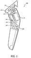
- the grooming device 100 may comprise a motor 130 for driving the cutting element 110.
- the motor 130 is supported in a motor housing 140, which is attached to a sub frame 150 of the grooming device 100.
- a spindle 160 comprising a helical gear is configured to move longitudinally with respect to a spindle wheel 170 upon being rotated. Longitudinal movement of the spindle 160 is configured to vary the distance between the cutting element 110 and the comb attachment 120.
- the apparatus comprises a first rotation member 200, which can be rotated to set the distance between the cutting element 110 and the comb attachment 120 by cooperation with the spindle 160.
- the first rotation member 200 may therefore be referred to as an adjustment wheel of the grooming device 100.
- the first rotation member 200 is rotatable through a predetermined rotation angle between first and second stop positions, which may respectively correspond to a maximum and a minimum distance between the hair cutting element 110 and the comb attachment 120.
- the first rotation member 200 cooperates with a second rotation member 300 and a third member 400 when rotating between the first and second stop positions.
- the first rotation member 200 may be axially aligned with the second rotation member 300 such that the first 200 and second 300 rotation members are rotatable about the same axis.
- the first 200 and second 300 rotation members may also be axially aligned with the third member 400, which is fixed with respect to the rotation axis of the first and second members 200, 300.
- the first rotation member 200 is configured to cooperate with the second and third members 300, 400 such that the first and second stop positions of the first rotation member 200 can be spaced by a rotation angle exceeding 360 degrees.
- the first rotation member 200 can be used for fine adjustment of the distance between the cutting element 110 and the comb attachment 120 of the grooming device 100.
- FIG. 3 illustrates the first rotation stage.
- Figures 4A and 4B illustrate the second rotation stage. The overview will be followed by a detailed description of the individual members 200, 300, 400.
- first rotation stage illustrated in Figure 3
- the first rotation member 200 can rotate with respect to the second rotation member 300 and the third member 400 through a first predetermined rotation angle.
- the first rotation member 200 Upon rotating through the first predetermined rotation angle, the first rotation member 200 is configured to engage with the second rotation member 300.
- engagement of the first and second rotation members 200, 300 may be caused by a projection 210 of the first rotation member 200 abutting a first projection 310 of the second rotation member 300.
- the first and second rotation members 200, 300 can rotate together through a second predetermined rotation angle.
- the second rotation member 300 is configured to engage with the third member 400.
- engagement of the second and third members 300, 400 may be caused by a second projection 320 on a rear face of the second rotation member 300 abutting a projection 410 of the third member 400.
- the third member 400 is not rotatable, and therefore further rotation of the first and second rotation members 200, 300 in the same direction is prevented.
- the position at which the second rotation member 300 engages with the third member 400 corresponds to the second stop position of the first rotation member 200.
- the first rotation member 200 can rotate in an opposite direction back to the first stop position in a manner which reflects the rotation described above. Specifically, the first rotation member 200 can rotate back through the first predetermined rotation angle before engaging again with the second rotation member 300 and driving a rotation of the second rotation member 300 back through the second predetermined rotation angle. Upon being rotated back through the second predetermined rotation angle the second rotation member 300 engages again with the third member 400, the fixed nature of which prevents further rotation of the first and second rotation members 200, 300. Reengagement between the second rotation member 300 and the third member 400 may be caused by the second projection 320 of the second rotation member 300 abutting an opposite side of the projection 410 of the third member 400. This is clearly illustrated in Figure 4B . The position at which the second rotation member 300 re-engages with the third member 400 corresponds to the first stop position of the first rotation member 200.
- the rotation angle of the first rotation member 200 between the first and second stop positions is therefore the sum of the first and second predetermined rotation angles referred to above. In the example shown in Figures 3 and 4 , this angle is approximately 600 degrees. Therefore, if the first rotation member 200 is configured such that its rotation directly actuates the position of a comb attachment 120 with respect to a hair cutting element 110, the first rotation member 200 can be used to accurately set the cutting length of the grooming device 100. This is described in the example below.
- the first rotation member 200 may comprise a driving means such as a drive gear 220.
- the drive gear 220 is coupled to a driving mechanism, for example comprising the spindle 160 and spindle wheel 170, such that the drive gear 220 and driving mechanism are configured to actuate the comb attachment 120 when the first rotation member 200 is rotated.
- the drive gear 220 and driving mechanism may be configured such that rotation of the first rotation member 200 in a first direction causes an increase in the distance between the comb attachment 120 and the cutting element 110 by moving the comb attachment 120 away from the cutting element 110.
- the drive gear 220 and driving mechanism may be configured such that rotation of the first rotation member 200 in a second, opposite direction causes a decrease in the distance between the comb attachment 120 and the cutting element 110 by moving the comb attachment 120 closer to the cutting element 110.
- the drive gear 220 and the associated driving mechanism could be configured to move the cutting element 110 rather than the comb attachment 120 to achieve the same variation in cutting length to that described above.
- the first rotation member 200 may comprise an outer part 230, an intermediate part 240 and the drive gear 220. All three parts 220, 230, 240 are fixed relative to each other such that they rotate together about the same axis of rotation.
- the outer part 230 may have a substantially cylindrical shape, with a grip element 231 provided at its outwardly facing circumferential surface.
- the grip element 231 is configured to allow a user to easily rotate the first rotation member 200 between the first and second stop positions.
- the grip element 231 may comprise a layer of high friction material such as rubber.
- the intermediate part 240 may also have a substantially cylindrical shape. It may be located substantially concentrically inwardly from the outer part 230 such that an outwardly facing circumferential surface of the intermediate part 240 is in contact with an inwardly facing circumferential surface of the outer part 230. This allows the inwardly facing circumferential surface of the outer part 230 to be fixed to the outwardly facing circumferential surface of the intermediate part 240, for example using suitable adhesive. As shown in Figure 2A , projections on the inwardly facing surface of the outer part 230 may extend into correspondingly shaped depressions in the outwardly facing surface of the intermediate part 240 to provide a more secure fixing. It will be appreciated that projections on the outwardly facing circumferential surface of the intermediate part 240 may additionally or alternatively extend into corresponding depressions on the inwardly facing circumferential surface of the outer part 230.
- the drive gear 220 may have substantially cylindrical or ring-like shape. As shown in Figures 2 to 4 , it has a ring of driving teeth configured to cooperate with the driving mechanism to actuate the comb attachment 120.
- the drive gear 220 may be located substantially concentrically inwardly from the intermediate and outer parts 240, 230 such that an outwardly facing surface of the drive gear 220 can be fixed to an inwardly facing surface of the intermediate part 240.
- the fixing can be achieved using a suitable adhesive. As described above in relation to the fixing between the outer and intermediate parts 230, 240, projections extending into correspondingly shaped depressions may be employed to provide a more secure fixing.
- outer part 230, intermediate part 240 and drive gear 220 of the first rotation member 200 are described herein as three separate elements, they may alternatively be two elements or a single element.
- the outer part 230, intermediate part 240 and drive gear 220 may therefore simply correspond to outer, intermediate and inner regions of the first rotation member 200.
- the second rotation member 300 may be substantially cylindrical in form. This is clearly shown in Figure 2B . However, as shown in the Figures, it is not essential that the second rotation member 300 has a significant depth compared to its circumference, and so it may alternatively be described as being ring shaped. The rotational centre of the second rotation member 300 may be located axially with the rotational centre of the first rotation member 200.
- the third member 400 may comprise a substantially cylindrical section of the main body of the grooming device 100. It may, for example, be coupled to the sub frame 150 of the grooming device 100. The centre of an end radial surface of the third member 400 may be located axially with the rotational centre of the first and second rotation members 200, 300.
- the first rotation member 200 comprises a projection 210.
- the projection 210 extends in an axial direction from a radial surface of the first rotation member 200 towards a first radial surface of the second rotation member 300, which faces the radial surface of the first rotation member 200 and is substantially parallel to it.
- the first radial surface of the second rotation member 300 is shown in Figure 5A .
- the projection 210 is shown as extending from the drive gear 220 part of the first rotation member 200. However, the projection 210 may alternatively extend from either of the outer part 230 or intermediate part 240 of the first rotation member 200.
- the projection 210 of the first rotation member 200 is accommodated in an arcuate recess 330 of the first radial surface of the second rotation member 300 and can move along the recess 330 to allow relative rotation of the first rotation member 200 and the second rotation member 300 in the first rotation stage referred to above.
- movement of the projection 210 with respect to the second rotation member 300 is restricted by a first projection 310 of the second rotation member 300.
- the first projection 310 of the second rotation member 300 extends in an axial direction from the first radial surface of the second rotation member 300 towards the radial surface of the first rotation member 200.
- the first projection 310 of the second rotation member 300 is accommodated in an arcuate recess 250 of the radial surface of the first rotation member 200 along which it can move during the first rotation stage to allow relative rotation of the first and second rotation members 200, 300.
- the projection 210 of the first rotation member 200 reaches the end of the arcuate recess 330 in the first radial surface of the second rotation member 300 and abuts the first projection 310 of the second rotation member 300 to drive a rotation of the second rotation member 300 through a second predetermined rotation angle.
- a second (opposite) radial surface of the second rotation member 300 is shown in Figure 5B . It is also shown in cooperation with the third member 400 in Figure 4B .
- the second radial surface of the second rotation member 300 is substantially parallel to first radial surface of the second rotation member 300 and the radial surface of the first rotation member 200.
- the second radial surface of the second rotation member 300 comprises a second projection 320, which extends in an axial direction away from the second radial surface of the second rotation member 300 towards a radial surface of the third member 400.
- the radial surface of the third member 400 is substantially parallel to the radial surface of the first rotation member 200 and the first and second radial surfaces of the second rotation member 300.
- the second projection 320 of the second rotation member 300 is accommodated in an arcuate recess 420 in the radial surface of the third member 400 and can move along the recess 420 to allow the second rotation member 300 to rotate with respect to the third member 400 in the second rotation stage referred to above.
- the third member 400 is not rotatable, and may be fixed relative to a main body of the grooming device 100 as previously described. Movement of the second projection 320 with respect to the third member 400 is restricted by a projection 410 of the third member 400. As shown in Figure 4B , the projection 410 of the third member 400 extends in an axial direction from the radial surface of the third member 400 towards the second radial surface of the second rotation member 300.
- the projection 410 of the third member 400 is accommodated in an arcuate recess 340 in the second radial surface of the second rotation member 300 along which it can move during the second rotation stage to allow the second rotation member 300 to rotate with respect to the third member 400.
- the second projection 320 of the second rotation member 300 reaches the end of the arcuate recess 420 in the third member 400 and abuts the projection 410 of the third member 400.
- the abutment of the second projection 320 of the second rotation member 300 with the projection 410 of the third member 400 prevents further rotation of both the first and second rotation members 200, 300.
- the projection 410 of the third member 400 therefore comprises an end stop, which provides the first and second stop positions of the first rotation member 200.
- An alternative solution to providing an adjustment wheel rotatable through an angle exceeding 360 degrees between first and second stop positions is to provide end stops on the spindle wheel 170 to restrict longitudinal movement of the spindle 160 rather than rotation of the wheel.
- the invention provides an advantage over this solution in that the end stop 410 is more robust, and less prone to damage when the adjustment wheel 100 is over-rotated.
- the apparatus is described herein in terms of adjusting the distance between a comb attachment and a cutting element in a grooming device, the apparatus could alternatively be used for adjusting the distance between first and second elements of any kind, and is therefore not limited to use in grooming devices.
- the adjustment apparatus according to the current invention may be implemented in an element preventing an excess amount of rotation. Such an implementation could be beneficial in the limitation of the rotation of a screw or bolt preventing damage to soft materials or damage from overturning a bolt or screw.
- Another example of an alternative use of the adjusting apparatus according to the invention is the limitation of the travelling distance of a rolling device such a guiding wheel of a drawer running in a guiding groove limiting the rotation of the guiding wheel to a certain amount of degrees, thus to a corresponding travelling distance.
- a rolling device such as a guiding wheel of a drawer running in a guiding groove
- Such an implementation could be beneficial in preventing the drawer to run out of its guiding groove during opening, causing a potentially dangerous situation to the user as well as an unpleasant mess to be cleaned by the user.
- the person skilled in the art will appreciate the wide applicability of the current invention in both domestic and industrial apparatuses.
- first and second rotation members 200, 300 it will be appreciated that further rotation members could be incorporated between the second rotation member and the third member to increase the rotation angle between the first and second stop positions of the first rotation member.
- a third rotation member having first and second radial surfaces corresponding to the first and second radial surfaces of the second rotation member 300 could be employed between the second rotation member 300 and the third member to increase the maximum rotation angle of the first rotation member.
Landscapes
- Life Sciences & Earth Sciences (AREA)
- Forests & Forestry (AREA)
- Engineering & Computer Science (AREA)
- Mechanical Engineering (AREA)
- Dry Shavers And Clippers (AREA)
- Preliminary Treatment Of Fibers (AREA)
- Aiming, Guidance, Guns With A Light Source, Armor, Camouflage, And Targets (AREA)
- Transmission Devices (AREA)
- Measurement Of Optical Distance (AREA)
Claims (12)
- Justagevorrichtung zum Justieren eines Abstandes zwischen ersten und zweiten Elementen, folgendes umfassend
ein erstes Drehelement (200), das zwischen ersten und zweiten Stopp-Positionen verdreht werden kann, wobei die Drehung des ersten Drehelements zwischen der ersten und zweiten Stopp-Position 360 Grad übersteigt, wobei das erste Drehelement (200) ein Antriebsmittel (220) umfasst, das mit einem Antriebsmechanismus verbunden ist, und
ein zweites Drehelement (300),
wobei der besagte Antriebsmechanismus und die Antriebsmittel (220) ausgeführt sind, um eine Bewegung in die Position des ersten Elements im Verhältnis zur Position des zweiten Elements anzutreiben, wenn das erste Drehelement zwischen der ersten Stopp-Position und der zweiten Stopp-Position verdreht wird, um einen Abstand zwischen dem ersten und zweiten Element zu justieren, und
dadurch gekennzeichnet, dass das erste und zweite Drehelement axial ausgerichtet sind, und wobei die Drehung des ersten Drehelements zwischen der ersten und zweiten Stopp-Position eine erste Drehstufe umfasst, in der sich das erste Drehelement um einen ersten Drehwinkel dreht, und eine zweite Drehstufe, in der das erste Drehelement konfiguriert ist, um ins zweite Drehelement einzugreifen, um das zweite Drehelement um einen zweiten Drehwinkel zu verdrehen. - Justagevorrichtung nach Anspruch 1, wobei das erste Drehelement einen sich axial erstreckenden Ansatz (210) umfasst, der konfiguriert ist, um sich an einen sich axial erstreckenden Ansatz (310) des zweiten Drehelements anzulegen, um das erste Drehelement ins zweite Drehelement eingreifen zu lassen.
- Justagevorrichtung nach Anspruch 2, wobei der sich axial erstreckende Ansatz des ersten Drehelements konfiguriert ist, um sich durch eine bogenförmige Ausnehmung (330) des zweiten Drehelements zu erstrecken, entlang der sich der axial estreckende Ansatz des ersten Drehelements laut Konfiguration während der ersten Drehstufe bewegt.
- Justagevorrichtung nach irgendeinem der vorherigen Ansprüche, darüber hinaus ein drittes Element (400) umfassend, das konfiguriert ist, um bei der Drehung des zweiten Drehelements um den zweiten Drehwinkel ins zweite Drehelement einzugreifen, um eine weitere Drehung des ersten und zweiten Drehelements zu verhindern.
- Justagevorrichtung nach Anspruch 4, wobei das dritte Element einen Endanschlag umfasst, der einen sich axial erstreckenden Ansatz (410) umfasst, der konfiguriert ist, um sich an einen zweiten sich axial erstreckenden Ansatz (320) des zweiten Drehelements anzulegen, um das dritte Element ins zweite Drehelement eingreifen zu lassen, um eine weitere Drehung des ersten und zweiten Drehelements zu verhindern.
- Justagevorrichtung nach Anspruch 5, wobei der zweite sich axial erstreckende Ansatz des zweiten Drehelements konfiguriert ist, um sich durch eine bogenförmige Ausnehmung (420) des dritten Elements zu erstrecken, entlang der er sich laut Konfiguration während der ersten Drehstufe bewegt.
- Justagevorrichtung nach irgendeinem der vorherigen Ansprüche, wobei das erste Drehelement einen äußeren Griff zum Verdrehen des ersten Drehelements in der ersten und zweiten Drehstufe umfasst.
- Justagevorrichtung nach Anspruch 1, wobei das erste Element entweder einen Aufsatzkamm oder ein Haarschneideelement umfasst, und das zweite Element das andere Element des Aufsatzkamms und Haarschneideelements umfasst.
- Pflegegerät, eine Vorrichtung nach irgendeinem der vorherigen Ansprüche umfassend.
- Pflegegerät nach Anspruch 9, wobei die erste Stopp-Position einer Einstellung für eine Mindesthaarschnittlänge entspricht und die zweite Stopp-Position einer Einstellung für eine Maximalhaarschnittlänge entspricht.
- Verfahren zur Justage eines Abstandes zwischen ersten und zweiten Elementen, wie einem Haarschneideelement und einem Aufsatzkamm auf einem Pflegegerät, folgendes umfassend:Drehen eines ersten Drehelements von einer ersten Stopp-Position um einen ersten Drehwinkel;Eingreifen des ersten Drehelements in ein zweites Drehelement;Weiterdrehen des ersten Drehelements um einen zweiten Drehwinkel in die zweite Stopp-Position, wobei die Drehung des ersten Drehelements zwischen der ersten Stopp-Position und der zweiten Stopp-Position eine Bewegung des ersten Elements in die Position im Verhältnis zur Position des zweiten Elements antreibt, um einen Abstand zwischen dem ersten und dem zweiten Element zu justieren, und wobei der Eingriff zwischen dem ersten Drehelement und dem zweiten Drehelement das zweite Drehelement dazu bringt, sich um den zweiten Drehwinkel zu drehen, und wobei die Drehung des ersten Drehelements zwischen der ersten und der zweiten Stopp-Position 360 Grad übersteigt.
- Verfahren nach Anspruch 11, wobei das zweite Drehelement beim Verdrehen um den zweiten Drehwinkel in ein drittes Drehelement eingreift, und das Eingreifen zwischen dem zweiten Drehelement und dem dritten Element eine weitere Drehung des ersten und zweiten Drehelements verhindert.
Priority Applications (1)
| Application Number | Priority Date | Filing Date | Title |
|---|---|---|---|
| EP10807379.2A EP2512759B1 (de) | 2009-12-14 | 2010-12-07 | Vorrichtung mit Drehelement |
Applications Claiming Priority (3)
| Application Number | Priority Date | Filing Date | Title |
|---|---|---|---|
| EP09179008A EP2332701A1 (de) | 2009-12-14 | 2009-12-14 | Vorrichtung mit Drehelement |
| PCT/IB2010/055621 WO2011073850A1 (en) | 2009-12-14 | 2010-12-07 | Apparatus comprising rotatable member |
| EP10807379.2A EP2512759B1 (de) | 2009-12-14 | 2010-12-07 | Vorrichtung mit Drehelement |
Publications (2)
| Publication Number | Publication Date |
|---|---|
| EP2512759A1 EP2512759A1 (de) | 2012-10-24 |
| EP2512759B1 true EP2512759B1 (de) | 2016-04-27 |
Family
ID=42169454
Family Applications (2)
| Application Number | Title | Priority Date | Filing Date |
|---|---|---|---|
| EP09179008A Withdrawn EP2332701A1 (de) | 2009-12-14 | 2009-12-14 | Vorrichtung mit Drehelement |
| EP10807379.2A Active EP2512759B1 (de) | 2009-12-14 | 2010-12-07 | Vorrichtung mit Drehelement |
Family Applications Before (1)
| Application Number | Title | Priority Date | Filing Date |
|---|---|---|---|
| EP09179008A Withdrawn EP2332701A1 (de) | 2009-12-14 | 2009-12-14 | Vorrichtung mit Drehelement |
Country Status (10)
| Country | Link |
|---|---|
| US (1) | US9308656B2 (de) |
| EP (2) | EP2332701A1 (de) |
| JP (1) | JP5731533B2 (de) |
| KR (1) | KR101845054B1 (de) |
| CN (1) | CN102655992B (de) |
| BR (1) | BR112012014034B1 (de) |
| CA (1) | CA2784101C (de) |
| ES (1) | ES2579308T3 (de) |
| RU (1) | RU2553791C2 (de) |
| WO (1) | WO2011073850A1 (de) |
Families Citing this family (11)
| Publication number | Priority date | Publication date | Assignee | Title |
|---|---|---|---|---|
| US8341846B1 (en) | 2008-11-24 | 2013-01-01 | Lonnie Holmes | Hair clippers with electrically adjustable blades |
| US8844142B2 (en) | 2011-03-18 | 2014-09-30 | Spectrum Brands, Inc. | Adjustable comb assembly for hair cutting appliance |
| FR2985211B1 (fr) | 2011-12-28 | 2014-08-29 | Seb Sa | Tondeuse avec molette retractable |
| RU2689002C2 (ru) | 2014-05-09 | 2019-05-23 | Конинклейке Филипс Н.В. | Регулируемый разделительный гребень, регулировочный привод и устройство для стрижки волос |
| CN104308871B (zh) * | 2014-08-25 | 2015-12-02 | 温州市日电电器有限公司 | 一种具有可调支架的修剪器 |
| EP3575049A1 (de) * | 2018-05-30 | 2019-12-04 | Koninklijke Philips N.V. | Haarführungs- und haarschneideanordnung |
| CN115056268B (zh) * | 2022-05-06 | 2024-08-20 | 利民(番禺南沙)电器发展有限公司 | 一种理发器 |
| USD1045226S1 (en) | 2022-07-27 | 2024-10-01 | E. Mishan & Sons, Inc. | Vacuum shaver |
| US12290947B2 (en) * | 2022-08-19 | 2025-05-06 | Raymond Industrial Ltd. | Beard trimmer |
| USD981043S1 (en) | 2022-12-12 | 2023-03-14 | E. Mishan & Sons, Inc. | Shaver |
| US20250339984A1 (en) * | 2024-05-03 | 2025-11-06 | WORX4U2, Inc. | Modular clippers |
Family Cites Families (24)
| Publication number | Priority date | Publication date | Assignee | Title |
|---|---|---|---|---|
| DE1090544B (de) | 1959-07-10 | 1960-10-06 | Feinmechanik Vormals Jetter & | Haarschneidemaschine |
| US3263328A (en) * | 1965-04-22 | 1966-08-02 | Burnie J Craig | Adjustable disposable razor |
| US3709055A (en) * | 1971-01-04 | 1973-01-09 | L Grove | Gear tooth profile |
| SU1293023A1 (ru) * | 1985-05-29 | 1987-02-28 | Харьковское Производственное Объединение "Электробытприбор" | Запорное устройство откидной режущей головки электробритвы |
| US4845852A (en) | 1987-10-23 | 1989-07-11 | Andis Company | Hair trimmer with adjustable comb |
| NL8800132A (nl) * | 1988-01-21 | 1989-08-16 | Philips Nv | Haarknipapparaat. |
| US5367772A (en) | 1992-05-26 | 1994-11-29 | Matsushita Electric Works, Ltd. | Hair clipper |
| JP3092780B2 (ja) * | 1994-11-22 | 2000-09-25 | 文博 藤田 | ヘアカッター装置 |
| JPH08279324A (ja) * | 1995-04-05 | 1996-10-22 | Toshiba Corp | 抵抗付きガス遮断器 |
| US5970616A (en) * | 1997-12-22 | 1999-10-26 | Wahl Clipper Corporation | Hair trimmer with lighted rotating head |
| KR100314192B1 (ko) | 1999-11-17 | 2001-11-15 | 오태준 | 전기바리캉 |
| JP2003074381A (ja) * | 2001-08-31 | 2003-03-12 | Toyota Motor Corp | スロットル弁及びスロットル弁機構 |
| AU2003224372A1 (en) * | 2002-05-21 | 2003-12-02 | Koninklijke Philips Electronics N.V. | Apparatus for treating a person's skin |
| ES2380663T3 (es) | 2002-09-06 | 2012-05-17 | Koninklijke Philips Electronics N.V. | Aparato de higiene personal con un cabezal que puede pivotar automáticamente |
| JP4046051B2 (ja) * | 2003-08-29 | 2008-02-13 | 松下電工株式会社 | ヘアカッターの刈り高さ調整機構 |
| JP4046052B2 (ja) * | 2003-08-29 | 2008-02-13 | 松下電工株式会社 | ヘアカッターのコーム振動防止構造 |
| IL160955A0 (en) * | 2004-03-18 | 2004-08-31 | Epilady 2000 Llc | Comb adjusting mechanism for hair clipper |
| DE102004031378A1 (de) * | 2004-06-28 | 2006-01-12 | Lutter & Partner Gmbh | Haar- und/oder Bartschneidegerät |
| WO2007004204A1 (en) | 2005-07-04 | 2007-01-11 | Epilady 2000 Llc | Rotary extendable hair clipper |
| DE102005044175A1 (de) * | 2005-09-16 | 2007-03-29 | Braun Gmbh | Haarentfernungsgerät |
| US7234242B2 (en) | 2005-11-14 | 2007-06-26 | Woody Yao | Adjustable apparatus for hair clipper |
| ITMI20070304A1 (it) * | 2007-02-16 | 2008-08-17 | Perfect Steam Appliances Ltd | Macchinetta ad azionamento manuale per tagliare i capelli. |
| JP2010131267A (ja) * | 2008-12-05 | 2010-06-17 | Panasonic Electric Works Co Ltd | ヘアカッター用のアタッチメント |
| FR2985211B1 (fr) * | 2011-12-28 | 2014-08-29 | Seb Sa | Tondeuse avec molette retractable |
-
2009
- 2009-12-14 EP EP09179008A patent/EP2332701A1/de not_active Withdrawn
-
2010
- 2010-12-07 KR KR1020127018118A patent/KR101845054B1/ko not_active Expired - Fee Related
- 2010-12-07 CN CN201080056702.1A patent/CN102655992B/zh active Active
- 2010-12-07 WO PCT/IB2010/055621 patent/WO2011073850A1/en not_active Ceased
- 2010-12-07 EP EP10807379.2A patent/EP2512759B1/de active Active
- 2010-12-07 BR BR112012014034-5A patent/BR112012014034B1/pt not_active IP Right Cessation
- 2010-12-07 CA CA2784101A patent/CA2784101C/en active Active
- 2010-12-07 US US13/509,697 patent/US9308656B2/en active Active
- 2010-12-07 JP JP2012542665A patent/JP5731533B2/ja not_active Expired - Fee Related
- 2010-12-07 RU RU2012129885/02A patent/RU2553791C2/ru active
- 2010-12-07 ES ES10807379.2T patent/ES2579308T3/es active Active
Also Published As
| Publication number | Publication date |
|---|---|
| EP2512759A1 (de) | 2012-10-24 |
| JP5731533B2 (ja) | 2015-06-10 |
| CA2784101C (en) | 2018-03-06 |
| JP2013513416A (ja) | 2013-04-22 |
| RU2012129885A (ru) | 2014-01-27 |
| KR101845054B1 (ko) | 2018-04-04 |
| CN102655992A (zh) | 2012-09-05 |
| BR112012014034B1 (pt) | 2020-09-29 |
| EP2332701A1 (de) | 2011-06-15 |
| RU2553791C2 (ru) | 2015-06-20 |
| CN102655992B (zh) | 2015-07-08 |
| US9308656B2 (en) | 2016-04-12 |
| WO2011073850A1 (en) | 2011-06-23 |
| BR112012014034A2 (pt) | 2017-10-24 |
| ES2579308T3 (es) | 2016-08-09 |
| US20130239416A1 (en) | 2013-09-19 |
| KR20120101123A (ko) | 2012-09-12 |
| CA2784101A1 (en) | 2011-06-23 |
Similar Documents
| Publication | Publication Date | Title |
|---|---|---|
| EP2512759B1 (de) | Vorrichtung mit Drehelement | |
| JP4837835B2 (ja) | チャック | |
| EP3162499B1 (de) | Verstellbarer hubmechanismus für exzentermaschinen | |
| ES2821946T3 (es) | Dispositivo de freno para un motor de accionamiento eléctrico | |
| ES2938862T3 (es) | Herramienta de instalación para un inserto de rosca de alambre | |
| JP7008871B2 (ja) | 毛切断機器 | |
| KR101587404B1 (ko) | 하나 이상의 멈춤부를 포함하는 자동차 시트용 조절 장치 | |
| WO2015174474A1 (ja) | 開閉体開閉装置 | |
| KR102703966B1 (ko) | 양 베어링 릴 | |
| JP2022506358A (ja) | 改良されたキャップ機能性を備えるシェービング装置 | |
| US6785971B2 (en) | Electric powered rotary hacksaw | |
| KR20210064277A (ko) | 면도 장치를 위한 개선된 모발-절삭 유닛 | |
| WO2019102558A1 (ja) | 作業機 | |
| KR101384516B1 (ko) | 자력을 이용한 슬립토크 조절기능을 갖는 토크 리미트 드라이버 | |
| CN107264409B (zh) | 视觉辨认装置的视觉辨认角度调整机构 | |
| EP3991895A1 (de) | Verblendmaschine zum verhindern des einströmens von schneidspänen in ein rohr | |
| JP2020101252A (ja) | コイルばねを利用したロックタイプ双方向クラッチ | |
| US10870196B2 (en) | Tool having an auto-adjusting handle | |
| KR102152336B1 (ko) | 스핀들 록킹장치와 이를 적용한 전동공구 및 차량용 액츄에이터 | |
| JP3638810B2 (ja) | ねじ締め機のサイレントクラッチ | |
| JP4607555B2 (ja) | ヘッジトリマ | |
| JP6358221B2 (ja) | ギア装置 | |
| CN1823573A (zh) | 具有卷轴保护器的修整设备 | |
| JP6755368B1 (ja) | リンク機構を利用した逆入力遮断装置 | |
| CN110072681A (zh) | 皮带切割机 |
Legal Events
| Date | Code | Title | Description |
|---|---|---|---|
| PUAI | Public reference made under article 153(3) epc to a published international application that has entered the european phase |
Free format text: ORIGINAL CODE: 0009012 |
|
| 17P | Request for examination filed |
Effective date: 20120716 |
|
| AK | Designated contracting states |
Kind code of ref document: A1 Designated state(s): AL AT BE BG CH CY CZ DE DK EE ES FI FR GB GR HR HU IE IS IT LI LT LU LV MC MK MT NL NO PL PT RO RS SE SI SK SM TR |
|
| DAX | Request for extension of the european patent (deleted) | ||
| RAP1 | Party data changed (applicant data changed or rights of an application transferred) |
Owner name: KONINKLIJKE PHILIPS N.V. |
|
| 17Q | First examination report despatched |
Effective date: 20130927 |
|
| GRAP | Despatch of communication of intention to grant a patent |
Free format text: ORIGINAL CODE: EPIDOSNIGR1 |
|
| INTG | Intention to grant announced |
Effective date: 20151111 |
|
| GRAS | Grant fee paid |
Free format text: ORIGINAL CODE: EPIDOSNIGR3 |
|
| GRAA | (expected) grant |
Free format text: ORIGINAL CODE: 0009210 |
|
| AK | Designated contracting states |
Kind code of ref document: B1 Designated state(s): AL AT BE BG CH CY CZ DE DK EE ES FI FR GB GR HR HU IE IS IT LI LT LU LV MC MK MT NL NO PL PT RO RS SE SI SK SM TR |
|
| REG | Reference to a national code |
Ref country code: GB Ref legal event code: FG4D |
|
| REG | Reference to a national code |
Ref country code: CH Ref legal event code: EP |
|
| REG | Reference to a national code |
Ref country code: AT Ref legal event code: REF Ref document number: 794202 Country of ref document: AT Kind code of ref document: T Effective date: 20160515 |
|
| REG | Reference to a national code |
Ref country code: IE Ref legal event code: FG4D |
|
| REG | Reference to a national code |
Ref country code: DE Ref legal event code: R096 Ref document number: 602010032903 Country of ref document: DE |
|
| REG | Reference to a national code |
Ref country code: ES Ref legal event code: FG2A Ref document number: 2579308 Country of ref document: ES Kind code of ref document: T3 Effective date: 20160809 |
|
| REG | Reference to a national code |
Ref country code: LT Ref legal event code: MG4D |
|
| REG | Reference to a national code |
Ref country code: NL Ref legal event code: MP Effective date: 20160427 |
|
| REG | Reference to a national code |
Ref country code: AT Ref legal event code: MK05 Ref document number: 794202 Country of ref document: AT Kind code of ref document: T Effective date: 20160427 |
|
| PG25 | Lapsed in a contracting state [announced via postgrant information from national office to epo] |
Ref country code: NL Free format text: LAPSE BECAUSE OF FAILURE TO SUBMIT A TRANSLATION OF THE DESCRIPTION OR TO PAY THE FEE WITHIN THE PRESCRIBED TIME-LIMIT Effective date: 20160427 |
|
| PG25 | Lapsed in a contracting state [announced via postgrant information from national office to epo] |
Ref country code: PL Free format text: LAPSE BECAUSE OF FAILURE TO SUBMIT A TRANSLATION OF THE DESCRIPTION OR TO PAY THE FEE WITHIN THE PRESCRIBED TIME-LIMIT Effective date: 20160427 Ref country code: NO Free format text: LAPSE BECAUSE OF FAILURE TO SUBMIT A TRANSLATION OF THE DESCRIPTION OR TO PAY THE FEE WITHIN THE PRESCRIBED TIME-LIMIT Effective date: 20160727 Ref country code: LT Free format text: LAPSE BECAUSE OF FAILURE TO SUBMIT A TRANSLATION OF THE DESCRIPTION OR TO PAY THE FEE WITHIN THE PRESCRIBED TIME-LIMIT Effective date: 20160427 Ref country code: FI Free format text: LAPSE BECAUSE OF FAILURE TO SUBMIT A TRANSLATION OF THE DESCRIPTION OR TO PAY THE FEE WITHIN THE PRESCRIBED TIME-LIMIT Effective date: 20160427 |
|
| PG25 | Lapsed in a contracting state [announced via postgrant information from national office to epo] |
Ref country code: LV Free format text: LAPSE BECAUSE OF FAILURE TO SUBMIT A TRANSLATION OF THE DESCRIPTION OR TO PAY THE FEE WITHIN THE PRESCRIBED TIME-LIMIT Effective date: 20160427 Ref country code: GR Free format text: LAPSE BECAUSE OF FAILURE TO SUBMIT A TRANSLATION OF THE DESCRIPTION OR TO PAY THE FEE WITHIN THE PRESCRIBED TIME-LIMIT Effective date: 20160728 Ref country code: HR Free format text: LAPSE BECAUSE OF FAILURE TO SUBMIT A TRANSLATION OF THE DESCRIPTION OR TO PAY THE FEE WITHIN THE PRESCRIBED TIME-LIMIT Effective date: 20160427 Ref country code: AT Free format text: LAPSE BECAUSE OF FAILURE TO SUBMIT A TRANSLATION OF THE DESCRIPTION OR TO PAY THE FEE WITHIN THE PRESCRIBED TIME-LIMIT Effective date: 20160427 Ref country code: PT Free format text: LAPSE BECAUSE OF FAILURE TO SUBMIT A TRANSLATION OF THE DESCRIPTION OR TO PAY THE FEE WITHIN THE PRESCRIBED TIME-LIMIT Effective date: 20160829 Ref country code: SE Free format text: LAPSE BECAUSE OF FAILURE TO SUBMIT A TRANSLATION OF THE DESCRIPTION OR TO PAY THE FEE WITHIN THE PRESCRIBED TIME-LIMIT Effective date: 20160427 Ref country code: RS Free format text: LAPSE BECAUSE OF FAILURE TO SUBMIT A TRANSLATION OF THE DESCRIPTION OR TO PAY THE FEE WITHIN THE PRESCRIBED TIME-LIMIT Effective date: 20160427 |
|
| REG | Reference to a national code |
Ref country code: FR Ref legal event code: PLFP Year of fee payment: 7 |
|
| PG25 | Lapsed in a contracting state [announced via postgrant information from national office to epo] |
Ref country code: BE Free format text: LAPSE BECAUSE OF FAILURE TO SUBMIT A TRANSLATION OF THE DESCRIPTION OR TO PAY THE FEE WITHIN THE PRESCRIBED TIME-LIMIT Effective date: 20160427 |
|
| REG | Reference to a national code |
Ref country code: DE Ref legal event code: R097 Ref document number: 602010032903 Country of ref document: DE |
|
| PG25 | Lapsed in a contracting state [announced via postgrant information from national office to epo] |
Ref country code: SK Free format text: LAPSE BECAUSE OF FAILURE TO SUBMIT A TRANSLATION OF THE DESCRIPTION OR TO PAY THE FEE WITHIN THE PRESCRIBED TIME-LIMIT Effective date: 20160427 Ref country code: DK Free format text: LAPSE BECAUSE OF FAILURE TO SUBMIT A TRANSLATION OF THE DESCRIPTION OR TO PAY THE FEE WITHIN THE PRESCRIBED TIME-LIMIT Effective date: 20160427 Ref country code: CZ Free format text: LAPSE BECAUSE OF FAILURE TO SUBMIT A TRANSLATION OF THE DESCRIPTION OR TO PAY THE FEE WITHIN THE PRESCRIBED TIME-LIMIT Effective date: 20160427 Ref country code: EE Free format text: LAPSE BECAUSE OF FAILURE TO SUBMIT A TRANSLATION OF THE DESCRIPTION OR TO PAY THE FEE WITHIN THE PRESCRIBED TIME-LIMIT Effective date: 20160427 Ref country code: RO Free format text: LAPSE BECAUSE OF FAILURE TO SUBMIT A TRANSLATION OF THE DESCRIPTION OR TO PAY THE FEE WITHIN THE PRESCRIBED TIME-LIMIT Effective date: 20160427 |
|
| PG25 | Lapsed in a contracting state [announced via postgrant information from national office to epo] |
Ref country code: SM Free format text: LAPSE BECAUSE OF FAILURE TO SUBMIT A TRANSLATION OF THE DESCRIPTION OR TO PAY THE FEE WITHIN THE PRESCRIBED TIME-LIMIT Effective date: 20160427 |
|
| PLBE | No opposition filed within time limit |
Free format text: ORIGINAL CODE: 0009261 |
|
| STAA | Information on the status of an ep patent application or granted ep patent |
Free format text: STATUS: NO OPPOSITION FILED WITHIN TIME LIMIT |
|
| 26N | No opposition filed |
Effective date: 20170130 |
|
| PG25 | Lapsed in a contracting state [announced via postgrant information from national office to epo] |
Ref country code: SI Free format text: LAPSE BECAUSE OF FAILURE TO SUBMIT A TRANSLATION OF THE DESCRIPTION OR TO PAY THE FEE WITHIN THE PRESCRIBED TIME-LIMIT Effective date: 20160427 |
|
| REG | Reference to a national code |
Ref country code: CH Ref legal event code: PL |
|
| PG25 | Lapsed in a contracting state [announced via postgrant information from national office to epo] |
Ref country code: MC Free format text: LAPSE BECAUSE OF FAILURE TO SUBMIT A TRANSLATION OF THE DESCRIPTION OR TO PAY THE FEE WITHIN THE PRESCRIBED TIME-LIMIT Effective date: 20160427 |
|
| REG | Reference to a national code |
Ref country code: IE Ref legal event code: MM4A |
|
| PG25 | Lapsed in a contracting state [announced via postgrant information from national office to epo] |
Ref country code: LI Free format text: LAPSE BECAUSE OF NON-PAYMENT OF DUE FEES Effective date: 20161231 Ref country code: LU Free format text: LAPSE BECAUSE OF NON-PAYMENT OF DUE FEES Effective date: 20161207 Ref country code: CH Free format text: LAPSE BECAUSE OF NON-PAYMENT OF DUE FEES Effective date: 20161231 |
|
| PG25 | Lapsed in a contracting state [announced via postgrant information from national office to epo] |
Ref country code: IE Free format text: LAPSE BECAUSE OF NON-PAYMENT OF DUE FEES Effective date: 20161207 |
|
| REG | Reference to a national code |
Ref country code: FR Ref legal event code: PLFP Year of fee payment: 8 |
|
| PG25 | Lapsed in a contracting state [announced via postgrant information from national office to epo] |
Ref country code: HU Free format text: LAPSE BECAUSE OF FAILURE TO SUBMIT A TRANSLATION OF THE DESCRIPTION OR TO PAY THE FEE WITHIN THE PRESCRIBED TIME-LIMIT; INVALID AB INITIO Effective date: 20101207 Ref country code: CY Free format text: LAPSE BECAUSE OF FAILURE TO SUBMIT A TRANSLATION OF THE DESCRIPTION OR TO PAY THE FEE WITHIN THE PRESCRIBED TIME-LIMIT Effective date: 20160427 |
|
| PG25 | Lapsed in a contracting state [announced via postgrant information from national office to epo] |
Ref country code: IS Free format text: LAPSE BECAUSE OF FAILURE TO SUBMIT A TRANSLATION OF THE DESCRIPTION OR TO PAY THE FEE WITHIN THE PRESCRIBED TIME-LIMIT Effective date: 20160427 Ref country code: TR Free format text: LAPSE BECAUSE OF FAILURE TO SUBMIT A TRANSLATION OF THE DESCRIPTION OR TO PAY THE FEE WITHIN THE PRESCRIBED TIME-LIMIT Effective date: 20160427 Ref country code: MK Free format text: LAPSE BECAUSE OF FAILURE TO SUBMIT A TRANSLATION OF THE DESCRIPTION OR TO PAY THE FEE WITHIN THE PRESCRIBED TIME-LIMIT Effective date: 20160427 |
|
| PG25 | Lapsed in a contracting state [announced via postgrant information from national office to epo] |
Ref country code: BG Free format text: LAPSE BECAUSE OF FAILURE TO SUBMIT A TRANSLATION OF THE DESCRIPTION OR TO PAY THE FEE WITHIN THE PRESCRIBED TIME-LIMIT Effective date: 20160427 |
|
| PG25 | Lapsed in a contracting state [announced via postgrant information from national office to epo] |
Ref country code: MT Free format text: LAPSE BECAUSE OF NON-PAYMENT OF DUE FEES Effective date: 20161207 |
|
| PG25 | Lapsed in a contracting state [announced via postgrant information from national office to epo] |
Ref country code: AL Free format text: LAPSE BECAUSE OF FAILURE TO SUBMIT A TRANSLATION OF THE DESCRIPTION OR TO PAY THE FEE WITHIN THE PRESCRIBED TIME-LIMIT Effective date: 20160427 |
|
| PGFP | Annual fee paid to national office [announced via postgrant information from national office to epo] |
Ref country code: IT Payment date: 20211220 Year of fee payment: 12 |
|
| PGFP | Annual fee paid to national office [announced via postgrant information from national office to epo] |
Ref country code: ES Payment date: 20220110 Year of fee payment: 12 |
|
| REG | Reference to a national code |
Ref country code: ES Ref legal event code: FD2A Effective date: 20240126 |
|
| PG25 | Lapsed in a contracting state [announced via postgrant information from national office to epo] |
Ref country code: IT Free format text: LAPSE BECAUSE OF NON-PAYMENT OF DUE FEES Effective date: 20221207 |
|
| PG25 | Lapsed in a contracting state [announced via postgrant information from national office to epo] |
Ref country code: ES Free format text: LAPSE BECAUSE OF NON-PAYMENT OF DUE FEES Effective date: 20221208 |
|
| PG25 | Lapsed in a contracting state [announced via postgrant information from national office to epo] |
Ref country code: ES Free format text: LAPSE BECAUSE OF NON-PAYMENT OF DUE FEES Effective date: 20221208 |
|
| PGFP | Annual fee paid to national office [announced via postgrant information from national office to epo] |
Ref country code: GB Payment date: 20251223 Year of fee payment: 16 |
|
| PGFP | Annual fee paid to national office [announced via postgrant information from national office to epo] |
Ref country code: FR Payment date: 20251222 Year of fee payment: 16 |
|
| PGFP | Annual fee paid to national office [announced via postgrant information from national office to epo] |
Ref country code: DE Payment date: 20251229 Year of fee payment: 16 |