EP2512866B1 - Dispositif pour fixer un objet dans une cavité - Google Patents
Dispositif pour fixer un objet dans une cavité Download PDFInfo
- Publication number
- EP2512866B1 EP2512866B1 EP10787063.6A EP10787063A EP2512866B1 EP 2512866 B1 EP2512866 B1 EP 2512866B1 EP 10787063 A EP10787063 A EP 10787063A EP 2512866 B1 EP2512866 B1 EP 2512866B1
- Authority
- EP
- European Patent Office
- Prior art keywords
- blocking
- anchoring element
- cover part
- cover
- base part
- Prior art date
- Legal status (The legal status is an assumption and is not a legal conclusion. Google has not performed a legal analysis and makes no representation as to the accuracy of the status listed.)
- Active
Links
Images




Classifications
-
- F—MECHANICAL ENGINEERING; LIGHTING; HEATING; WEAPONS; BLASTING
- F16—ENGINEERING ELEMENTS AND UNITS; GENERAL MEASURES FOR PRODUCING AND MAINTAINING EFFECTIVE FUNCTIONING OF MACHINES OR INSTALLATIONS; THERMAL INSULATION IN GENERAL
- F16B—DEVICES FOR FASTENING OR SECURING CONSTRUCTIONAL ELEMENTS OR MACHINE PARTS TOGETHER, e.g. NAILS, BOLTS, CIRCLIPS, CLAMPS, CLIPS OR WEDGES; JOINTS OR JOINTING
- F16B5/00—Joining sheets or plates, e.g. panels, to one another or to strips or bars parallel to them
- F16B5/12—Fastening strips or bars to sheets or plates, e.g. rubber strips, decorative strips for motor vehicles, by means of clips
-
- B—PERFORMING OPERATIONS; TRANSPORTING
- B60—VEHICLES IN GENERAL
- B60R—VEHICLES, VEHICLE FITTINGS, OR VEHICLE PARTS, NOT OTHERWISE PROVIDED FOR
- B60R13/00—Elements for body-finishing, identifying, or decorating; Arrangements or adaptations for advertising purposes
- B60R13/04—External Ornamental or guard strips; Ornamental inscriptive devices thereon
-
- B—PERFORMING OPERATIONS; TRANSPORTING
- B60—VEHICLES IN GENERAL
- B60R—VEHICLES, VEHICLE FITTINGS, OR VEHICLE PARTS, NOT OTHERWISE PROVIDED FOR
- B60R9/00—Supplementary fittings on vehicle exterior for carrying loads, e.g. luggage, sports gear or the like
- B60R9/04—Carriers associated with vehicle roof
- B60R9/058—Carriers associated with vehicle roof characterised by releasable attaching means between carrier and roof
-
- F—MECHANICAL ENGINEERING; LIGHTING; HEATING; WEAPONS; BLASTING
- F16—ENGINEERING ELEMENTS AND UNITS; GENERAL MEASURES FOR PRODUCING AND MAINTAINING EFFECTIVE FUNCTIONING OF MACHINES OR INSTALLATIONS; THERMAL INSULATION IN GENERAL
- F16B—DEVICES FOR FASTENING OR SECURING CONSTRUCTIONAL ELEMENTS OR MACHINE PARTS TOGETHER, e.g. NAILS, BOLTS, CIRCLIPS, CLAMPS, CLIPS OR WEDGES; JOINTS OR JOINTING
- F16B21/00—Means for preventing relative axial movement of a pin, spigot, shaft or the like and a member surrounding it; Stud-and-socket releasable fastenings
- F16B21/06—Releasable fastening devices with snap-action
- F16B21/065—Releasable fastening devices with snap-action with an additional locking element
-
- F—MECHANICAL ENGINEERING; LIGHTING; HEATING; WEAPONS; BLASTING
- F16—ENGINEERING ELEMENTS AND UNITS; GENERAL MEASURES FOR PRODUCING AND MAINTAINING EFFECTIVE FUNCTIONING OF MACHINES OR INSTALLATIONS; THERMAL INSULATION IN GENERAL
- F16B—DEVICES FOR FASTENING OR SECURING CONSTRUCTIONAL ELEMENTS OR MACHINE PARTS TOGETHER, e.g. NAILS, BOLTS, CIRCLIPS, CLAMPS, CLIPS OR WEDGES; JOINTS OR JOINTING
- F16B5/00—Joining sheets or plates, e.g. panels, to one another or to strips or bars parallel to them
- F16B5/06—Joining sheets or plates, e.g. panels, to one another or to strips or bars parallel to them by means of clamps or clips
- F16B5/0607—Joining sheets or plates, e.g. panels, to one another or to strips or bars parallel to them by means of clamps or clips joining sheets or plates to each other
- F16B5/0621—Joining sheets or plates, e.g. panels, to one another or to strips or bars parallel to them by means of clamps or clips joining sheets or plates to each other in parallel relationship
- F16B5/0628—Joining sheets or plates, e.g. panels, to one another or to strips or bars parallel to them by means of clamps or clips joining sheets or plates to each other in parallel relationship allowing for adjustment parallel or perpendicular to the plane of the sheets or plates
Definitions
- the invention relates to a device for fixing an object in a recess according to the preamble of claim 1.
- Such a device is off JP 2000 027 824 A or even out DE 10 2006 039 577 B3 known.
- the previously known device has a cover part, which is set up for engagement with a roof strip as an object.
- a releasably connectable to the cover part foot is present, which is designed for anchoring in a trained as a roof channel of a motor vehicle recess.
- the foot has in this prior art device via a laterally projecting abutment projection, which is contoured for engagement with a bent retaining edge of the roof channel.
- the device can be reliably fixed with sufficient dimensional stability of the retaining edge.
- the invention has for its object to provide a device of the type mentioned, which is characterized by a tolerances balancing, but nevertheless against relatively high mechanical loads resistant footboard. This object is achieved in a device of the type mentioned according to the invention with the characterizing features of claim 1.
- the foot part has an anchoring element which compensates for tolerances via the flexible connecting webs but which is fixed in a final assembly position via at least one blocking part, tolerances of a fastening element to be engaged with the anchoring element can be compensated for during assembly, but the stability of the foot part can be compensated is significantly increased by blocking the mobility of the anchoring element against an otherwise existing mobility.
- Fig. 1 shows in a perspective view an embodiment of a device according to the invention for fixing a in Fig. 1 roof strip, not shown as an object in an in Fig. 1 also not shown roof channel of a motor vehicle as a recess.
- the embodiment according to Fig. 1 has a cover part 1 and a foot part 2, which are designed in this embodiment as a separate, made of a hard elastic plastic material components.
- the cover part 1 has a large-area cover plate 3 of a substantially rectangular shape with long longitudinal sides and short transverse sides, in whose corner regions on the longitudinal sides outwardly projecting fixing tongues 4, 5, 6, 7 are formed.
- On a cover side of the cover plate 3 are adjacent to a transverse side of the cover plate 3 on the cover plate 3 projecting clamping ribs 8, 9, 10 are formed.
- two connecting webs 11, 12 are formed, which carry a parallel to this transverse side extending end plate 13.
- a spring arm 18 is formed, which extends away from the cover plate 3 and in a relaxed arrangement in the plane of arranged on this longitudinal side short side walls 15, 16.
- a locking lug 19 is formed, which projects beyond the spring arm 18 to the outside.
- the substantially cuboid-shaped foot part 2 of the exemplary device according to the invention Fig. 1 has on two short transverse sides side walls 20, 21 as walls, which are aligned at a distance parallel to each other.
- carrier webs 22, 23, 24, 25 are formed, which extend away from the side walls 20, 21 and edge strips 26, 27 carry. Between adjacent edge strips 26, 27 formed in a middle web 28 which extends in the direction of a cover side of the foot part 2.
- the edge sides of the carrier webs 22, 23, 24, 25 facing away from the side walls 20, 21 are provided with edge ribs 29 arranged in a stepped manner.
- each longitudinal wall 30, 31, 32, 33 carries a latching tongue 34, 35, 36, 37, which are arranged on the outer sides of the longitudinal walls 30, 31, 32, 33 and extend obliquely aligned from the top side of the foot part 2.
- a transverse web 38, 39, 40, 41 is formed in an end region facing away from the relevant side wall 20, 21, on which the respective longitudinal wall 30, 31, 32, 33 is formed extends outwards.
- the transverse webs 38, 39 which are arranged on the edge strips 26, 27 facing away from the side of the foot part 2, carry a guide plate 42 which is arranged at a distance from the respective longitudinal walls 30, 31.
- the other transverse webs 40, 41 merge into the central carrier webs 23, 24 and have support blocks 43, 44 aligned at right angles to the side walls 20, 21 and the longitudinal walls 30, 31, 32, 33.
- the cover part 2 has an anchoring element 45 lying approximately centrally between the side walls 20, 21 and the longitudinal walls 30, 31, 32, 33, which has a number of connecting webs 46, 47, 48, 49 with the side walls 20, 21 are connected.
- each one side wall 20, 21 and the anchoring element 45 each have two connecting webs 46, 47; 48, 49 available.
- the connecting webs 46, 47, 48, 49 are executed in this embodiment, wave-like or accordion-like and thus hold in the in Fig. 1 illustrated Vormontagean ever the anchoring element 45 with a certain mobility relative to a frame of the foot part 2 forming side walls 20, 21 and longitudinal walls 30, 31, 32, 33rd
- the exemplary device according to the invention is according to Fig. 1 equipped with a Randblock Arthuril 50 and a Stirnblock Arthuril 51 as blocking parts, which are connected to the foot part 2 via thin Anspitzstege immediately after manufacture.
- the Randblock Arthuril 50 is substantially U-shaped with a transverse portion 52 and two integrally formed at the respective opposite ends of the transverse portion 52 leg portions 53, 54 and formed in the arrangement according to Fig. 1 offset at right angles between the guide plate 42 and the anchoring element 45 is positioned.
- the Stirnblock investigatingil 52 encloses the guide plate 52 facing the edge region of the anchoring element 45, wherein the anchoring element 45 and the Randblock Arthur 50 via an array of parallel to the side walls 20, 21 and the longitudinal walls 30, 31, 32, 33 extending guide grooves 55 and guide ribs 56 against each other slidably engageable.
- a stop tongue 57 extending between the leg sections 53, 54 in the direction of the anchoring element 45 as well as claw noses 58 extending outwardly on the side of the leg sections 53, 54 remote from the transverse section 52 are formed on the edge blocking part 50.
- the Stirnblock investigatingil 51 is substantially L-shaped and arranged on the Randblock Ofil 50 opposite side of the anchoring element 45.
- the other leg portion 62 of Stirnblockêtiles 51 lies in the arrangement according to Fig. 1 between the inside transverse webs 40, 41 the support blocks 43, 44 at a distance opposite.
- claw noses 63 which face outward are formed on the end blocking part 51 on the leg sections 61, 62.
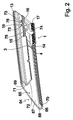
- Fig. 2 shows in a perspective view of the cover part 1 of the device according to the invention in the embodiment according to Fig. 1 engaged with a roof rail 64 of an in Fig. 2 not shown motor vehicle as an object.
- the roof strip 64 is constructed of a bent metal strip 65 and a cover layer 66 of a flexible material surrounding the metal strip 65 on an outer side.
- the metal band 65 is bent such that it has a substantially flat cover side 67, edge strips 68, 69 formed on the outside of the cover side 67, a parallel end section 70 extending from an edge bend 68 substantially parallel to the cover side 61, one from the other edge bend 69 Having approximately parallel to the top side 67 extending intermediate portion 71 and adjoining the intermediate portion 71 and extending approximately at right angles to the top side 67 transverse end portion 72 has.
- the cover part 1 is shown with its partially invisible fixing tongues 4, 5, 6, 7 in engagement with the edge arches 68, 69 of the roof rail 64, wherein the end plate 13 rests against a front end of the roof rail 64 and the locking tab 19 in a in the Transverse end portion 72 of the roof rail 64 engages recessed recess 73 engages.
- the cover part 1 is releasably fixed to the roof rail 64.
- the cover part 1 has an integrally formed on the long side cheek 14 transverse web 74 which extends from the long side cheek 14 in the direction of long side cheek 14 opposite short side cheeks 15, 16 extends.
- transverse web 74 which extends from the long side cheek 14 in the direction of long side cheek 14 opposite short side cheeks 15, 16 extends.
- two L-shaped angle webs 75, 76 are integrally formed, extending from the crosspiece 74 while enclosing the spring arm 18 in the direction of the long side cheek 14 opposite short side cheeks 15, 16 ,
- Fig. 3 shows in a perspective view of the foot part 2 in the embodiment according to the invention according to Fig. 1 and a roof channel 77 of a motor vehicle as a recess in which the foot part 2 is to be attached.
- a fixedly connected to the body of the motor vehicle stud bolt 78 is provided, which is composed of a extending from the bottom 79 of the roof channel 77 away bolt shaft 80 and a bolt head 81 which on the bottom 79 side facing away from the Stud shaft 80 is arranged and projects beyond the bolt shaft 80 radially.
- the anchoring element 45 is formed in the region of a bolt receptacle 82 open to the edge blocking part 50 with two lateral approach ramps 83 and a support step 84 extending between the approach ramps 83 on the edge blocking part 50.
- the approach ramps 83 in this case have a sloping in the direction of the guide plate 42 relative to the support step 84 slope, while the support step 84 is formed with a flat support surface for the bottom 79 facing bottom of the bolt head 81.
- the assembly process of the foot part 2 in the roof channel 77 begins by the fact that the foot part 2 obliquely with the bolt holder 82 is arranged in the region of the stud bolt 78 and moved so that the bolt head 81 enters the bolt receptacle 82, slides along the approach ramps 83 and finally rests on the support step 84.
- Fig. 4 shows in a perspective view anchored in the roof channel 77 arrangement of the foot part 2, in which the stud 78 is now arranged in the bolt receptacle 82 and both the Randblockêtil 50 and the Stirnblock Ofil 51 in a relation to the raised arrangement according to Fig. 1 and Fig. 3 lowered blocking arrangement are.
- this lowered arrangement grab as out Fig. 4 it can be seen that the claw lugs 58, 63 formed on the Randblockêtil 50 and the Stirnblockêtil 51 in the opposite transverse webs 38, 39 and edge strips 26, 27 as walls of the receiving spaces 85, 86, so that the anchoring element 45 in its original existing Mobility is blocked in the aligned along the transverse side tolerance compensation direction relative to the foot part 2.
- a mechanical stabilization of the anchoring element 45 takes place.
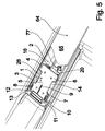
- Fig. 5 shows in a partially sectioned perspective view of the exemplary device according to the invention according to Fig. 1 with the roof panel 64 connected to the cover part 1 in engagement with the foot part 2, which is mounted in the roof channel 77.
- the fixing tongues 4, 5, 6, 7 formed on the foot part 2 engage in the latching lugs 17 formed on the cover part 1, compensating for height tolerances in the relative position of the roof rail 64 with respect to the floor 79 of the roof duct 77.
- How out Fig. 5 can be seen, can be in accordance with an embodiment of the cover part 1 Fig.
- Fig. 6 shows a sectional view of the arrangement of the cover part 1, the foot part 2 and the roof rail 64 in the roof duct 77. From the illustration according to Fig. 6 it can be seen that the fixing tongues 4, 5, 6, 7 are in engagement with the latching lugs 17, so that the cover part 1 is firmly fastened to the foot part 2. In the arrangement according to Fig. 6 can be due to the provision of several mutually parallel locking lugs 17, if necessary, the roof rail 64 at different altitudes, for example due to a release bias also later in a lower lowered arrangement with respect to the bottom 79 of the roof duct 77 bring.
Landscapes
- Engineering & Computer Science (AREA)
- General Engineering & Computer Science (AREA)
- Mechanical Engineering (AREA)
- Fittings On The Vehicle Exterior For Carrying Loads, And Devices For Holding Or Mounting Articles (AREA)
Claims (10)
- Dispositif pour la fixation d'un objet (64) dans une cavité (77), se composant d'un élément de recouvrement (1) qui est agencé pour pouvoir être mis en prise d'accouplement avec l'objet et se composant d'un élément formant semelle (2) qui est agencé pour pouvoir être ancré dans la cavité (77), l'élément de recouvrement (1) et l'élément formant semelle (2) étant en l'occurrence destinés à assemblés l'un avec l'autre, caractérisé en ce que l'élément formant semelle (2) est muni d'un élément d'ancrage (45) qui est agencé pour être mis en prise d'engagement avec un organe de fixation (79) disposé dans la cavité (77), en ce que l'élément d'ancrage (45) est raccordé au moyen d'un certain nombre de pontets de liaison élastiques (46, 47, 48, 49) à des parois extérieures (20, 21) de l'élément formant semelle (2) et en ce qu'il est prévu au-moins un élément de blocage (50, 51), au moyen duquel ou desquels il est possible, dans une position de blocage, d'immobiliser l'élément d'ancrage (45) par rapport aux parois extérieures (20, 21) dans différentes positions par rapport aux parois extérieures (20, 21).
- Dispositif selon la revendication 1, caractérisé en ce que le ou chaque pontet de liaison (46, 47, 48, 49) qui va de puis un côté en s'écartant de l'élément d'ancrage (45) a une configuration structurale ondulée ou en accordéon.
- Dispositif selon la revendication 1 ou la revendication 2, caractérisé en ce qu'il est prévu deux éléments de blocage (50, 51) au niveau de côtés de l'élément d'ancrage (45) se faisant respectivement face.
- Dispositif selon l'une des revendications 1 à 3, caractérisé en ce que chaque élément de blocage (50, 51) et l'élément d'ancrage (45) sont munis de rainures de guidage (55, 60) et de nervures de guidage (56, 61) qui s'imbriquent respectivement en prise d'encastrement.
- Dispositif selon l'une des revendications 1 à 4, caractérisé en ce que le ou chaque élément de blocage (50, 51) est, dans la position de blocage, disposé dans un espace de réception (85, 86) qui, dans une direction de rattrapage de variations dimensionnelles, est plus grand que l'élément de blocage (50, 51) concerné.
- Dispositif selon la revendication 5, caractérisé en ce que le ou chaque élément de blocage (50, 51) comporte au-moins un ergot de cramponnement (58, 63) qui, dans la position de blocage, opère en combinaison avec une paroi (26, 27, 38, 39) de l'espace de réception (85, 86) pour assurer l'immobilisation en position de l'élément de blocage (50, 51).
- Dispositif selon l'une des revendications 1 à 6, caractérisé en ce que l'élément de recouvrement (1) et l'élément formant semelle (2) sont respectivement assemblés avec une possibilité de dissociation ultérieure.
- Dispositif selon la revendication 7, caractérisé en ce que l'élément de recouvrement (1) et l'élément formant semelle (2) sont munis d'ergots d'encastrement (17) et de languettes d'immobilisation en position (4, 5, 6, 7) qui s'imbriquent respectivement en prise d'encastrement les uns dans les autres.
- Dispositif selon l'une des revendications 1 à 8, caractérisé en ce que l'élément d'ancrage (45) est agencé pour recevoir la tête (81) d'un organe de fixation (78), dont le diamètre est supérieur à celui d'une tige (80).
- Dispositif selon la revendication 7 ou la revendication 8, caractérisé en ce que l'élément de recouvrement (1) est muni d'éléments de poussée en contact d'engagement (74, 75, 76) qui, lors de l'emmanchement de l'élément de recouvrement (1) sur l'élément formant semelle (2), permettent d'agir sur chaque élément de blocage (50, 51) pour assurer le passage en position de blocage.
Applications Claiming Priority (2)
| Application Number | Priority Date | Filing Date | Title |
|---|---|---|---|
| DE200910058813 DE102009058813A1 (de) | 2009-12-18 | 2009-12-18 | Vorrichtung zum Fixieren eines Gegenstandes in einer Vertiefung |
| PCT/EP2010/068057 WO2011072994A1 (fr) | 2009-12-18 | 2010-11-23 | Dispositif pour fixer un objet dans une cavité |
Publications (2)
| Publication Number | Publication Date |
|---|---|
| EP2512866A1 EP2512866A1 (fr) | 2012-10-24 |
| EP2512866B1 true EP2512866B1 (fr) | 2016-02-10 |
Family
ID=43756802
Family Applications (1)
| Application Number | Title | Priority Date | Filing Date |
|---|---|---|---|
| EP10787063.6A Active EP2512866B1 (fr) | 2009-12-18 | 2010-11-23 | Dispositif pour fixer un objet dans une cavité |
Country Status (3)
| Country | Link |
|---|---|
| EP (1) | EP2512866B1 (fr) |
| DE (1) | DE102009058813A1 (fr) |
| WO (1) | WO2011072994A1 (fr) |
Families Citing this family (2)
| Publication number | Priority date | Publication date | Assignee | Title |
|---|---|---|---|---|
| TR201821233A2 (tr) * | 2018-12-31 | 2020-07-21 | Tofas Tuerk Otomobil Fabrikasi Anonim Sirketi | Bi̇r bağlanti yapisina sahi̇p tavan çitasi |
| FR3132059A1 (fr) * | 2022-01-26 | 2023-07-28 | Renault S.A.S | Véhicule doté d’un enjoliveur de pavillon ayant un montage simplifié |
Family Cites Families (8)
| Publication number | Priority date | Publication date | Assignee | Title |
|---|---|---|---|---|
| DE7618760U1 (fr) | Fa. A. Raymond, 7850 Loerrach | |||
| JP2997753B2 (ja) * | 1991-04-15 | 2000-01-11 | 日産自動車株式会社 | 装飾部品の取付構造 |
| DE9413049U1 (de) * | 1994-08-12 | 1995-02-23 | Julius & August Erbslöh GmbH & Co, 42553 Velbert | Vorrichtung zum Befestigen einer Abdeckleiste für Nuten von Kraftwagen-Aufbauten |
| JP2000027824A (ja) * | 1998-07-10 | 2000-01-25 | Togo Seisakusho Corp | ルーフモール用クリップ |
| DE102004056603A1 (de) | 2004-11-24 | 2006-06-01 | Rehau Ag + Co | Kunststoffanbauteil |
| DE602004025488D1 (de) * | 2004-12-24 | 2010-03-25 | Plastic Omnium Cie | Vorrichtung für die Montage einer Beleuchtungseinheit auf einem Kraftfahrzeug |
| DE102006039577B3 (de) | 2006-08-23 | 2008-01-03 | A. Raymond Et Cie | Vorrichtung zum Halten einer Leiste in einem Kanal |
| DE102007003319A1 (de) * | 2007-01-17 | 2008-07-24 | Newfrey Llc, Newark | Befestigungsclip und Bauteilverbindung mit einem Befestigungsclip |
-
2009
- 2009-12-18 DE DE200910058813 patent/DE102009058813A1/de not_active Withdrawn
-
2010
- 2010-11-23 WO PCT/EP2010/068057 patent/WO2011072994A1/fr not_active Ceased
- 2010-11-23 EP EP10787063.6A patent/EP2512866B1/fr active Active
Also Published As
| Publication number | Publication date |
|---|---|
| EP2512866A1 (fr) | 2012-10-24 |
| DE102009058813A1 (de) | 2011-06-22 |
| WO2011072994A1 (fr) | 2011-06-23 |
Similar Documents
| Publication | Publication Date | Title |
|---|---|---|
| WO2009039919A1 (fr) | Dispositif de fixation de deux composants sur un élément support | |
| DE102010035012A1 (de) | Vorrichtung zum Halten eines Anbauteiles an einem Trägerteil sowie Anordnung mit einer derartigen Vorrichtung und mit einem Anbauteil | |
| DE4309088A1 (de) | Ortsfest einbaubare Scheibe für Kraftfahrzeuge | |
| DE202018102231U1 (de) | Montageplattenanordnung mit mehrteiligem Montageplattenhalter | |
| DE102017108320A1 (de) | Flachteilhalter für die Befestigung eines Flachteils an einem Rahmengestell eines Schaltschranks und ein entsprechender Schaltschrank | |
| DE8802459U1 (de) | Gehäuse für ein elektrisches Gerät | |
| DE102017200349B4 (de) | Verbindungsteil zur verwendung für fahrzeugteile | |
| DE102007007514B4 (de) | Halteeinrichtung für eine Fahrzeugbatterie | |
| DE102017103595A1 (de) | Adapter und Verfahren zur Montage eines Schubkastens | |
| EP3026350B1 (fr) | Hotte aspirante dotée d'un composant | |
| WO2017144521A1 (fr) | Adaptateur de fixation d'un fond sur une joue latérale, tiroir avec un tel adaptateur et procédé de montage d'un fond sur un adaptateur | |
| DE102006039577B3 (de) | Vorrichtung zum Halten einer Leiste in einem Kanal | |
| WO2011072994A1 (fr) | Dispositif pour fixer un objet dans une cavité | |
| EP2657549B1 (fr) | Ecrou mâle | |
| EP2660403B1 (fr) | Support pour matière isolante | |
| EP2594165B1 (fr) | Support pour la fixation par serrage d'un objet, notamment d'un dispositif de tensionnement d'un cable pour un dispositif de pare-soleil et/ou de protection contre la vue, sur un cadre de fenêtre ou de porte | |
| WO2020058000A1 (fr) | Tiroir et unité constituée d'un guide de tiroir et d'un tiroir | |
| WO2010060633A1 (fr) | Clip de fixation en forme de u | |
| EP1587195A2 (fr) | Système de canalisation pour câble | |
| DE102015219814A1 (de) | Wagenheberaufnahme für einen Kraftwagen und Verfahren zur Montage einer solchen Wagenheberaufnahme | |
| DE69307314T2 (de) | Verbesserungen an randstreifen für bodenbeläge | |
| BE1028531B1 (de) | Befestigungseinrichtung, Verfahren, Anordnung und Schaltschrank | |
| DE69510627T2 (de) | Geräteträgereinrichtung Einzubringen auf einen Kabelkanalkörper | |
| DE102010005309A1 (de) | Verkleidungsteil mit mindestens einem Befestigungsmittel zur Befestigung an einer Fahrzeugkarosserie | |
| DE102009057177A1 (de) | Befestigungsanordnung für ein Profilteil an einem Trägerteil, insbesondere für eine seitliche Stoßfängerabdeckung an einem karosserieseitigen Trägerprofil |
Legal Events
| Date | Code | Title | Description |
|---|---|---|---|
| PUAI | Public reference made under article 153(3) epc to a published international application that has entered the european phase |
Free format text: ORIGINAL CODE: 0009012 |
|
| 17P | Request for examination filed |
Effective date: 20120718 |
|
| AK | Designated contracting states |
Kind code of ref document: A1 Designated state(s): AL AT BE BG CH CY CZ DE DK EE ES FI FR GB GR HR HU IE IS IT LI LT LU LV MC MK MT NL NO PL PT RO RS SE SI SK SM TR |
|
| DAX | Request for extension of the european patent (deleted) | ||
| RAP1 | Party data changed (applicant data changed or rights of an application transferred) |
Owner name: A. RAYMOND ET CIE |
|
| GRAP | Despatch of communication of intention to grant a patent |
Free format text: ORIGINAL CODE: EPIDOSNIGR1 |
|
| RIC1 | Information provided on ipc code assigned before grant |
Ipc: F16B 5/06 20060101ALI20150909BHEP Ipc: B60R 13/04 20060101AFI20150909BHEP Ipc: F16B 21/06 20060101ALI20150909BHEP Ipc: F16B 5/12 20060101ALI20150909BHEP Ipc: B60R 9/058 20060101ALI20150909BHEP |
|
| INTG | Intention to grant announced |
Effective date: 20151007 |
|
| GRAS | Grant fee paid |
Free format text: ORIGINAL CODE: EPIDOSNIGR3 |
|
| GRAA | (expected) grant |
Free format text: ORIGINAL CODE: 0009210 |
|
| AK | Designated contracting states |
Kind code of ref document: B1 Designated state(s): AL AT BE BG CH CY CZ DE DK EE ES FI FR GB GR HR HU IE IS IT LI LT LU LV MC MK MT NL NO PL PT RO RS SE SI SK SM TR |
|
| REG | Reference to a national code |
Ref country code: GB Ref legal event code: FG4D Free format text: NOT ENGLISH |
|
| REG | Reference to a national code |
Ref country code: AT Ref legal event code: REF Ref document number: 774485 Country of ref document: AT Kind code of ref document: T Effective date: 20160215 Ref country code: CH Ref legal event code: EP |
|
| REG | Reference to a national code |
Ref country code: IE Ref legal event code: FG4D Free format text: LANGUAGE OF EP DOCUMENT: GERMAN |
|
| REG | Reference to a national code |
Ref country code: DE Ref legal event code: R096 Ref document number: 502010011052 Country of ref document: DE |
|
| REG | Reference to a national code |
Ref country code: LT Ref legal event code: MG4D |
|
| REG | Reference to a national code |
Ref country code: NL Ref legal event code: MP Effective date: 20160210 |
|
| PG25 | Lapsed in a contracting state [announced via postgrant information from national office to epo] |
Ref country code: HR Free format text: LAPSE BECAUSE OF FAILURE TO SUBMIT A TRANSLATION OF THE DESCRIPTION OR TO PAY THE FEE WITHIN THE PRESCRIBED TIME-LIMIT Effective date: 20160210 Ref country code: FI Free format text: LAPSE BECAUSE OF FAILURE TO SUBMIT A TRANSLATION OF THE DESCRIPTION OR TO PAY THE FEE WITHIN THE PRESCRIBED TIME-LIMIT Effective date: 20160210 Ref country code: IT Free format text: LAPSE BECAUSE OF FAILURE TO SUBMIT A TRANSLATION OF THE DESCRIPTION OR TO PAY THE FEE WITHIN THE PRESCRIBED TIME-LIMIT Effective date: 20160210 Ref country code: NO Free format text: LAPSE BECAUSE OF FAILURE TO SUBMIT A TRANSLATION OF THE DESCRIPTION OR TO PAY THE FEE WITHIN THE PRESCRIBED TIME-LIMIT Effective date: 20160510 Ref country code: ES Free format text: LAPSE BECAUSE OF FAILURE TO SUBMIT A TRANSLATION OF THE DESCRIPTION OR TO PAY THE FEE WITHIN THE PRESCRIBED TIME-LIMIT Effective date: 20160210 Ref country code: GR Free format text: LAPSE BECAUSE OF FAILURE TO SUBMIT A TRANSLATION OF THE DESCRIPTION OR TO PAY THE FEE WITHIN THE PRESCRIBED TIME-LIMIT Effective date: 20160511 |
|
| PG25 | Lapsed in a contracting state [announced via postgrant information from national office to epo] |
Ref country code: PL Free format text: LAPSE BECAUSE OF FAILURE TO SUBMIT A TRANSLATION OF THE DESCRIPTION OR TO PAY THE FEE WITHIN THE PRESCRIBED TIME-LIMIT Effective date: 20160210 Ref country code: RS Free format text: LAPSE BECAUSE OF FAILURE TO SUBMIT A TRANSLATION OF THE DESCRIPTION OR TO PAY THE FEE WITHIN THE PRESCRIBED TIME-LIMIT Effective date: 20160210 Ref country code: LT Free format text: LAPSE BECAUSE OF FAILURE TO SUBMIT A TRANSLATION OF THE DESCRIPTION OR TO PAY THE FEE WITHIN THE PRESCRIBED TIME-LIMIT Effective date: 20160210 Ref country code: NL Free format text: LAPSE BECAUSE OF FAILURE TO SUBMIT A TRANSLATION OF THE DESCRIPTION OR TO PAY THE FEE WITHIN THE PRESCRIBED TIME-LIMIT Effective date: 20160210 Ref country code: PT Free format text: LAPSE BECAUSE OF FAILURE TO SUBMIT A TRANSLATION OF THE DESCRIPTION OR TO PAY THE FEE WITHIN THE PRESCRIBED TIME-LIMIT Effective date: 20160613 Ref country code: LV Free format text: LAPSE BECAUSE OF FAILURE TO SUBMIT A TRANSLATION OF THE DESCRIPTION OR TO PAY THE FEE WITHIN THE PRESCRIBED TIME-LIMIT Effective date: 20160210 Ref country code: SE Free format text: LAPSE BECAUSE OF FAILURE TO SUBMIT A TRANSLATION OF THE DESCRIPTION OR TO PAY THE FEE WITHIN THE PRESCRIBED TIME-LIMIT Effective date: 20160210 Ref country code: IS Free format text: LAPSE BECAUSE OF FAILURE TO SUBMIT A TRANSLATION OF THE DESCRIPTION OR TO PAY THE FEE WITHIN THE PRESCRIBED TIME-LIMIT Effective date: 20160610 |
|
| PG25 | Lapsed in a contracting state [announced via postgrant information from national office to epo] |
Ref country code: DK Free format text: LAPSE BECAUSE OF FAILURE TO SUBMIT A TRANSLATION OF THE DESCRIPTION OR TO PAY THE FEE WITHIN THE PRESCRIBED TIME-LIMIT Effective date: 20160210 Ref country code: EE Free format text: LAPSE BECAUSE OF FAILURE TO SUBMIT A TRANSLATION OF THE DESCRIPTION OR TO PAY THE FEE WITHIN THE PRESCRIBED TIME-LIMIT Effective date: 20160210 |
|
| REG | Reference to a national code |
Ref country code: DE Ref legal event code: R097 Ref document number: 502010011052 Country of ref document: DE |
|
| PG25 | Lapsed in a contracting state [announced via postgrant information from national office to epo] |
Ref country code: SK Free format text: LAPSE BECAUSE OF FAILURE TO SUBMIT A TRANSLATION OF THE DESCRIPTION OR TO PAY THE FEE WITHIN THE PRESCRIBED TIME-LIMIT Effective date: 20160210 Ref country code: RO Free format text: LAPSE BECAUSE OF FAILURE TO SUBMIT A TRANSLATION OF THE DESCRIPTION OR TO PAY THE FEE WITHIN THE PRESCRIBED TIME-LIMIT Effective date: 20160210 Ref country code: SM Free format text: LAPSE BECAUSE OF FAILURE TO SUBMIT A TRANSLATION OF THE DESCRIPTION OR TO PAY THE FEE WITHIN THE PRESCRIBED TIME-LIMIT Effective date: 20160210 Ref country code: CZ Free format text: LAPSE BECAUSE OF FAILURE TO SUBMIT A TRANSLATION OF THE DESCRIPTION OR TO PAY THE FEE WITHIN THE PRESCRIBED TIME-LIMIT Effective date: 20160210 |
|
| PLBE | No opposition filed within time limit |
Free format text: ORIGINAL CODE: 0009261 |
|
| STAA | Information on the status of an ep patent application or granted ep patent |
Free format text: STATUS: NO OPPOSITION FILED WITHIN TIME LIMIT |
|
| 26N | No opposition filed |
Effective date: 20161111 |
|
| PG25 | Lapsed in a contracting state [announced via postgrant information from national office to epo] |
Ref country code: SI Free format text: LAPSE BECAUSE OF FAILURE TO SUBMIT A TRANSLATION OF THE DESCRIPTION OR TO PAY THE FEE WITHIN THE PRESCRIBED TIME-LIMIT Effective date: 20160210 Ref country code: BG Free format text: LAPSE BECAUSE OF FAILURE TO SUBMIT A TRANSLATION OF THE DESCRIPTION OR TO PAY THE FEE WITHIN THE PRESCRIBED TIME-LIMIT Effective date: 20160510 Ref country code: BE Free format text: LAPSE BECAUSE OF NON-PAYMENT OF DUE FEES Effective date: 20161130 |
|
| REG | Reference to a national code |
Ref country code: CH Ref legal event code: PL |
|
| GBPC | Gb: european patent ceased through non-payment of renewal fee |
Effective date: 20161123 |
|
| PG25 | Lapsed in a contracting state [announced via postgrant information from national office to epo] |
Ref country code: LI Free format text: LAPSE BECAUSE OF NON-PAYMENT OF DUE FEES Effective date: 20161130 Ref country code: CH Free format text: LAPSE BECAUSE OF NON-PAYMENT OF DUE FEES Effective date: 20161130 |
|
| REG | Reference to a national code |
Ref country code: IE Ref legal event code: MM4A |
|
| REG | Reference to a national code |
Ref country code: FR Ref legal event code: ST Effective date: 20170731 |
|
| PG25 | Lapsed in a contracting state [announced via postgrant information from national office to epo] |
Ref country code: LU Free format text: LAPSE BECAUSE OF NON-PAYMENT OF DUE FEES Effective date: 20161130 |
|
| PG25 | Lapsed in a contracting state [announced via postgrant information from national office to epo] |
Ref country code: FR Free format text: LAPSE BECAUSE OF NON-PAYMENT OF DUE FEES Effective date: 20161130 |
|
| PG25 | Lapsed in a contracting state [announced via postgrant information from national office to epo] |
Ref country code: GB Free format text: LAPSE BECAUSE OF NON-PAYMENT OF DUE FEES Effective date: 20161123 Ref country code: IE Free format text: LAPSE BECAUSE OF NON-PAYMENT OF DUE FEES Effective date: 20161123 |
|
| REG | Reference to a national code |
Ref country code: AT Ref legal event code: MM01 Ref document number: 774485 Country of ref document: AT Kind code of ref document: T Effective date: 20161123 |
|
| PG25 | Lapsed in a contracting state [announced via postgrant information from national office to epo] |
Ref country code: AT Free format text: LAPSE BECAUSE OF NON-PAYMENT OF DUE FEES Effective date: 20161123 |
|
| REG | Reference to a national code |
Ref country code: BE Ref legal event code: MM Effective date: 20161130 |
|
| PG25 | Lapsed in a contracting state [announced via postgrant information from national office to epo] |
Ref country code: HU Free format text: LAPSE BECAUSE OF FAILURE TO SUBMIT A TRANSLATION OF THE DESCRIPTION OR TO PAY THE FEE WITHIN THE PRESCRIBED TIME-LIMIT; INVALID AB INITIO Effective date: 20101123 Ref country code: CY Free format text: LAPSE BECAUSE OF FAILURE TO SUBMIT A TRANSLATION OF THE DESCRIPTION OR TO PAY THE FEE WITHIN THE PRESCRIBED TIME-LIMIT Effective date: 20160210 |
|
| PG25 | Lapsed in a contracting state [announced via postgrant information from national office to epo] |
Ref country code: MK Free format text: LAPSE BECAUSE OF FAILURE TO SUBMIT A TRANSLATION OF THE DESCRIPTION OR TO PAY THE FEE WITHIN THE PRESCRIBED TIME-LIMIT Effective date: 20160210 Ref country code: MC Free format text: LAPSE BECAUSE OF FAILURE TO SUBMIT A TRANSLATION OF THE DESCRIPTION OR TO PAY THE FEE WITHIN THE PRESCRIBED TIME-LIMIT Effective date: 20160210 Ref country code: TR Free format text: LAPSE BECAUSE OF FAILURE TO SUBMIT A TRANSLATION OF THE DESCRIPTION OR TO PAY THE FEE WITHIN THE PRESCRIBED TIME-LIMIT Effective date: 20160210 |
|
| PG25 | Lapsed in a contracting state [announced via postgrant information from national office to epo] |
Ref country code: MT Free format text: LAPSE BECAUSE OF FAILURE TO SUBMIT A TRANSLATION OF THE DESCRIPTION OR TO PAY THE FEE WITHIN THE PRESCRIBED TIME-LIMIT Effective date: 20160210 |
|
| PG25 | Lapsed in a contracting state [announced via postgrant information from national office to epo] |
Ref country code: AL Free format text: LAPSE BECAUSE OF FAILURE TO SUBMIT A TRANSLATION OF THE DESCRIPTION OR TO PAY THE FEE WITHIN THE PRESCRIBED TIME-LIMIT Effective date: 20160210 |
|
| P01 | Opt-out of the competence of the unified patent court (upc) registered |
Effective date: 20230524 |
|
| REG | Reference to a national code |
Ref country code: DE Ref legal event code: R082 Ref document number: 502010011052 Country of ref document: DE Representative=s name: HOFFMANN EITLE PATENT- UND RECHTSANWAELTE PART, DE |
|
| PGFP | Annual fee paid to national office [announced via postgrant information from national office to epo] |
Ref country code: DE Payment date: 20251119 Year of fee payment: 16 |