EP2512921B1 - Druckstruktur mit kleinem durchmesser für den besatzungsruheraum eines passagierflugzeugs - Google Patents
Druckstruktur mit kleinem durchmesser für den besatzungsruheraum eines passagierflugzeugs Download PDFInfo
- Publication number
- EP2512921B1 EP2512921B1 EP10795530.4A EP10795530A EP2512921B1 EP 2512921 B1 EP2512921 B1 EP 2512921B1 EP 10795530 A EP10795530 A EP 10795530A EP 2512921 B1 EP2512921 B1 EP 2512921B1
- Authority
- EP
- European Patent Office
- Prior art keywords
- aircraft
- crew rest
- bunk
- aft
- area
- Prior art date
- Legal status (The legal status is an assumption and is not a legal conclusion. Google has not performed a legal analysis and makes no representation as to the accuracy of the status listed.)
- Active
Links
Images



Classifications
-
- B—PERFORMING OPERATIONS; TRANSPORTING
- B64—AIRCRAFT; AVIATION; COSMONAUTICS
- B64D—EQUIPMENT FOR FITTING IN OR TO AIRCRAFT; FLIGHT SUITS; PARACHUTES; ARRANGEMENT OR MOUNTING OF POWER PLANTS OR PROPULSION TRANSMISSIONS IN AIRCRAFT
- B64D11/00—Passenger or crew accommodation; Flight-deck installations not otherwise provided for
-
- B—PERFORMING OPERATIONS; TRANSPORTING
- B64—AIRCRAFT; AVIATION; COSMONAUTICS
- B64D—EQUIPMENT FOR FITTING IN OR TO AIRCRAFT; FLIGHT SUITS; PARACHUTES; ARRANGEMENT OR MOUNTING OF POWER PLANTS OR PROPULSION TRANSMISSIONS IN AIRCRAFT
- B64D11/00—Passenger or crew accommodation; Flight-deck installations not otherwise provided for
- B64D2011/0069—Rest berths, beds or the like
- B64D2011/0076—Rest berths, beds or the like for crew members, e.g. for sleeping during flight
-
- Y—GENERAL TAGGING OF NEW TECHNOLOGICAL DEVELOPMENTS; GENERAL TAGGING OF CROSS-SECTIONAL TECHNOLOGIES SPANNING OVER SEVERAL SECTIONS OF THE IPC; TECHNICAL SUBJECTS COVERED BY FORMER USPC CROSS-REFERENCE ART COLLECTIONS [XRACs] AND DIGESTS
- Y02—TECHNOLOGIES OR APPLICATIONS FOR MITIGATION OR ADAPTATION AGAINST CLIMATE CHANGE
- Y02T—CLIMATE CHANGE MITIGATION TECHNOLOGIES RELATED TO TRANSPORTATION
- Y02T50/00—Aeronautics or air transport
- Y02T50/40—Weight reduction
Definitions
- This invention relates generally to resting and sleeping quarters for an aircraft crew, and more particularly concerns overhead aircraft crew resting and sleeping quarters in a space-saving and weight-saving configuration occupying substantially otherwise unused space aboard an aircraft.
- Resting or sleeping facilities are commonly provided for the crew and passengers of ships, boats, trucks, buses, and the like when they are used for transportation of cargo or passengers over long distances.
- one conventional arrangement for a two- deck trailer includes upper deck and lower deck sections, with the upper deck section including beds and stairs leading from one end of the lower deck to a central area of the upper deck.
- Bunks for crew members aboard ship are typically constructed of heavy metal frames bolted together to provide a heavy structure inappropriate for aircraft.
- One known conventional aircraft crew rest facility includes configurations having 6 or 7 bunks. However, the crew rest facility is located in the lower lobe cargo bay of the aircraft, and occupies otherwise valuable cargo space, resulting in a loss of full freight capability for the aircraft. The weight of the crew rest facility is approximately 2,200 pounds, which further limits the capacity of the aircraft for carrying cargo or passengers.
- Another known design for an aircraft overhead crew rest station includes bunk portions forward and aft of a central deck portion with left and right side bunk portions, and a central entry vestibule connected between the central deck portion and a passenger seating area below, and providing direct access to the central deck portion and bunk portions of the aircraft crew rest station.
- Another conventional configuration for an aircraft overhead rest area includes an escape system in the crown of an aircraft above the ceiling in the main passenger cabin.
- a permanent access stairway is provided at one end of the overhead rest area, and an emergency escape includes a slide that can swing between a upward closed position and a downward open position.
- DE 2007 035681A1 (equivalent to US 2010 140402A ) discloses a residence and sleeping module for accommodating at least one member of an aircraft crew.
- the preamble of claim 1 is based on this document.
- the module may have a section for fitting in the space overlying a passenger seating area and has a central access stairway.
- EP 1364874A1 (equivalent to US 2003 218095A ) discloses aircraft passenger seating and bed modules which are shaped and fitted together to minimize overall space.
- EP 0901962A discloses an overhead crew rest area provided in the crown of an aircraft above the main passenger cabin ceiling, including an emergency escape apparatus.
- an emergency escape hatch that exits into cabin aisleway, and a fold-down jump seat or auxiliary seat for optional seating during taxi, take-off and landing in the common deck area, typically adjacent to the emergency escape hatch. It would also be desirable to provide a combination fold-down entry door and floor cover in the stairwell or ladder area of a central vestibule to expand common area floor space, to provide increased capacity for crew members, occupying an area of the aircraft that is otherwise generally unused. It is also desirable to provide a crew rest and sleeping station that has a space-saving and weight-saving configuration that minimizes the reduction in capacity of the aircraft for carrying cargo or passengers. Embodiments of the present invention meet these and other needs.
- the present invention provides for an improved aircraft crew rest station that optimize spatial accommodation of crew members in available aircraft space in an overhead crown area of the aircraft.
- the aircraft typically includes a hull with a curved top portion, a lowered ceiling, and a space therebetween, and the overhead crew rest station is configured to occupy the space between the curved top portion of the hull of the aircraft and the lowered ceiling of the aircraft, with an entry vestibule providing access to the overhead crew rest station.
- the present invention provides for a crew rest station for an aircraft as set out in claim 1.
- the forward bunk portion of the overhead crew rest portion includes three partitioned forward bunks, and the aft bunk portion of the overhead crew rest portion includes three partitioned aft bunks.
- each of the forward and aft bunk portions extends from the central deck portion in a direction approximately parallel to the hull center line of the aircraft.
- the crew rest station may include an emergency escape hatch, and a fold-down jump seat typically adjacent to the emergency escape hatch.
- the crew rest station includes a fold-down entry door that removably covers a stairwell or ladder area of the central vestibule, to expand the usable common area floor space of the crew rest station.
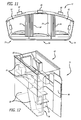
- FIG. 1 illustrates an improved aircraft crew rest station for an aircraft used for long distance flights. More particularly with reference to Figs. 1 and 6 , in a presently preferred embodiment, there is provided an improved crew rest station 20 for an aircraft 22, such as the Airbus A330/A340 for example, having a hull 24 with a curved top portion 26, a lowered ceiling 28, and a space 30 therebetween, typically provided for overhead stowage bins 32, and various types of ducting 34 above a passenger seating area 36.
- the aircraft crew rest station is typically located approximately in the aircraft midsection 38, adjacent door number three 40, and attached to the airframe of the aircraft.
- the crew rest station includes an overhead crew rest portion 42 with a forward bunk portion 44, an aft bunk portion 46, and a central deck portion 48.
- Each of the forward and aft bunk portions extends from the central deck portion, preferably in a direction approximately parallel to a hull center line 50 of the aircraft.
- the forward bunk portion includes a plurality of individual forward bunks or sleeping berths 52, separated by partitions 54, and each having individual entrances 56.
- the aft bunk portion similarly includes a plurality of individual aft bunks or sleeping berths 58, separated by partitions 60, and each having an individual entrance or entry 62.
- Each of the entrances to the individual bunks or sleeping berths preferably can be curtained with moveable curtains 64 to provide individual privacy and darkness for each individual bunk or sleeping berth.
- Each of the individual forward and aft bunks or sleeping berths also preferably includes individual overhead passenger service units (PSU) 66, which typically provide lighting, ventilation or air supply, call buttons, and the like.
- PSU passenger service unit
- a passenger service unit is also typically provided in the overhead area of the central deck portion.
- Accommodations for all bunk positions or sleeping berths typically include an emergency oxygen mask, a reading light, an air flow nozzle, also commonly known in the industry as a gasper, a main distribution vent air, personal stowage, the privacy curtain, and a mattress.
- the central deck portion provides a common entry and changing area, preferably located approximately midway between the forward and aft bunk portions, providing common access to the individual entrances to the partitioned individual forward and aft bunks or sleeping berths of the bunk portions.
- the maximum head height in the central deck common changing area is approximately 72 inches (about 183cms)
- each of the individual bunks or sleeping berths are typically approximately 80 inches (about 203cms) long, and provide a space of approximately 30 inches (about 76cms) high from the top of a mattress in the bunks or sleeping berth to the ceiling crown.
- the forward bunk portion, aft bunk portion and the central deck portion are typically configured to be located against the curved top portion of the hull of the aircraft to fit in the space between the hull and the lowered ceiling of the aircraft.
- the forward bunk portion of the overhead crew rest portion includes three partitioned forward bunks
- the aft bunk portion of the overhead crew rest portion includes three partitioned aft bunks, providing six bunk or sleeping berth arrangements for each aircraft crew rest station.
- the plurality of adjacent partitioned individual bunks or sleeping berths in the forward and aft bunk portions are configured in interfitting alternating trapezoid shapes, having a head end 68 that is wider than a foot end 70 of the individual bunks or sleeping berths, to optimize spatial accommodation of body proportions of crew members in the available aircraft space in the overhead crown area of the aircraft above the passenger cabin area, while still maintaining FAA bunk size and volume requirements.
- the head ends of the trapezoid shaped bunks or sleeping berths are typically approximately 30 inches (about 76cms) wide, and the foot ends of the trapezoid shaped bunks or sleeping berths are typically approximately 25 inches (about 63.5cms) wide, for example.
- access to the crew rest station from the passenger seating area is preferably provided by an entry stairs or ladder 72 extending up through an entry stairway or ladder area 74 provided in a generally centrally located entry vestibule 76, connected between the passenger seating area and the central deck portion of the crew rest station, and providing direct access to the central deck portion of said overhead crew rest portion.
- the crew rest station preferably includes sufficient space to provide all the amenities and emergency equipment that would be necessary to satisfy the flight regulations.
- the overhead crew rest portion is typically formed of a lightweight composite material, such as fiberglass, for example, and can be molded as a single unit for increased strength, so that the unit does not need to be bolted together.
- the overhead crew rest portion can be formed of modular sections, with the forward bunk portion being formed of a forward modular section, and the aft bunk portion being formed of an aft modular section, which can be connected together with a central deck module, all preferably formed of molded composite material, such as fiberglass.
- a crew rest station of a larger or smaller capacity could also be provided by simply increasing or reducing the number of bunks or sleeping berths, and that a flight crew rest station could be provided at other locations in the aircraft as well, such as a forward flight crew rest station with two bunks or sleeping berths, for example.
- the typical hoop frame of the aircraft supports and allows for sufficient space for the overhead crew rest portion in otherwise unused space of the aircraft. Modification of an existing aircraft configuration for installation of the aircraft crew rest station involves creation of a new ceiling contour, and the loss of a maximum of eight passenger area stowage bins. The overhead crew rest portion located between the hull and lowered ceiling of the aircraft thus does not impinge upon the passenger seating area or the cargo area of the aircraft.
- the center deck portion of the overhead crew rest portion also preferably includes an emergency escape hatch 80 that exits into cabin aisleway, a fold-down or folding jump seat 82 typically adjacent to the emergency escape hatch, and a stowage cabinet 84.
- the crew rest station also includes a fold-down entry door 86 that removably covers the entry stairway or ladder area of the central vestibule, to expand the usable common area floor space of the crew rest station.
- the vestibule also economically provides additional stowage space 88.
- Accommodations for the central entry vestibule and the common area and changing area of the central deck portion include personal stowage provisions for cabin crew, fold down seat, smoke detection, emergency lighting, emergency equipment, cabin interphone, temperature and lighting information indicators and control panel, seating and stowage, an emergency escape hatch, and stowage with cabin access.
Landscapes
- Engineering & Computer Science (AREA)
- Aviation & Aerospace Engineering (AREA)
- Emergency Lowering Means (AREA)
- Aiming, Guidance, Guns With A Light Source, Armor, Camouflage, And Targets (AREA)
Claims (7)
- Flugbesatzungsruheraum für ein Flugzeug (22) mit einem Rumpf (24) mit einem gewölbten oberen Abschnitt (26a), einer unteren Decke (28), die über einem Passagiersitzbereich (36) liegt, und einem Raum (30) dazwischen, der über einem Passagiersitzbereich (36) unter der unteren Decke (28) liegt;
wobei der Flugbesatzungsruheraum (20) Folgendes aufweist:einen Überkopf-Besatzungsruheabschnitt (42), der so geformt ist, dass er den Raum (30) zwischen dem gewölbten oberen Abschnitt (26a) des Rumpfes (24) des Flugzeugs (22) und der unteren Decke (28) des Flugzeugs einnimmt;wobei der Überkopf-Besatzungsruheabschnitt (42) einen zentralen Deckabschnitt (48), einen mit einem vorderen Abschnitt des zentralen Deckabschnitts (48) verbundenen vorderen Schlafkabinenabschnitt (44) und einen hinteren Schlafkabinenabschnitt (46) einschließt, der mit einem hinteren Abschnitt des zentralen Deckmoduls (48) verbunden ist;wobei der vordere Schlafkabinenabschnitt (44) eine Mehrzahl von benachbarten individuellen vorderen Schlafplätzen (52) einschließt, die durch Abtrennungen (54) voneinander abgetrennt sind und jeweils einen entsprechenden individuellen Eingang (56) aufweisen, und wobei der hintere Schlafkabinenabschnitt (46) eine Mehrzahl von benachbarten individuellen hinteren Schlafplätzen (53) einschließt, die durch Abtrennungen (60) voneinander abgetrennt sind und jeweils einen entsprechenden individuellen Eingang (62) aufweisen;und einen zentralen Eingangsvorraum (76) zum Verbinden des zentralen Deckabschnitts (48) mit dem Passagiersitzbereich (36) des Flugzeugs, um einen direkten Zugang zu dem zentralen Deckabschnitt (48) bereitzustellen; dadurch gekennzeichnet, dassdie Mehrzahl von benachbarten individuellen Schlafplätzen (52, 58) in dem vorderen und hinteren Schlafkabinenabschnitt (44, 46) als ineinanderpassende sich abwechselnde Trapezformen ausgestaltet sind, um die räumliche Unterbringung von Körperproportionen von Besatzungsmitgliedern in dem verfügbaren Flugzeugraum in dem Überkopf-Scheitelbereich des Flugzeugs über dem Passagierkabinenbereich zu optimieren,und dass der zentrale Deckabschnitt (48) dazu ausgestaltet ist, einen gemeinsamen Eingangs- und Umziehbereich bereitzustellen, und einen gemeinsamen Zugang von dem zentralen Deckabschnitt (48) direkt zu den individuellen Eingängen (56, 62) für jeden der entsprechenden abgetrennten individuellen Schlafplätze (52, 53) der vorderen und hinteren Schlafkabinenabschnitte (44, 46) bereitstellt. - Flugbesatzungsruheraum nach Anspruch 1, wobei der zentrale Deckabschnitt (48) eine Notausstiegsluke (80) einschließt.
- Flugbesatzungsruheraum nach Anspruch 1, wobei der vordere Schlafkabinenabschnitt (44) drei voneinander abgetrennte vordere Schlafplätze (52) einschließt und der hintere Schlafkabinenabschnitt (46) drei voneinander abgetrennte hintere Schlafplätze (58) einschließt.
- Flugbesatzungsruheraum nach Anspruch 1, wobei sich jeder der vorderen und hinteren Schlafkabinenabschnitte von dem zentralen Deckabschnitt erstreckt.
- Flugbesatzungsruheraum nach Anspruch 1, wobei sich jeder der vorderen und hinteren Schlafkabinenabschnitte (44, 46) von dem zentralen Deckabschnitt (48) in eine Richtung ungefähr parallel zu einer Rumpfmittellinie des Flugzeugs erstreckt.
- Flugbesatzungsruheraum nach Anspruch 1, wobei der zentrale Eingangsvorraum (76) einen Leiterbereich (74) einschließt, und der zentrale Deckabschnitt (48) eine herunterklappbare Eingangstür (86) einschließt, die den Leiterbereich (74) des zentralen Vorraums (76) abnehmbar abdeckt, um die gemeinsame Nutzfläche des Besatzungsruheraums zu erweitern.
- Flugbesatzungsruheraum nach Anspruch 1, wobei der zentrale Deckabschnitt (48) einen herunterklappbaren Klappsitz (82) einschließt.
Applications Claiming Priority (3)
| Application Number | Priority Date | Filing Date | Title |
|---|---|---|---|
| US28634409P | 2009-12-14 | 2009-12-14 | |
| US12/964,059 US8991756B2 (en) | 2009-12-14 | 2010-12-09 | Small diameter pressure structure commercial aircraft crew rest |
| PCT/US2010/059960 WO2011081854A2 (en) | 2009-12-14 | 2010-12-10 | Small diameter pressure structure commercial aircraft crew rest |
Publications (2)
| Publication Number | Publication Date |
|---|---|
| EP2512921A2 EP2512921A2 (de) | 2012-10-24 |
| EP2512921B1 true EP2512921B1 (de) | 2014-06-11 |
Family
ID=44121696
Family Applications (1)
| Application Number | Title | Priority Date | Filing Date |
|---|---|---|---|
| EP10795530.4A Active EP2512921B1 (de) | 2009-12-14 | 2010-12-10 | Druckstruktur mit kleinem durchmesser für den besatzungsruheraum eines passagierflugzeugs |
Country Status (3)
| Country | Link |
|---|---|
| US (1) | US8991756B2 (de) |
| EP (1) | EP2512921B1 (de) |
| WO (1) | WO2011081854A2 (de) |
Families Citing this family (19)
| Publication number | Priority date | Publication date | Assignee | Title |
|---|---|---|---|---|
| DE102011107533A1 (de) * | 2011-07-14 | 2013-01-17 | Airbus Operations Gmbh | Tür für ein Aufenthaltsmodul, Aufenthaltsmodul und Luftfahrzeug |
| JP2014520728A (ja) * | 2011-11-01 | 2014-08-25 | シーアンドディー ゾディアック,インコーポレイティド | プライバシー性の高い旅客機キャビン配列体 |
| US9340294B1 (en) * | 2012-03-20 | 2016-05-17 | The Boeing Company | Aircraft cabin egress |
| US10314285B1 (en) | 2012-03-20 | 2019-06-11 | The Boeing Company | Platform and guide panel for aircraft cabin egress |
| US10824889B2 (en) | 2014-06-13 | 2020-11-03 | Rockwell Collins, Inc. | Passenger rest compartments for remote aircraft spaces |
| US10909397B2 (en) | 2014-06-13 | 2021-02-02 | B/E Aerospace, Inc. | Aircraft suite including main cabin compartment and lower lobe rest compartment |
| US10891505B2 (en) | 2014-06-13 | 2021-01-12 | Rockwell Collins, Inc. | Bidirectional entry vestibule for aircraft passenger rest cabins |
| DE102015206435A1 (de) * | 2015-04-10 | 2016-10-13 | Airbus Operations Gmbh | Passagierkabinenbereich |
| DE102016122058A1 (de) * | 2016-11-16 | 2018-05-17 | Airbus Operations Gmbh | Aufenthalts- und Ruhemodul zur Unterbringung von zumindest einem Mitglied einer Flugzeugbesatzung |
| US10377494B2 (en) | 2017-01-12 | 2019-08-13 | C&D Zodiac, Inc. | Aircraft divider assembly |
| US11136137B2 (en) | 2018-09-10 | 2021-10-05 | Rockwell Collins, Inc. | Non-intrusive passenger rest cabin monitoring system |
| US11447250B2 (en) | 2018-09-10 | 2022-09-20 | Rockwell Collins, Inc. | Optimized configuration for lower lobe passenger rest cabins |
| US11235852B2 (en) | 2018-09-10 | 2022-02-01 | B/E Aerospace, Inc. | Bidirectional hatch for passenger rest compartment |
| US11167850B2 (en) * | 2018-09-10 | 2021-11-09 | Rockwell Collins, Inc. | Passenger friendly overhead rest cabin configuration |
| US11370546B2 (en) * | 2019-12-20 | 2022-06-28 | B/E Aerospace, Inc. | Crew rest compartment stair closure mechanism |
| DE102020108436A1 (de) * | 2020-03-26 | 2021-09-30 | Recaro Aircraft Seating Gmbh & Co. Kg | Flugzeugsitzanordnung |
| US11767117B2 (en) * | 2021-01-06 | 2023-09-26 | Toyota Boshoku Kabushiki Kaisha | Room for aircraft cabin |
| US11198378B1 (en) * | 2021-06-24 | 2021-12-14 | Ming C Kuo | Double-deck passenger vehicle |
| US12428159B1 (en) * | 2025-04-08 | 2025-09-30 | Ming C Kuo | Double-deck passenger vehicle |
Family Cites Families (18)
| Publication number | Priority date | Publication date | Assignee | Title |
|---|---|---|---|---|
| US2589894A (en) | 1948-11-18 | 1952-03-18 | Eyck Richard E Ten | Two-deck trailer |
| US2550426A (en) * | 1948-12-13 | 1951-04-24 | Charles H Phillips | Bed |
| FR2146570A5 (de) * | 1971-07-20 | 1973-03-02 | Legrand Pierre | |
| US4066227A (en) * | 1976-07-16 | 1978-01-03 | Buchsel Christian K E | Mezzanine structure for wide-bodied passenger aircraft |
| US6073883A (en) * | 1997-09-10 | 2000-06-13 | The Boeing Company | Aircraft overhead rest areas |
| US6003813A (en) | 1997-09-10 | 1999-12-21 | The Boeing Company | Escape systems for aircraft overhead rest areas |
| US6182926B1 (en) | 1998-12-18 | 2001-02-06 | Be Intellectual Property, Inc. | Aircraft crew rest station for a long distance airline flight |
| FR2839947B1 (fr) | 2002-05-22 | 2004-11-26 | Airbus | Module individuel pour passager d'aeronef |
| FR2842497B1 (fr) * | 2002-07-19 | 2004-10-01 | Airbus | Module de cabine d'aeronef pour passagers |
| US6848654B1 (en) * | 2004-01-09 | 2005-02-01 | The Boeing Company | Modular offset aisle overhead crew rest |
| US6932298B1 (en) * | 2004-01-19 | 2005-08-23 | The Boeing Company | Modular overhead privacy system |
| RU2385825C2 (ru) * | 2004-07-26 | 2010-04-10 | Эрбюс | Компоновка верхней части кабины летательного аппарата |
| EP2125514B1 (de) * | 2007-02-26 | 2013-12-11 | Airbus Operations GmbH | Modul zur anpassung von besatzungsmitgliedern mit einem innerhalb des moduls verwendbaren verstauungsbehälter |
| DE102007009863B4 (de) * | 2007-02-28 | 2016-02-18 | Airbus Operations Gmbh | Kombiniertes Modul für ein Flugzeug |
| DE102007012376A1 (de) * | 2007-03-14 | 2008-09-18 | Airbus Deutschland Gmbh | Compartment zur Unterbringung von zumindest einem Mitglied einer Flugzeugbesatzung |
| FR2916735B1 (fr) * | 2007-05-31 | 2010-05-14 | Airbus France | Escalier pour aeronef |
| DE102007035681A1 (de) | 2007-07-30 | 2009-02-05 | Airbus Deutschland Gmbh | Aufenthalts- und Schlafmodul zur Unterbringung von zumindest einem Mitglied einer Flugzeugbesatzung mit einem andockbaren Teilmodul |
| DE102008015788A1 (de) * | 2008-03-26 | 2009-10-08 | Airbus Deutschland Gmbh | Ergonomische und platzsparende Anordnung von Monumenten unter einem Ruheraum in einem Flugzeug |
-
2010
- 2010-12-09 US US12/964,059 patent/US8991756B2/en active Active
- 2010-12-10 WO PCT/US2010/059960 patent/WO2011081854A2/en not_active Ceased
- 2010-12-10 EP EP10795530.4A patent/EP2512921B1/de active Active
Also Published As
| Publication number | Publication date |
|---|---|
| US8991756B2 (en) | 2015-03-31 |
| US20110233333A1 (en) | 2011-09-29 |
| EP2512921A2 (de) | 2012-10-24 |
| WO2011081854A2 (en) | 2011-07-07 |
| WO2011081854A3 (en) | 2011-10-06 |
Similar Documents
| Publication | Publication Date | Title |
|---|---|---|
| EP2512921B1 (de) | Druckstruktur mit kleinem durchmesser für den besatzungsruheraum eines passagierflugzeugs | |
| US6182926B1 (en) | Aircraft crew rest station for a long distance airline flight | |
| EP0901964B1 (de) | Ruhezone im oberen Bereich der Flugzeugkabine | |
| EP0901962B1 (de) | Rettungsvorrichtung für Ruhezone im oberen Bereich der Flugzeugkabine | |
| US9550571B1 (en) | Overhead accommodations for aircraft | |
| US9708065B2 (en) | Crown cabin configuration for an aircraft | |
| US6834833B2 (en) | Twin aisle small airplane | |
| EP0987177B1 (de) | Doppeloberdeck-Flugzeug | |
| US6772977B2 (en) | Aircraft with multipurpose lower decks and associated methods of manufacture | |
| US7395989B2 (en) | Aircraft fuselage and corresponding aircraft | |
| US9108719B2 (en) | Aircraft with AFT split-level multi-deck fusealge | |
| CN113260569A (zh) | 用于主舱板外飞机空间的乘客休息隔室 | |
| US20080179457A1 (en) | Passenger aircraft | |
| JPH07165191A (ja) | 主翼と胴体を備えた航空機 | |
| EP2840023B1 (de) | Flugzeug mit hinteren Mehrdeckabschnitten mit geteilten Ebenen | |
| US20170137109A1 (en) | Aircraft for the transport of passengers having lower deck facilities | |
| US6739552B2 (en) | Side wall supported armrest for aircraft | |
| US10589836B2 (en) | Split level forward double deck airliner | |
| EP1099626B1 (de) | Hecknotausgangs- und Steuerungsvorrichtung für ein Flugzeug | |
| US20130306793A1 (en) | Fuselage Segment For A Fuselage Of An Aircraft, Aircraft Fuselage and Aircraft | |
| US9452817B1 (en) | Aircraft having split level cabin floors | |
| EP3850540B1 (de) | Bidirektionaler eingangsbereich für flugzeugpassagierkabinen | |
| EP3263457B1 (de) | Zweistöckiges flugzeug mit geteilten frontebenen | |
| GB2500767A (en) | System for loading passengers into a vehicle |
Legal Events
| Date | Code | Title | Description |
|---|---|---|---|
| PUAI | Public reference made under article 153(3) epc to a published international application that has entered the european phase |
Free format text: ORIGINAL CODE: 0009012 |
|
| 17P | Request for examination filed |
Effective date: 20120503 |
|
| AK | Designated contracting states |
Kind code of ref document: A2 Designated state(s): AL AT BE BG CH CY CZ DE DK EE ES FI FR GB GR HR HU IE IS IT LI LT LU LV MC MK MT NL NO PL PT RO RS SE SI SK SM TR |
|
| DAX | Request for extension of the european patent (deleted) | ||
| 17Q | First examination report despatched |
Effective date: 20130416 |
|
| GRAP | Despatch of communication of intention to grant a patent |
Free format text: ORIGINAL CODE: EPIDOSNIGR1 |
|
| INTG | Intention to grant announced |
Effective date: 20131220 |
|
| GRAS | Grant fee paid |
Free format text: ORIGINAL CODE: EPIDOSNIGR3 |
|
| GRAA | (expected) grant |
Free format text: ORIGINAL CODE: 0009210 |
|
| AK | Designated contracting states |
Kind code of ref document: B1 Designated state(s): AL AT BE BG CH CY CZ DE DK EE ES FI FR GB GR HR HU IE IS IT LI LT LU LV MC MK MT NL NO PL PT RO RS SE SI SK SM TR |
|
| REG | Reference to a national code |
Ref country code: GB Ref legal event code: FG4D |
|
| REG | Reference to a national code |
Ref country code: CH Ref legal event code: EP |
|
| REG | Reference to a national code |
Ref country code: IE Ref legal event code: FG4D |
|
| REG | Reference to a national code |
Ref country code: AT Ref legal event code: REF Ref document number: 672120 Country of ref document: AT Kind code of ref document: T Effective date: 20140715 |
|
| REG | Reference to a national code |
Ref country code: DE Ref legal event code: R096 Ref document number: 602010016694 Country of ref document: DE Effective date: 20140724 |
|
| PG25 | Lapsed in a contracting state [announced via postgrant information from national office to epo] |
Ref country code: FI Free format text: LAPSE BECAUSE OF FAILURE TO SUBMIT A TRANSLATION OF THE DESCRIPTION OR TO PAY THE FEE WITHIN THE PRESCRIBED TIME-LIMIT Effective date: 20140611 Ref country code: NO Free format text: LAPSE BECAUSE OF FAILURE TO SUBMIT A TRANSLATION OF THE DESCRIPTION OR TO PAY THE FEE WITHIN THE PRESCRIBED TIME-LIMIT Effective date: 20140911 Ref country code: GR Free format text: LAPSE BECAUSE OF FAILURE TO SUBMIT A TRANSLATION OF THE DESCRIPTION OR TO PAY THE FEE WITHIN THE PRESCRIBED TIME-LIMIT Effective date: 20140912 Ref country code: LT Free format text: LAPSE BECAUSE OF FAILURE TO SUBMIT A TRANSLATION OF THE DESCRIPTION OR TO PAY THE FEE WITHIN THE PRESCRIBED TIME-LIMIT Effective date: 20140611 |
|
| REG | Reference to a national code |
Ref country code: NL Ref legal event code: VDEP Effective date: 20140611 |
|
| REG | Reference to a national code |
Ref country code: AT Ref legal event code: MK05 Ref document number: 672120 Country of ref document: AT Kind code of ref document: T Effective date: 20140611 |
|
| REG | Reference to a national code |
Ref country code: LT Ref legal event code: MG4D |
|
| PG25 | Lapsed in a contracting state [announced via postgrant information from national office to epo] |
Ref country code: LV Free format text: LAPSE BECAUSE OF FAILURE TO SUBMIT A TRANSLATION OF THE DESCRIPTION OR TO PAY THE FEE WITHIN THE PRESCRIBED TIME-LIMIT Effective date: 20140611 Ref country code: SE Free format text: LAPSE BECAUSE OF FAILURE TO SUBMIT A TRANSLATION OF THE DESCRIPTION OR TO PAY THE FEE WITHIN THE PRESCRIBED TIME-LIMIT Effective date: 20140611 Ref country code: RS Free format text: LAPSE BECAUSE OF FAILURE TO SUBMIT A TRANSLATION OF THE DESCRIPTION OR TO PAY THE FEE WITHIN THE PRESCRIBED TIME-LIMIT Effective date: 20140611 Ref country code: HR Free format text: LAPSE BECAUSE OF FAILURE TO SUBMIT A TRANSLATION OF THE DESCRIPTION OR TO PAY THE FEE WITHIN THE PRESCRIBED TIME-LIMIT Effective date: 20140611 |
|
| PG25 | Lapsed in a contracting state [announced via postgrant information from national office to epo] |
Ref country code: RO Free format text: LAPSE BECAUSE OF FAILURE TO SUBMIT A TRANSLATION OF THE DESCRIPTION OR TO PAY THE FEE WITHIN THE PRESCRIBED TIME-LIMIT Effective date: 20140611 Ref country code: ES Free format text: LAPSE BECAUSE OF FAILURE TO SUBMIT A TRANSLATION OF THE DESCRIPTION OR TO PAY THE FEE WITHIN THE PRESCRIBED TIME-LIMIT Effective date: 20140611 Ref country code: SK Free format text: LAPSE BECAUSE OF FAILURE TO SUBMIT A TRANSLATION OF THE DESCRIPTION OR TO PAY THE FEE WITHIN THE PRESCRIBED TIME-LIMIT Effective date: 20140611 Ref country code: EE Free format text: LAPSE BECAUSE OF FAILURE TO SUBMIT A TRANSLATION OF THE DESCRIPTION OR TO PAY THE FEE WITHIN THE PRESCRIBED TIME-LIMIT Effective date: 20140611 Ref country code: CZ Free format text: LAPSE BECAUSE OF FAILURE TO SUBMIT A TRANSLATION OF THE DESCRIPTION OR TO PAY THE FEE WITHIN THE PRESCRIBED TIME-LIMIT Effective date: 20140611 Ref country code: PT Free format text: LAPSE BECAUSE OF FAILURE TO SUBMIT A TRANSLATION OF THE DESCRIPTION OR TO PAY THE FEE WITHIN THE PRESCRIBED TIME-LIMIT Effective date: 20141013 |
|
| PG25 | Lapsed in a contracting state [announced via postgrant information from national office to epo] |
Ref country code: NL Free format text: LAPSE BECAUSE OF FAILURE TO SUBMIT A TRANSLATION OF THE DESCRIPTION OR TO PAY THE FEE WITHIN THE PRESCRIBED TIME-LIMIT Effective date: 20140611 Ref country code: IS Free format text: LAPSE BECAUSE OF FAILURE TO SUBMIT A TRANSLATION OF THE DESCRIPTION OR TO PAY THE FEE WITHIN THE PRESCRIBED TIME-LIMIT Effective date: 20141011 Ref country code: AT Free format text: LAPSE BECAUSE OF FAILURE TO SUBMIT A TRANSLATION OF THE DESCRIPTION OR TO PAY THE FEE WITHIN THE PRESCRIBED TIME-LIMIT Effective date: 20140611 Ref country code: PL Free format text: LAPSE BECAUSE OF FAILURE TO SUBMIT A TRANSLATION OF THE DESCRIPTION OR TO PAY THE FEE WITHIN THE PRESCRIBED TIME-LIMIT Effective date: 20140611 |
|
| REG | Reference to a national code |
Ref country code: DE Ref legal event code: R097 Ref document number: 602010016694 Country of ref document: DE |
|
| PLBE | No opposition filed within time limit |
Free format text: ORIGINAL CODE: 0009261 |
|
| STAA | Information on the status of an ep patent application or granted ep patent |
Free format text: STATUS: NO OPPOSITION FILED WITHIN TIME LIMIT |
|
| PG25 | Lapsed in a contracting state [announced via postgrant information from national office to epo] |
Ref country code: DK Free format text: LAPSE BECAUSE OF FAILURE TO SUBMIT A TRANSLATION OF THE DESCRIPTION OR TO PAY THE FEE WITHIN THE PRESCRIBED TIME-LIMIT Effective date: 20140611 |
|
| 26N | No opposition filed |
Effective date: 20150312 |
|
| REG | Reference to a national code |
Ref country code: DE Ref legal event code: R097 Ref document number: 602010016694 Country of ref document: DE Effective date: 20150312 |
|
| PG25 | Lapsed in a contracting state [announced via postgrant information from national office to epo] |
Ref country code: BE Free format text: LAPSE BECAUSE OF FAILURE TO SUBMIT A TRANSLATION OF THE DESCRIPTION OR TO PAY THE FEE WITHIN THE PRESCRIBED TIME-LIMIT Effective date: 20140611 |
|
| PG25 | Lapsed in a contracting state [announced via postgrant information from national office to epo] |
Ref country code: LU Free format text: LAPSE BECAUSE OF FAILURE TO SUBMIT A TRANSLATION OF THE DESCRIPTION OR TO PAY THE FEE WITHIN THE PRESCRIBED TIME-LIMIT Effective date: 20141210 Ref country code: SI Free format text: LAPSE BECAUSE OF FAILURE TO SUBMIT A TRANSLATION OF THE DESCRIPTION OR TO PAY THE FEE WITHIN THE PRESCRIBED TIME-LIMIT Effective date: 20140611 |
|
| REG | Reference to a national code |
Ref country code: CH Ref legal event code: PL |
|
| REG | Reference to a national code |
Ref country code: IE Ref legal event code: MM4A |
|
| PG25 | Lapsed in a contracting state [announced via postgrant information from national office to epo] |
Ref country code: IE Free format text: LAPSE BECAUSE OF NON-PAYMENT OF DUE FEES Effective date: 20141210 Ref country code: LI Free format text: LAPSE BECAUSE OF NON-PAYMENT OF DUE FEES Effective date: 20141231 Ref country code: CH Free format text: LAPSE BECAUSE OF NON-PAYMENT OF DUE FEES Effective date: 20141231 |
|
| REG | Reference to a national code |
Ref country code: FR Ref legal event code: PLFP Year of fee payment: 6 |
|
| PG25 | Lapsed in a contracting state [announced via postgrant information from national office to epo] |
Ref country code: SM Free format text: LAPSE BECAUSE OF FAILURE TO SUBMIT A TRANSLATION OF THE DESCRIPTION OR TO PAY THE FEE WITHIN THE PRESCRIBED TIME-LIMIT Effective date: 20140611 |
|
| PG25 | Lapsed in a contracting state [announced via postgrant information from national office to epo] |
Ref country code: MC Free format text: LAPSE BECAUSE OF FAILURE TO SUBMIT A TRANSLATION OF THE DESCRIPTION OR TO PAY THE FEE WITHIN THE PRESCRIBED TIME-LIMIT Effective date: 20140611 |
|
| PG25 | Lapsed in a contracting state [announced via postgrant information from national office to epo] |
Ref country code: BG Free format text: LAPSE BECAUSE OF FAILURE TO SUBMIT A TRANSLATION OF THE DESCRIPTION OR TO PAY THE FEE WITHIN THE PRESCRIBED TIME-LIMIT Effective date: 20140611 Ref country code: CY Free format text: LAPSE BECAUSE OF FAILURE TO SUBMIT A TRANSLATION OF THE DESCRIPTION OR TO PAY THE FEE WITHIN THE PRESCRIBED TIME-LIMIT Effective date: 20140611 |
|
| PG25 | Lapsed in a contracting state [announced via postgrant information from national office to epo] |
Ref country code: TR Free format text: LAPSE BECAUSE OF FAILURE TO SUBMIT A TRANSLATION OF THE DESCRIPTION OR TO PAY THE FEE WITHIN THE PRESCRIBED TIME-LIMIT Effective date: 20140611 Ref country code: HU Free format text: LAPSE BECAUSE OF FAILURE TO SUBMIT A TRANSLATION OF THE DESCRIPTION OR TO PAY THE FEE WITHIN THE PRESCRIBED TIME-LIMIT; INVALID AB INITIO Effective date: 20101210 Ref country code: MT Free format text: LAPSE BECAUSE OF FAILURE TO SUBMIT A TRANSLATION OF THE DESCRIPTION OR TO PAY THE FEE WITHIN THE PRESCRIBED TIME-LIMIT Effective date: 20140611 |
|
| REG | Reference to a national code |
Ref country code: FR Ref legal event code: PLFP Year of fee payment: 7 |
|
| PG25 | Lapsed in a contracting state [announced via postgrant information from national office to epo] |
Ref country code: IT Free format text: LAPSE BECAUSE OF NON-PAYMENT OF DUE FEES Effective date: 20151210 |
|
| PG25 | Lapsed in a contracting state [announced via postgrant information from national office to epo] |
Ref country code: IT Free format text: LAPSE BECAUSE OF NON-PAYMENT OF DUE FEES Effective date: 20151210 |
|
| PGRI | Patent reinstated in contracting state [announced from national office to epo] |
Ref country code: IT Effective date: 20170710 |
|
| REG | Reference to a national code |
Ref country code: FR Ref legal event code: PLFP Year of fee payment: 8 |
|
| PG25 | Lapsed in a contracting state [announced via postgrant information from national office to epo] |
Ref country code: MK Free format text: LAPSE BECAUSE OF FAILURE TO SUBMIT A TRANSLATION OF THE DESCRIPTION OR TO PAY THE FEE WITHIN THE PRESCRIBED TIME-LIMIT Effective date: 20140611 |
|
| PG25 | Lapsed in a contracting state [announced via postgrant information from national office to epo] |
Ref country code: AL Free format text: LAPSE BECAUSE OF FAILURE TO SUBMIT A TRANSLATION OF THE DESCRIPTION OR TO PAY THE FEE WITHIN THE PRESCRIBED TIME-LIMIT Effective date: 20140611 |
|
| P01 | Opt-out of the competence of the unified patent court (upc) registered |
Effective date: 20230630 |
|
| PGFP | Annual fee paid to national office [announced via postgrant information from national office to epo] |
Ref country code: DE Payment date: 20251126 Year of fee payment: 16 |
|
| PGFP | Annual fee paid to national office [announced via postgrant information from national office to epo] |
Ref country code: GB Payment date: 20251120 Year of fee payment: 16 |
|
| PGFP | Annual fee paid to national office [announced via postgrant information from national office to epo] |
Ref country code: IT Payment date: 20251119 Year of fee payment: 16 |
|
| PGFP | Annual fee paid to national office [announced via postgrant information from national office to epo] |
Ref country code: FR Payment date: 20251119 Year of fee payment: 16 |