EP2514530A2 - Fragmenteuse, rotor dýune fragmenteuse, boulon de percussion, ainsi que dispositif collecteur et dispositif de fixation - Google Patents
Fragmenteuse, rotor dýune fragmenteuse, boulon de percussion, ainsi que dispositif collecteur et dispositif de fixation Download PDFInfo
- Publication number
- EP2514530A2 EP2514530A2 EP12176563A EP12176563A EP2514530A2 EP 2514530 A2 EP2514530 A2 EP 2514530A2 EP 12176563 A EP12176563 A EP 12176563A EP 12176563 A EP12176563 A EP 12176563A EP 2514530 A2 EP2514530 A2 EP 2514530A2
- Authority
- EP
- European Patent Office
- Prior art keywords
- rotor
- hammer mill
- racket
- bolt
- pins
- Prior art date
- Legal status (The legal status is an assumption and is not a legal conclusion. Google has not performed a legal analysis and makes no representation as to the accuracy of the status listed.)
- Withdrawn
Links
- 238000000227 grinding Methods 0.000 claims description 25
- 238000006073 displacement reaction Methods 0.000 claims description 6
- 241000288673 Chiroptera Species 0.000 claims description 3
- 238000003801 milling Methods 0.000 abstract description 3
- 241001136792 Alle Species 0.000 description 3
- 238000010276 construction Methods 0.000 description 3
- 230000006835 compression Effects 0.000 description 2
- 238000007906 compression Methods 0.000 description 2
- 210000003127 knee Anatomy 0.000 description 2
- 238000012423 maintenance Methods 0.000 description 2
- 239000000463 material Substances 0.000 description 2
- 239000002184 metal Substances 0.000 description 2
- 125000006850 spacer group Chemical group 0.000 description 2
- 229920001875 Ebonite Polymers 0.000 description 1
- 241000995101 Mycobacterium virus Hammer Species 0.000 description 1
- 229910000831 Steel Inorganic materials 0.000 description 1
- 230000001419 dependent effect Effects 0.000 description 1
- 238000000605 extraction Methods 0.000 description 1
- 239000002655 kraft paper Substances 0.000 description 1
- 239000007769 metal material Substances 0.000 description 1
- 230000002093 peripheral effect Effects 0.000 description 1
- 239000010959 steel Substances 0.000 description 1
- 238000009827 uniform distribution Methods 0.000 description 1
Images




Classifications
-
- B—PERFORMING OPERATIONS; TRANSPORTING
- B02—CRUSHING, PULVERISING, OR DISINTEGRATING; PREPARATORY TREATMENT OF GRAIN FOR MILLING
- B02C—CRUSHING, PULVERISING, OR DISINTEGRATING IN GENERAL; MILLING GRAIN
- B02C13/00—Disintegrating by mills having rotary beater elements ; Hammer mills
- B02C13/26—Details
- B02C13/28—Shape or construction of beater elements
-
- B—PERFORMING OPERATIONS; TRANSPORTING
- B02—CRUSHING, PULVERISING, OR DISINTEGRATING; PREPARATORY TREATMENT OF GRAIN FOR MILLING
- B02C—CRUSHING, PULVERISING, OR DISINTEGRATING IN GENERAL; MILLING GRAIN
- B02C13/00—Disintegrating by mills having rotary beater elements ; Hammer mills
- B02C13/02—Disintegrating by mills having rotary beater elements ; Hammer mills with horizontal rotor shaft
- B02C13/04—Disintegrating by mills having rotary beater elements ; Hammer mills with horizontal rotor shaft with beaters hinged to the rotor; Hammer mills
-
- B—PERFORMING OPERATIONS; TRANSPORTING
- B02—CRUSHING, PULVERISING, OR DISINTEGRATING; PREPARATORY TREATMENT OF GRAIN FOR MILLING
- B02C—CRUSHING, PULVERISING, OR DISINTEGRATING IN GENERAL; MILLING GRAIN
- B02C13/00—Disintegrating by mills having rotary beater elements ; Hammer mills
- B02C13/26—Details
- B02C13/282—Shape or inner surface of mill-housings
Definitions
- the present invention relates to a hammer mill, a hammer mill rotor, a racket bolt, and a catcher and a locking device.
- DE 102 53 345 A1 shows, for example, a hammer mill, in which the maintenance is facilitated.
- the change of the hammers is simplified because they can be mounted directly in an assembly on the rotor.
- the hammers with their spacers are lined up in a doctrine.
- a hammer bolt is inserted through all lined hammers and spacers.
- the thus prefabricated assembly is then placed in the gauge to the rotor and the hammer pin is fixed in the rotor to the rotor discs.
- the hammer mills of the prior art have the disadvantage that a replacement of a single damaged or worn hammer is associated with considerable effort. There are always a number of hammers, which are located in front of the hammer to be replaced, are removed.
- a hammer mill according to the invention has a grinding chamber that can be closed when used as intended and a rotor arranged in the grinding chamber.
- This rotor comprises a rotor shaft and a plurality of rotor disks, which divide the rotor into several segments.
- the rotor disks can be arranged at uniform or variable distances from each other on the rotor shaft.
- the individual rotor disks can be fixed, for example, via a screw connection on the rotor shaft.
- the rotor has a number of rackets for picking up rackets or whole rackets.
- the individual racquet bolts do not extend over all segments.
- the racket bolt is significantly shorter and lighter and takes up fewer clubs compared to such a conventional design.
- the single racket bolt with its on the racket bolt arranged racket or rackets packages is easier to handle.
- the bat bolts can also be configured rotationally symmetrical, which further simplifies the mounting of the racket bolt. In particular, it does not have to be paid attention to a correct alignment of the bat bolt.
- the individual racquet bolts can be releasably attached on both sides to opposite and a single segment limiting rotor discs. If a single racket bolt reaches just over a single segment, the clubstick may become shorter be formed and the replacement of a single racket or a single racket package is further simplified.
- Openings of the rotor disks which can receive the racket bolt, may have an inner diameter which is larger than an outer diameter of the racket bolt.
- the racket bolt thus only has to be pulled out completely or partially from an opening in the rotor disk. A partially pulled out racket bolt can then be removed by tilting out of the segment.
- the opening in the rotor disk is so large that a tilting of the racket bolt is made possible, whereby the racket bolt can be guided past an adjacent rotor disk.
- one or more support rings may be arranged between each two adjacent rotor disks.
- a support ring which also has openings through which the racket bolt is passed or is mainly used for additional support of the racket bolt.
- the racket bolts are heavily loaded by the weight of the racket and by the rotation of the rotor.
- the racket bolts can be dimensioned correspondingly smaller.
- the support rings can be connected by means of support bolts with the rotor disks. Such a connection of the support rings with the rotor discs results in an additional stability of the Rotor.
- the support bolts can be continuous over all rotor disks. By such over all rotor disks extending support bolts a simple construction is possible.
- Each racket bolt may each receive at least one or more clubs between two adjacent support rings or between a support ring and an adjacent rotor disk.
- the number of clubs is determined by the desired Vermahlungsart, the speed, the mass of each club and by the rotor diameter.
- Each racket bolt may be provided at a first end with a cap for securing the racket pin in an opening of a rotor disk.
- a cap which connects the racket bolt with the rotor disk, a simple and inexpensive construction of the attachment is possible.
- Such a cap may be a metallic component that is particularly easy to produce by milling and / or turning operations.
- the cap can essentially have a cylindrical shape, the outer diameter of which corresponds essentially to the inner diameter of the openings of the rotor disks. As a result, the cap is snugly received or receivable in the respective opening of the rotor disk. In this way, a stable fixation of the racquet bolts on the rotor discs can be ensured.
- the opening of the associated cylindrical receiving portion of the cap can specify an annular gap, which sets the tilt angle for the dismantling of the racket bolt.
- the cap preferably has one, for example formed by a circumferential collar shoulder, which serves as a stop in the opening of the rotor disc. At the opposite end of the cap, this may have a bore to receive the racket bolt therein.
- the bore can, for example, have an internal thread into which the club bolt, which has a corresponding external thread at one end, is screwed in. It is also conceivable that the cap is attached to the bat bolt with a separate screw. Alternative forms of attachment are also conceivable.
- the cap can be formed integrally with the racket bolt.
- the cap may have a groove.
- This groove can receive a snap ring, so that the cap can be securely fastened between the shoulder and snap ring in an opening of the rotor disk.
- Alternative forms for securing the cap in the rotor disk are conceivable.
- the racket bolt has at its second end a second cap, which may for example be fixedly connected to the rotor disk.
- the racket bolt may now have at its second end a groove which receives a snap ring. If the second cap has a corresponding groove in its bore for receiving the racket bolt, the racket bolt can be simply secured in the rotor by inserting it into the second cap and locking the snap ring both in the groove of the cap and in the groove of the racket pin.
- rake For positioning of the rackets during their assembly and also during operation of the hammer mill so-called rake can be used, which is mounted between the rotor discs are.
- a rake has on the racket bolt side facing slots in which the rackets are performed.
- the rake is mounted so close to the racket bolt or the opening of the rotor disk for receiving the racket bolt that the rackets are always in engagement with the slots.
- the clubs are indeed rotatable, but stored stationary on the racket bolt.
- the rake can be mounted as a single component directly between two or two adjacent rotor discs.
- the rake together with the rackets and a racket bolt forms a racquet package which is fixed between the rotor discs.
- a catching device which collects the dissolved clubs when pulling out a club pin.
- a catcher according to the invention for catching bats of a rotor of a hammer mill which can not only be used in a previously mentioned hammer mill, has a trough-shaped collecting space and fastening elements.
- the trough-shaped collecting space serves to accommodate loose clubs during their assembly and / or disassembly.
- the fasteners allow attachment of the catcher to a rake between two rotor discs.
- the fasteners may be hook-shaped.
- the fastening elements are designed as terminals, which can be clamped directly onto the rotor disks.
- Alternative fasteners are conceivable.
- the collecting device may for example consist of a sheet metal bent part. For the easier Operation can be arranged on the catcher handles.
- a corresponding locking device according to the invention which can be used not only but also in a previously mentioned hammer mill, has a retaining means with which the locking device in a hammer mill, for example in the grinding chamber of the hammer mill, is fixedly attachable.
- the locking device on an engagement means which can be brought from a rest position to a locking position to block the movement of the rotor in the locking position.
- a locking device has as a retaining means, for example, a hook, with which the locking device can be hung in the grinding chamber, for example on a closing rail.
- a clamping plate can be displaced by means of a toggle lever so that the clamping plate presses against a peripheral surface of a rotor disk and thus blocks the rotor.
- Other embodiments are also conceivable.
- An alternative embodiment of a hammer mill which is advantageous on its own or in combination with the aforementioned embodiment, comprises a grinding chamber with a grinding chamber arranged in the grinding chamber and rotating about a rotor axis or rotatable rotor, and at least one closing the grinding chamber door.
- the door is mounted displaceably by means of rollers on a roller track arranged parallel to the rotor axis.
- the rollers are mounted on mounted on the door roller axles, which are perpendicular to the roller conveyors.
- the rollers can be mounted axially displaceable on these roller axes between an open position and a closed position.
- roller axes slidably mounted allow a simple and space-saving release of the door of the hammer mill, so that it can then be pushed to the side.
- This design provides high stability without much effort, without a complicated turning or folding mechanism is needed.
- the rollers can be biased by a pressure medium on the roller axes in the open position. Moving out of the closed position is thus facilitated.
- a pressure means, for example, a spring pack is conceivable.
- the door may have additional closing means, which allow a displacement of the rollers against the force exerted by the pressure medium in the closed position.
- closing means are for example simple tension levers.
- Other closing means are also conceivable.
- a rotor according to the invention may have the same features and advantages as previously described with reference to the hammer mill. In particular, he may have rackets, which do not extend over all segments.
- An inventive racket bolt for a rotor of a hammer mill has a substantially cylindrical shape. At least at one end, the racquet bolt has a means which allows either directly or via an additional element attachment of the club pin in an opening of a rotor disk of a rotor. The outer diameter of the club pin is smaller than an inner diameter of the opening in which it is to be attached.
- Such a racket bolt has the same advantages as previously described for the hammer mill and the rotor.
- FIG. 1 shows a generally designated 1 hammer mill.
- the hammer mill 1 has a (not shown here) equipped with beaters rotor.
- the rotor is located in a grinding chamber which is surrounded by a housing 9.
- the housing 9 is designed such that in the operating phase undesired escape of the ground material is prevented to the outside.
- On the viewer facing side of the hammer mill 1 is the drive for the rotor.
- doors are provided, which can be moved to open in the f-direction.
- the door 3 has upper and lower rollers 4 and 4 ', which are rollable on parallel to the rotor axis roller tracks 5 during the sliding movement.
- the lower roller 4 associated roller conveyor 5 is obviously an integral part of the machine table on which the hammer mill is installed.
- FIG. 11 shows a further illustration of the hammer mill 1. From this figure is approximately recognizable that the hammer mill 1 has two opposing doors 3 and 3 '.
- FIG. 2 shows a first variant of a rotor 10 for the hammer mill.
- the rotor 10 has a coaxial with the rotor axis R arranged rotor shaft 11.
- the rotor has two end faces defining rotor disks, of which the (visible) first designated 18.
- the grinding chamber located between these rotor disks is indicated by 2.
- two rotor discs are arranged, whereby the rotor is divided into three segments. In the figure, only the first segment 15 and hinted at the second segment 15 'can be seen.
- the rotor could also have three, four or more segments. It would also be conceivable, however, the arrangement of a single central rotor disk for specifying two segments.
- Each segment has circumferentially distributed racket pins.
- the racket bolts associated with the first segment 15 are designated 20.
- the individual racquet bolts 20 do not extend over all segments, but they are assigned only to the individual segments. So, for example, the first one stretches Racket bolt 20 extends from disk 18 only to the immediately adjacent rotor disk 12.
- the racket pins 20 (as well as the rackets 23 mounted thereon) are disposed slightly offset relative to the racket pins of the adjacent segments with respect to the circumference on the rotor.
- the individual racquet bolts 20 are on both sides on opposite and each a single segment 15, 15 'limiting rotor discs 12, 18 releasably secured.
- On the racquet bolt are each a plurality of clubs 23. These clubs 23 have circular recesses over which the rackets are rotatably mounted on the respective racket pins, whereby an advantageous impact or hammer movement is made possible in operation.
- the rackets 23 are guided in so-called rakes 33.
- These rakes 33 are connected directly to the rotor disks and the support rings 16 in the embodiment shown.
- the rakes 33 have slots in which the beaters 23 are able to move with respect to rotation about the beater pins 20, but are fixed with respect to lateral displacement.
- the individual components of the rotor 10 are preferably made of metallic materials, preferably of steel.
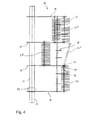
- individual clubs are not shown per racket bolt. Of course, however, it is at least for a normal grinding operation advantageous if the rotor is completely equipped with rackets (in the present embodiment: 11 or 12 rackets per racket bolt; FIG. 4 ).
- the present rotor 1 has, for example, three segments with 24 batons and - if fully loaded - 284 or 288 clubs.
- Each segment 15, 15 ' are each assigned two support rings 16.
- the support rings 16 have a reduced outer diameter in the region of the racket bolts of the adjacent segments, so that the racket bolt of an adjacent segment is not obstructed by the support rings 16 when being pulled out.
- a stable and robust construction is achieved by the support rings 16 are connected by means of support bolts 17 with the rotor disks 18, 12.
- the support bolts 17 extend over the entire length of the rotor and thus include all segments 15, 15 '.
- FIG. 3a a single racket bolt 20 is shown in a first embodiment.
- the racket pin 20 consists of a cylindrical shaft with an outer diameter D a .
- a cap 24 is arranged frontally.
- the cap 24 has a the outer diameter D a of the racket pin 20 corresponding hole.
- the cap 24 is fixed to the racquet bolt 20 via a fastening screw 29.
- another screw or other types of attachment could be selected.
- the racket pin 20 could have a corresponding external thread on the face side and the bore 26 could have a corresponding internal thread.
- the cap 24 has a cylindrical portion with an outer diameter d i , which corresponds to the opening 13 in the rotor disk 12.
- the cap 24 is supported on one side by a shoulder 25 predetermining circumferential collar.
- a groove 30 is arranged in the cap, into which a (in FIG. 3a in a plan view shown and designated 28) retaining ring, in particular a snap ring, can be used.
- the difference between the two diameters d i and D a results in the extraction of the racket pin 20 from the opening 13 an annular gap, which allows tilting for easy removal.
- FIG. 3b shows a racket bolt 20 'in another embodiment.
- the racquet bolt in turn consists of a cylindrical shaft with an outer diameter D a (compare this FIG. 3a ).
- a cap 24, 24 ' In contrast to the embodiment according to FIG. 3a is at both ends of the racket pin a cap 24, 24 'arranged frontally. These two caps 24, 24 ', in turn, have a bore 26, 26' corresponding to the outer diameter D a of the club pin.
- the cap 24 is identical to FIG.
- the racquet bolt 20 has a circumferential groove 34 which receives the snap ring 28 'and in a groove 30' in the bore 26 'of the cap 24' can be latched. It goes without saying that for the two types of attachment of the caps 24, 24 'on the bat 20 also other variants, such as FIG. 3a described, are possible. Both caps 24, 24 'in turn have a cylindrical portion with an outer diameter d i (see. FIG. 3a ), which corresponds to the opening 13 in the rotor disk 12.
- the one cap 24 again has on one side a shoulder forming a shoulder 25, while the other cap 24 'is firmly fixed in the opening 13 of the rotor 12.
- the cap 24 ' may be glued, welded or screwed.
- each racket bolt 20, 20 'and 20 "receives between each two adjacent support rings 16 and between a support ring 16 and an adjacent rotor disk 12, 12', 18, 19 a plurality of rackets 23.
- the racket pin 20 To disassemble, for example, to replace the rackets, the racket pin 20 must be pulled out of the opening 13 in the rotor disk 12. However, because of the adjacent rotor disk 12 ', the racket bolt 20 can not be pulled out completely in the axial direction. Because of the larger diameter d i (see. FIG. 3a ) of the opening 13 in comparison to the outer diameter D a (see. FIG. 3a ) of the racket pin 20 tilting is possible, can still be removed after tilting the racket bolt in a simple manner from the rotor. Such a tipped clubstick is shown in dashed lines and designated 20 *.
- the support rings 16 have in The area of the club pins 20, 20 'and 20 "of the adjacent segments has a reduced outer diameter so that the club pin of an adjacent segment will not be obstructed during withdrawal by the support rings 16.
- the individual rotor disks 12, 12', 18 and 19 are at regular intervals arranged on the rotor shaft 11 and connected via flange-like holding body 32 each fixed to the rotor shaft 11.
- FIG. 5 relates to a second variant of a rotor 10 according to the invention, which is also characterized by a segment-like structure.
- This rotor 10 differs from the previous embodiment substantially in that no single racket 23, but whole racket packs 32 are received between adjacent rotor disks.
- Such a racquet package 32 is in FIG. 6 shown.
- the racquet package 32 approximately triangular support body 31, which serve to stabilize.
- the racket packs 32 also have a rake 33.
- This rake 33 serves as previously described the lateral guidance and positioning of the rackets.
- a dismantled racquet bolt 20 can be seen.
- This racket bolt 20 forms a unit together with the cap 24.
- each racket 23 two circular recesses are provided. The second recess makes it possible that in case of signs of wear, the racket can be mounted in the reverse position on the racket package and so on.
- FIG. 7 a perspective view of a locking device 40 is shown.
- the locking device 40 has in Essentially a base frame 46, a lever 48 and an engagement means 44 on.
- a retaining means 41 in the form of a hook 42 and a paragraph 43 is arranged.
- the locking device 40 can be hung in the grinding chamber of a hammer mill on a suitably designed backdrop.
- the engagement means 44 can be moved over the knee lever 49, which leads to a clamping of a rotor disk and thus fixation of the rotor with a suitable arrangement in the grinding chamber.
- FIGS. 8a and 8b show the function of the locking device 40 according to FIG. 7 with respect to a rotor disk 12 in a schematic side view. It shows the FIG. 8a the locking device 40 in a rest position while FIG. 8b the locking device 40 in a locking position shows.
- the locking device 40 is hooked with its hook 42 on a wear rail 50 of the grinding chamber of the hammer mill.
- the paragraph 43 serves to protect against accidental release.
- the lever 48 By means of the lever 48, the knee lever 49 can be moved, which in turn leads to a displacement of the engagement means 44.
- the engagement means 44 can thus from a rest position (see. FIG. 8a ) in a locking position (see. FIG.
- a clamping plate 45 arranged on the engagement means 44 is pressed onto an edge of a rotor disk 12.
- the clamping plate 45 is made of a hard rubber, so that during the clamping the rotor disk 12 is not damaged but still an optimal fixation of the rotor disk 12 is ensured.
- Other materials of the clamping plate 45 are conceivable.
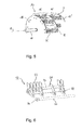
- FIG. 9 shows in a perspective view of an embodiment of a collecting device 35 according to the invention.
- the collecting device 35 essentially has a trough-shaped Collection chamber 36, which is provided with two handles 38 and three hook-shaped fasteners 37.
- the collecting space 36 and the fastening elements 37 of the collecting device 35 are integrally formed as a sheet metal bent part. Another embodiment is also conceivable.
- FIG. 10 is a schematic side view of a collecting device 35 and a rotor 10 is shown.
- the rotor 10 is simplified and only the essential elements are shown.
- the rotor 10 has a rotor shaft 11. On the shaft, a rotor disk 12 is fixed. Also, a support ring 16 is shown.
- the collecting device 35 is fastened with its fastening elements on the rake 33. In this case, the collecting device 35 is arranged so that the racket 23 is located directly above the collecting space of the collecting device 35.
- the handle 38 which allows easy positioning of the catcher 35.
- FIGS. 12 and 13 each show a detailed view of the sliding door mechanism with upper rollers 4 'in different positions.
- the door 3 is in a closed position.
- a compression means 7 designed as a helical compression spring or a spring assembly is compressed, which results in a prestress.
- the rollers 4 ' are biased on the roller axes 6 by the pressure means 7 in the open position. Moving out of the closed position is thus facilitated.
- FIG. 13 shows the door 3 FIG. 12 in open position (relaxed position).
Landscapes
- Engineering & Computer Science (AREA)
- Food Science & Technology (AREA)
- Crushing And Pulverization Processes (AREA)
- Constituent Portions Of Griding Lathes, Driving, Sensing And Control (AREA)
- Percussive Tools And Related Accessories (AREA)
Priority Applications (1)
| Application Number | Priority Date | Filing Date | Title |
|---|---|---|---|
| EP12176563.0A EP2514530A3 (fr) | 2010-01-15 | 2011-01-07 | Fragmenteuse, rotor dýune fragmenteuse, boulon de percussion, ainsi que dispositif collecteur et dispositif de fixation |
Applications Claiming Priority (3)
| Application Number | Priority Date | Filing Date | Title |
|---|---|---|---|
| EP10150863A EP2345479A1 (fr) | 2010-01-15 | 2010-01-15 | Fragmenteuse, rotor d'une fragmenteuse, boulon de percussion, ainsi que dispositif collecteur et dispositif de fixation |
| EP11700123.0A EP2421653B1 (fr) | 2010-01-15 | 2011-01-07 | Fragmenteuse, rotor d'une fragmenteuse, boulon de percussion, ainsi que dispositif collecteur et dispositif de fixation |
| EP12176563.0A EP2514530A3 (fr) | 2010-01-15 | 2011-01-07 | Fragmenteuse, rotor dýune fragmenteuse, boulon de percussion, ainsi que dispositif collecteur et dispositif de fixation |
Related Parent Applications (2)
| Application Number | Title | Priority Date | Filing Date |
|---|---|---|---|
| EP11700123.0A Division EP2421653B1 (fr) | 2010-01-15 | 2011-01-07 | Fragmenteuse, rotor d'une fragmenteuse, boulon de percussion, ainsi que dispositif collecteur et dispositif de fixation |
| EP11700123.0 Division | 2011-01-07 |
Publications (2)
| Publication Number | Publication Date |
|---|---|
| EP2514530A2 true EP2514530A2 (fr) | 2012-10-24 |
| EP2514530A3 EP2514530A3 (fr) | 2013-04-10 |
Family
ID=42691152
Family Applications (3)
| Application Number | Title | Priority Date | Filing Date |
|---|---|---|---|
| EP10150863A Withdrawn EP2345479A1 (fr) | 2010-01-15 | 2010-01-15 | Fragmenteuse, rotor d'une fragmenteuse, boulon de percussion, ainsi que dispositif collecteur et dispositif de fixation |
| EP12176563.0A Withdrawn EP2514530A3 (fr) | 2010-01-15 | 2011-01-07 | Fragmenteuse, rotor dýune fragmenteuse, boulon de percussion, ainsi que dispositif collecteur et dispositif de fixation |
| EP11700123.0A Active EP2421653B1 (fr) | 2010-01-15 | 2011-01-07 | Fragmenteuse, rotor d'une fragmenteuse, boulon de percussion, ainsi que dispositif collecteur et dispositif de fixation |
Family Applications Before (1)
| Application Number | Title | Priority Date | Filing Date |
|---|---|---|---|
| EP10150863A Withdrawn EP2345479A1 (fr) | 2010-01-15 | 2010-01-15 | Fragmenteuse, rotor d'une fragmenteuse, boulon de percussion, ainsi que dispositif collecteur et dispositif de fixation |
Family Applications After (1)
| Application Number | Title | Priority Date | Filing Date |
|---|---|---|---|
| EP11700123.0A Active EP2421653B1 (fr) | 2010-01-15 | 2011-01-07 | Fragmenteuse, rotor d'une fragmenteuse, boulon de percussion, ainsi que dispositif collecteur et dispositif de fixation |
Country Status (8)
| Country | Link |
|---|---|
| US (1) | US8608099B2 (fr) |
| EP (3) | EP2345479A1 (fr) |
| CN (2) | CN102711996B (fr) |
| BR (1) | BR112012017524A2 (fr) |
| DK (1) | DK2421653T3 (fr) |
| ES (1) | ES2442774T3 (fr) |
| PL (1) | PL2421653T3 (fr) |
| WO (1) | WO2011086035A2 (fr) |
Cited By (1)
| Publication number | Priority date | Publication date | Assignee | Title |
|---|---|---|---|---|
| CN103521327A (zh) * | 2013-10-28 | 2014-01-22 | 江苏大唐机械有限公司 | 锤式再破机 |
Families Citing this family (8)
| Publication number | Priority date | Publication date | Assignee | Title |
|---|---|---|---|---|
| EP2345479A1 (fr) * | 2010-01-15 | 2011-07-20 | Bühler AG | Fragmenteuse, rotor d'une fragmenteuse, boulon de percussion, ainsi que dispositif collecteur et dispositif de fixation |
| CN106799296A (zh) * | 2017-03-13 | 2017-06-06 | 江苏宝山重型机械制造有限公司 | 一种多功能反击式破碎机 |
| CN107790228B (zh) * | 2017-10-13 | 2023-02-10 | 江苏徐工工程机械研究院有限公司 | 一种反击式破碎机、其转子定位系统和转子定位方法 |
| KR101870415B1 (ko) * | 2018-02-23 | 2018-06-22 | 최용희 | 전자 폐기물 재활용을 위한 파쇄 장치 |
| CN209109274U (zh) * | 2018-08-30 | 2019-07-16 | 北京百旺环境科技股份有限公司 | 一种制砂机下篦板及制砂机 |
| MX2024006499A (es) | 2021-12-16 | 2024-06-05 | Buehler Ag | Jaula de martillo. |
| WO2023152125A1 (fr) | 2022-02-09 | 2023-08-17 | Bühler AG | Broyeur à marteaux conçu de manière modulaire |
| WO2024006314A1 (fr) * | 2022-06-28 | 2024-01-04 | Oscar Andrew | Systèmes et procédés de traitement de chanvre |
Citations (1)
| Publication number | Priority date | Publication date | Assignee | Title |
|---|---|---|---|---|
| DE10253345A1 (de) | 2002-11-14 | 2004-05-27 | H.-I. Pallmann Innovation Gmbh & Co. | Vorrichtung zur Erleichterung der Hammermühlenwartung |
Family Cites Families (14)
| Publication number | Priority date | Publication date | Assignee | Title |
|---|---|---|---|---|
| US3346201A (en) * | 1964-02-03 | 1967-10-10 | Sr Donald F Butler | Aggregate manufacturing machine |
| DE2436338C3 (de) * | 1974-07-27 | 1980-08-21 | Hazemag Dr. E. Andreas Gmbh & Co, 4400 Muenster | Rotor für Hammermühlen |
| GB2017532B (en) * | 1977-11-19 | 1982-03-24 | Parker Ltd F | Crushing mechanism |
| FR2448936A1 (fr) * | 1979-02-16 | 1980-09-12 | Gondard Sa | Broyeur industriel a ordures menageres |
| US4504019A (en) * | 1982-03-03 | 1985-03-12 | Newell Manufacturing Company | Hammer mill having capped disc rotor |
| DE19756275C1 (de) * | 1997-12-18 | 1999-06-02 | Svedala Lindemann Gmbh | Rotor für eine Zerkleinerungsmaschine |
| US7175106B2 (en) * | 2001-03-25 | 2007-02-13 | Roman Kendyl A | Paint striper and methods of construction |
| US7325761B2 (en) * | 2004-05-18 | 2008-02-05 | Alstom Technology Ltd | Hammer for a material size reduction machine |
| US7140569B2 (en) * | 2004-08-11 | 2006-11-28 | Young Roger T | Forged hammermill hammer |
| US7753302B2 (en) * | 2005-12-08 | 2010-07-13 | Swissrtec Gmbh | Rotor for an impact crusher |
| CN201012332Y (zh) * | 2006-05-26 | 2008-01-30 | 布勒(常州)机械有限公司 | 立式转子粉碎机 |
| JP2008000656A (ja) * | 2006-06-21 | 2008-01-10 | Fuji Kogyo Co Ltd | 破砕装置 |
| CN101549310A (zh) * | 2009-04-30 | 2009-10-07 | 浙江杭钻机械制造股份有限公司 | 一种箱体带门的破碎机 |
| EP2345479A1 (fr) * | 2010-01-15 | 2011-07-20 | Bühler AG | Fragmenteuse, rotor d'une fragmenteuse, boulon de percussion, ainsi que dispositif collecteur et dispositif de fixation |
-
2010
- 2010-01-15 EP EP10150863A patent/EP2345479A1/fr not_active Withdrawn
-
2011
- 2011-01-07 EP EP12176563.0A patent/EP2514530A3/fr not_active Withdrawn
- 2011-01-07 EP EP11700123.0A patent/EP2421653B1/fr active Active
- 2011-01-07 US US13/521,826 patent/US8608099B2/en not_active Expired - Fee Related
- 2011-01-07 CN CN201180005921.1A patent/CN102711996B/zh not_active Expired - Fee Related
- 2011-01-07 WO PCT/EP2011/050159 patent/WO2011086035A2/fr not_active Ceased
- 2011-01-07 ES ES11700123.0T patent/ES2442774T3/es active Active
- 2011-01-07 BR BR112012017524A patent/BR112012017524A2/pt not_active IP Right Cessation
- 2011-01-07 CN CN201410670488.9A patent/CN104525312B/zh not_active Expired - Fee Related
- 2011-01-07 DK DK11700123.0T patent/DK2421653T3/da active
- 2011-01-07 PL PL11700123T patent/PL2421653T3/pl unknown
Patent Citations (1)
| Publication number | Priority date | Publication date | Assignee | Title |
|---|---|---|---|---|
| DE10253345A1 (de) | 2002-11-14 | 2004-05-27 | H.-I. Pallmann Innovation Gmbh & Co. | Vorrichtung zur Erleichterung der Hammermühlenwartung |
Cited By (1)
| Publication number | Priority date | Publication date | Assignee | Title |
|---|---|---|---|---|
| CN103521327A (zh) * | 2013-10-28 | 2014-01-22 | 江苏大唐机械有限公司 | 锤式再破机 |
Also Published As
| Publication number | Publication date |
|---|---|
| US8608099B2 (en) | 2013-12-17 |
| CN104525312B (zh) | 2017-11-17 |
| PL2421653T3 (pl) | 2014-04-30 |
| US20120286082A1 (en) | 2012-11-15 |
| DK2421653T3 (da) | 2014-01-27 |
| EP2345479A1 (fr) | 2011-07-20 |
| BR112012017524A2 (pt) | 2019-09-24 |
| WO2011086035A2 (fr) | 2011-07-21 |
| EP2421653B1 (fr) | 2013-10-30 |
| CN102711996B (zh) | 2014-12-24 |
| WO2011086035A3 (fr) | 2011-10-13 |
| EP2421653A2 (fr) | 2012-02-29 |
| CN104525312A (zh) | 2015-04-22 |
| CN102711996A (zh) | 2012-10-03 |
| ES2442774T3 (es) | 2014-02-13 |
| EP2514530A3 (fr) | 2013-04-10 |
Similar Documents
| Publication | Publication Date | Title |
|---|---|---|
| EP2421653B1 (fr) | Fragmenteuse, rotor d'une fragmenteuse, boulon de percussion, ainsi que dispositif collecteur et dispositif de fixation | |
| EP2012927B1 (fr) | Dispositif de desintegration | |
| DE102009034457B4 (de) | Rotor einer Zerkleinerungsmaschine | |
| DE2357176A1 (de) | Vorrichtung zum schneiden von stroh und dergl | |
| DE202006007055U1 (de) | Schlegel für eine Zerkleinerungsvorrichtung | |
| DE2448814B2 (de) | Vorrichtung zur stanzdruckregulierung einer tiegelstanzpresse sowie zur justierung der tiegel zueinander | |
| EP0058781A1 (fr) | Cylindre extracteur pour des balles de matières fibreuses | |
| DE102008010675B4 (de) | Fangvorrichtung zum Stillsetzen einer Umlenk- oder Wickelwelle | |
| DE102014213048B4 (de) | Hammermühle | |
| DE4124855C2 (de) | Stiftmühle | |
| DE102007010907B4 (de) | Zellenradschleuse | |
| DE3744241C2 (fr) | ||
| DE3004452C3 (de) | Furchenöffner für Sä- oder Pflanzmaschinen | |
| EP0404100B1 (fr) | Palier d'un rouleau dans un châssis, notamment d'un rouleau diviseur dans une presse à balle rondes | |
| DE3822552C2 (de) | Aufnahmebolzen für Hammermühlenschläger | |
| DE202010017214U1 (de) | Hammermühle und Rotor einer Hammermühle | |
| DE2909000C2 (de) | Scheibenradhäcksler | |
| DE10253345B4 (de) | Vorrichtung zur Erleichterung der Hammermühlenwartung | |
| EP3485721B1 (fr) | Dispositif de fléau pour un arbre de broyeur de paille doté d'une ouverture de fixation dans une console et arbre de broyeur de paille | |
| DE2633012C2 (de) | Hammerbrecher | |
| EP2009180B1 (fr) | Appareil de démoulage pour un rouleau compresseur | |
| DE3121007A1 (de) | Kurbelantriebsvorrichtung fuer bodenverdichtungsgeraete | |
| DE4410309C2 (de) | Schlagwalzenbrecher | |
| EP3871486A1 (fr) | Unité de fléaux | |
| CH665569A5 (de) | Schlaegeraufhaengung von hammermuehlen. |
Legal Events
| Date | Code | Title | Description |
|---|---|---|---|
| PUAI | Public reference made under article 153(3) epc to a published international application that has entered the european phase |
Free format text: ORIGINAL CODE: 0009012 |
|
| AC | Divisional application: reference to earlier application |
Ref document number: 2421653 Country of ref document: EP Kind code of ref document: P |
|
| AK | Designated contracting states |
Kind code of ref document: A2 Designated state(s): AL AT BE BG CH CY CZ DE DK EE ES FI FR GB GR HR HU IE IS IT LI LT LU LV MC MK MT NL NO PL PT RO RS SE SI SK SM TR |
|
| AX | Request for extension of the european patent |
Extension state: BA ME |
|
| RIN1 | Information on inventor provided before grant (corrected) |
Inventor name: TOBLER, MARCO Inventor name: HABLUETZEL, WALTER |
|
| RIC1 | Information provided on ipc code assigned before grant |
Ipc: B02C 13/282 20060101ALI20121113BHEP Ipc: B02C 13/28 20060101AFI20121113BHEP Ipc: B02C 13/04 20060101ALI20121113BHEP |
|
| PUAL | Search report despatched |
Free format text: ORIGINAL CODE: 0009013 |
|
| AK | Designated contracting states |
Kind code of ref document: A3 Designated state(s): AL AT BE BG CH CY CZ DE DK EE ES FI FR GB GR HR HU IE IS IT LI LT LU LV MC MK MT NL NO PL PT RO RS SE SI SK SM TR |
|
| AX | Request for extension of the european patent |
Extension state: BA ME |
|
| RIC1 | Information provided on ipc code assigned before grant |
Ipc: B02C 13/28 20060101AFI20130305BHEP Ipc: B02C 13/04 20060101ALI20130305BHEP Ipc: B02C 13/282 20060101ALI20130305BHEP |
|
| 17P | Request for examination filed |
Effective date: 20130725 |
|
| RBV | Designated contracting states (corrected) |
Designated state(s): AL AT BE BG CH CY CZ DE DK EE ES FI FR GB GR HR HU IE IS IT LI LT LU LV MC MK MT NL NO PL PT RO RS SE SI SK SM TR |
|
| STAA | Information on the status of an ep patent application or granted ep patent |
Free format text: STATUS: THE APPLICATION HAS BEEN WITHDRAWN |
|
| 18W | Application withdrawn |
Effective date: 20170724 |