EP2514541A2 - Dispositif et procédé de fabrication d'un compact vert à partir d'une matière active sous forme de poudre ou de granulés - Google Patents
Dispositif et procédé de fabrication d'un compact vert à partir d'une matière active sous forme de poudre ou de granulés Download PDFInfo
- Publication number
- EP2514541A2 EP2514541A2 EP12154456A EP12154456A EP2514541A2 EP 2514541 A2 EP2514541 A2 EP 2514541A2 EP 12154456 A EP12154456 A EP 12154456A EP 12154456 A EP12154456 A EP 12154456A EP 2514541 A2 EP2514541 A2 EP 2514541A2
- Authority
- EP
- European Patent Office
- Prior art keywords
- filling
- filling shoe
- shoe
- parking position
- movement
- Prior art date
- Legal status (The legal status is an assumption and is not a legal conclusion. Google has not performed a legal analysis and makes no representation as to the accuracy of the status listed.)
- Withdrawn
Links
- 239000008187 granular material Substances 0.000 title claims abstract description 22
- 238000004519 manufacturing process Methods 0.000 title abstract description 8
- 239000000843 powder Substances 0.000 title description 2
- 239000000463 material Substances 0.000 claims description 114
- 230000006835 compression Effects 0.000 claims description 13
- 238000007906 compression Methods 0.000 claims description 13
- 238000000034 method Methods 0.000 claims description 11
- 238000010276 construction Methods 0.000 abstract description 11
- 239000012254 powdered material Substances 0.000 abstract description 11
- 239000011159 matrix material Substances 0.000 abstract description 4
- 238000005520 cutting process Methods 0.000 description 34
- 238000005429 filling process Methods 0.000 description 18
- 239000002245 particle Substances 0.000 description 18
- 238000003825 pressing Methods 0.000 description 9
- 238000012545 processing Methods 0.000 description 6
- 238000009826 distribution Methods 0.000 description 3
- 238000003754 machining Methods 0.000 description 3
- 238000003860 storage Methods 0.000 description 3
- 238000005056 compaction Methods 0.000 description 2
- 238000011161 development Methods 0.000 description 2
- 230000018109 developmental process Effects 0.000 description 2
- 238000005245 sintering Methods 0.000 description 2
- 241001522319 Chloris chloris Species 0.000 description 1
- 238000007792 addition Methods 0.000 description 1
- 230000001419 dependent effect Effects 0.000 description 1
- 238000013461 design Methods 0.000 description 1
- 229910003460 diamond Inorganic materials 0.000 description 1
- 239000010432 diamond Substances 0.000 description 1
- 238000006073 displacement reaction Methods 0.000 description 1
- 230000000694 effects Effects 0.000 description 1
- 150000002148 esters Chemical class 0.000 description 1
- 238000012986 modification Methods 0.000 description 1
- 230000004048 modification Effects 0.000 description 1
- 239000007787 solid Substances 0.000 description 1
- 238000009827 uniform distribution Methods 0.000 description 1
- 238000003466 welding Methods 0.000 description 1
Images
Classifications
-
- B—PERFORMING OPERATIONS; TRANSPORTING
- B30—PRESSES
- B30B—PRESSES IN GENERAL
- B30B11/00—Presses specially adapted for forming shaped articles from material in particulate or plastic state, e.g. briquetting presses, tabletting presses
- B30B11/02—Presses specially adapted for forming shaped articles from material in particulate or plastic state, e.g. briquetting presses, tabletting presses using a ram exerting pressure on the material in a moulding space
- B30B11/027—Particular press methods or systems
-
- B—PERFORMING OPERATIONS; TRANSPORTING
- B22—CASTING; POWDER METALLURGY
- B22F—WORKING METALLIC POWDER; MANUFACTURE OF ARTICLES FROM METALLIC POWDER; MAKING METALLIC POWDER; APPARATUS OR DEVICES SPECIALLY ADAPTED FOR METALLIC POWDER
- B22F3/00—Manufacture of workpieces or articles from metallic powder characterised by the manner of compacting or sintering; Apparatus specially adapted therefor ; Presses and furnaces
- B22F3/02—Compacting only
- B22F3/03—Press-moulding apparatus therefor
-
- B—PERFORMING OPERATIONS; TRANSPORTING
- B21—MECHANICAL METAL-WORKING WITHOUT ESSENTIALLY REMOVING MATERIAL; PUNCHING METAL
- B21D—WORKING OR PROCESSING OF SHEET METAL OR METAL TUBES, RODS OR PROFILES WITHOUT ESSENTIALLY REMOVING MATERIAL; PUNCHING METAL
- B21D22/00—Shaping without cutting, by stamping, spinning, or deep-drawing
- B21D22/20—Deep-drawing
- B21D22/22—Deep-drawing with devices for holding the edge of the blanks
-
- B—PERFORMING OPERATIONS; TRANSPORTING
- B22—CASTING; POWDER METALLURGY
- B22F—WORKING METALLIC POWDER; MANUFACTURE OF ARTICLES FROM METALLIC POWDER; MAKING METALLIC POWDER; APPARATUS OR DEVICES SPECIALLY ADAPTED FOR METALLIC POWDER
- B22F3/00—Manufacture of workpieces or articles from metallic powder characterised by the manner of compacting or sintering; Apparatus specially adapted therefor ; Presses and furnaces
- B22F3/004—Filling molds with powder
-
- B—PERFORMING OPERATIONS; TRANSPORTING
- B30—PRESSES
- B30B—PRESSES IN GENERAL
- B30B11/00—Presses specially adapted for forming shaped articles from material in particulate or plastic state, e.g. briquetting presses, tabletting presses
- B30B11/005—Control arrangements
-
- B—PERFORMING OPERATIONS; TRANSPORTING
- B30—PRESSES
- B30B—PRESSES IN GENERAL
- B30B15/00—Details of, or accessories for, presses; Auxiliary measures in connection with pressing
- B30B15/04—Frames; Guides
-
- B—PERFORMING OPERATIONS; TRANSPORTING
- B30—PRESSES
- B30B—PRESSES IN GENERAL
- B30B15/00—Details of, or accessories for, presses; Auxiliary measures in connection with pressing
- B30B15/30—Feeding material to presses
- B30B15/302—Feeding material in particulate or plastic state to moulding presses
- B30B15/304—Feeding material in particulate or plastic state to moulding presses by using feed frames or shoes with relative movement with regard to the mould or moulds
- B30B15/306—Feeding material in particulate or plastic state to moulding presses by using feed frames or shoes with relative movement with regard to the mould or moulds for multi-layer articles
-
- C—CHEMISTRY; METALLURGY
- C04—CEMENTS; CONCRETE; ARTIFICIAL STONE; CERAMICS; REFRACTORIES
- C04B—LIME, MAGNESIA; SLAG; CEMENTS; COMPOSITIONS THEREOF, e.g. MORTARS, CONCRETE OR LIKE BUILDING MATERIALS; ARTIFICIAL STONE; CERAMICS; REFRACTORIES; TREATMENT OF NATURAL STONE
- C04B35/00—Shaped ceramic products characterised by their composition; Ceramics compositions; Processing powders of inorganic compounds preparatory to the manufacturing of ceramic products
- C04B35/622—Forming processes; Processing powders of inorganic compounds preparatory to the manufacturing of ceramic products
- C04B35/626—Preparing or treating the powders individually or as batches ; preparing or treating macroscopic reinforcing agents for ceramic products, e.g. fibres; mechanical aspects section B
- C04B35/62605—Treating the starting powders individually or as mixtures
-
- C—CHEMISTRY; METALLURGY
- C04—CEMENTS; CONCRETE; ARTIFICIAL STONE; CERAMICS; REFRACTORIES
- C04B—LIME, MAGNESIA; SLAG; CEMENTS; COMPOSITIONS THEREOF, e.g. MORTARS, CONCRETE OR LIKE BUILDING MATERIALS; ARTIFICIAL STONE; CERAMICS; REFRACTORIES; TREATMENT OF NATURAL STONE
- C04B2235/00—Aspects relating to ceramic starting mixtures or sintered ceramic products
- C04B2235/02—Composition of constituents of the starting material or of secondary phases of the final product
- C04B2235/30—Constituents and secondary phases not being of a fibrous nature
- C04B2235/42—Non metallic elements added as constituents or additives, e.g. sulfur, phosphor, selenium or tellurium
- C04B2235/422—Carbon
- C04B2235/427—Diamond
-
- C—CHEMISTRY; METALLURGY
- C04—CEMENTS; CONCRETE; ARTIFICIAL STONE; CERAMICS; REFRACTORIES
- C04B—LIME, MAGNESIA; SLAG; CEMENTS; COMPOSITIONS THEREOF, e.g. MORTARS, CONCRETE OR LIKE BUILDING MATERIALS; ARTIFICIAL STONE; CERAMICS; REFRACTORIES; TREATMENT OF NATURAL STONE
- C04B2235/00—Aspects relating to ceramic starting mixtures or sintered ceramic products
- C04B2235/60—Aspects relating to the preparation, properties or mechanical treatment of green bodies or pre-forms
- C04B2235/604—Pressing at temperatures other than sintering temperatures
-
- Y—GENERAL TAGGING OF NEW TECHNOLOGICAL DEVELOPMENTS; GENERAL TAGGING OF CROSS-SECTIONAL TECHNOLOGIES SPANNING OVER SEVERAL SECTIONS OF THE IPC; TECHNICAL SUBJECTS COVERED BY FORMER USPC CROSS-REFERENCE ART COLLECTIONS [XRACs] AND DIGESTS
- Y10—TECHNICAL SUBJECTS COVERED BY FORMER USPC
- Y10S—TECHNICAL SUBJECTS COVERED BY FORMER USPC CROSS-REFERENCE ART COLLECTIONS [XRACs] AND DIGESTS
- Y10S100/00—Presses
- Y10S100/903—Pelleters
Definitions
- the present invention relates to an apparatus for producing a green compact from a powdery or granular material according to the preamble of claim 1 and a method for producing a green compact from a powdery or granular material according to the preamble of claim 6.
- Known processing tools such as drill bits and circular saw blades, consist of a main body, which is connected to cutting segments.
- the cutting segments are connected, for example, by laser welding to the main body and consist of a foot zone and a working zone.
- the foot zone is the area of the cutting segment which is connected to the main body of the machining tool, and the remaining cutting segment is the useful zone.
- the foot zone consists for example of a weldable material in order to weld the main body and the cutting segments well.
- the useful zone consists of a base material and cutting particles embedded in the base material.
- the cutting particles are formed as diamond particles or other abrasive particles that are suitable for abrasive machining. The cutting action is carried out by the cutting particles, the base material serves to fix the cutting particles.
- the cutting segments are produced in a two-stage process from powdered or granular materials: In a first stage, a green compact is built up of superimposed layers of material and in a second stage, the green compact is finished in a sintering plant by temperature and / or pressure. In a first group of manufacturing processes, the cutting particles are mixed into the base material and evenly distributed in the base material. The disadvantage is that cutting particle esters can form which reduce the cutting performance and the service life of the cutting segments. In a second group of manufacturing processes, the base material is applied in layers with a filling shoe and the cutting particles are placed in the base material by a setting unit in a separate setting step. By the separate Setting step, the concentration and distribution of the cutting particles in the material layer can be varied and adapted to the machining task.
- Known devices for producing a green body from a powdery or granular material by successive application and compression of the material consist of a filling shoe, which is filled with the material or a plurality of materials and is adjustable by means of an adjustment, a die with at least one build-up chamber, which the filling shoe in layers filled with the material, and a press with a lower punch and a punch, which are adjustable by means of a height adjustment and compress the layered material deposited in the buildup chamber.
- a first parking position is provided, in which the filling shoe is arranged during the pressing process.
- the fill shoe is moved from the parking position into an end position in which the fill shoe is opened and material is filled into the build-up chamber.
- the filling shoe is closed. This position is referred to as the second end position for the filling shoe.
- the filling shoe is moved back to the parking position after the filling operation from the second end position via the first end position.
- the filling shoe can be moved in different directions of movement over the die or over the build-up chambers in order to reduce one-sided compression.
- the problem with this solution is that the movements increase the complexity of the machine and additional machine components are required.
- the object of the present invention is to provide an apparatus and a method for producing a green compact from a powdery or granular material Layer by layer application and compression of the material to further develop so that the cutting segments without additional machine components have a uniform material density.
- the necessary time to build the green compacts should be reduced.
- the invention provides that a second parking position is provided for the filling shoe, wherein the second parking position is different from the first parking position.
- a second parking position is provided for the filling shoe, the direction of movement of the filling shoe can be maintained after the filling operation. The filling shoe does not first have to be slowed down and then accelerated in the opposite direction of movement. If the filling shoe moved back into its parking position after the filling process, the path over the matrix would have to be additionally covered.
- the direction of movement in which the material is applied can be reversed in successive layers of material, without a second filling shoe is required.
- the filling shoe in the first and / or second parking position with a filling station which fills the filling shoe with material connectable.
- the non-productive time in which the filling shoe is arranged in a parking position, is used to fill the filling shoe with material.
- the filling shoe can be made smaller, since the filling shoe can be regularly filled with material. If a filling station is not provided for the filling shoe, the filling shoe must be filled with a large amount of material or connected to a storage container via supply lines. The movement of the filling shoe can lead to a disconnection of the supply lines, so that the material supply is disturbed or interrupted.
- the filling shoe is connectable in the first parking position with a first filling station and in the second parking position with a second filling station.
- the idle time in which the filling shoe is arranged in a parking position, can be better utilized.
- a first material at the first filling station and a second material at the second filling station can be filled.
- the fact that only one material is filled at each filling station, the filling system is designed structurally simpler. Each filling station only has to be connected to the storage container via a supply line.
- a first and second material can be filled at the first and second filling stations.
- the speed of the filling shoe is adjustable via the adjusting device.
- the adjustability of the speed with which the filling shoe is moved can be used to increase the speed of positioning the filling shoe against a constant feed rate between the first and second end position of the filling process. Higher positioning speeds can reduce the non-productive time needed to build the green compacts.
- the adjusting device of the filling shoe is particularly preferably designed as an electric motor.
- the speed with which the filling shoe is moved over the worktop is adjustable via a control device.
- the filling shoe is moved from a parking position to an end position or from an end position to a parking position at a higher speed than during the filling process.
- the feed rate during the filling process depends mainly on the filling behavior of the material.
- the filling shoe is moved after the application of the material from the second end position to a second parking position, wherein the second parking position is different from the first parking position.
- the positioning of the filling shoe is reduced. If the filling shoe moved back into its parking position after the filling process, the path over the matrix would have to be additionally covered.
- the material is applied in a material layer in a first direction of movement and in a following further material layer in a second direction of movement, wherein the first and second directions of movement are directed opposite to each other.
- a compression zone with increased material density is formed in the end region of the material layer during the filling process.
- the speed with which the filling shoe is moved between the parking position and the end position is preferably increased at least in sections compared to a constant speed of the filling shoe between the end positions. Higher speeds when positioning the filling shoe can reduce the non-productive time of the green compacts and thus the time required to build up the green compacts.
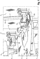
- Fig. 1 shows an inventive device 1 for producing a green compact from a powdered or granular material by successive application and compression of the material.
- the device 1 comprises a machine frame 2 , a horizontally arranged worktop 3 with a die 4 , a filling shoe 5 and a press 6 with a lower punch 7 and an upper punch 8 .
- the die 4 is arranged interchangeably in the work surface 3 and comprises a first build-up chamber 9A for a first green compact and a second build-up chamber 9B for a second green compact.
- the construction chambers 9A, 9B are formed as passage openings in the die 4, in which the lower punch 7 and the upper punch 8 can engage.
- the build-up chambers 9A, 9B are filled layer by layer with the material during the construction of the green compacts.
- the geometry of the build-up chambers 9A, 9B corresponds to the desired geometry of the cutting segments, wherein shrinkage effects are to be considered during sintering of the green compacts.
- construction chambers 9A, 9B are identical, so that identical cutting segments are produced.
- the construction chambers can also be designed differently.
- the filling shoe 5 for applying the material into the build-up chambers 9A, 9B is arranged above the work surface 3.
- the filling shoe 5 is attached to a support arm 10 and adjustable by means of an adjusting device 11 on the top of the worktop 3.
- the adjusting device 11 is designed as a pivoting device which moves the filling shoe 5 about a pivot axis 12 .
- the adjusting device can be designed as a linear drive or as a combined drive unit.
- the green body is constructed of powdered or granular material in several layers.
- the green compact can be constructed from the same material or from different materials.
- the foot zone of a cutting segment i. the region of the cutting segment which is connected to the main body, be constructed of a weldable material to weld the cutting segment and the main body well.
- the rest of the cutting segment consists of a wear material, in which the cutting particles are embedded.
- the filling shoe 5 comprises a first filling tank 13A for filling the first building chamber 9A and a second filling tank 13B for filling the second building chamber 9B.
- the filling containers 13A, 13B each have two material chambers, a first material chamber for a first material 14 and a second material chamber for a second material 15 .
- the size of the material chambers is selected so that the material chambers can accommodate enough material 14, 15 for a predetermined number of layers of material.
- the filling containers 13A, 13B are filled at a filling station 16 with the first and second material 14, 15.
- the filling station 16 is connected via a first supply line 17 for the first material 14 and via a second supply line 18 for the second material 15 with a reservoir 19 (FIG. Fig. 2 ) connected.
- the filling containers 13A, 13B can be connected directly to the reservoir 19 via supply lines.
- the device 1 has, in addition to the filling station 16, a further filling station 20 .
- the filling stations 16, 20 are constructed identically.
- the filling station 20 is connected via supply lines to a storage container, which stores the first and second material 14, 15.
- the first filling station 16 may fill the first material chamber of the filling containers 13A, 13B with the first material 14 and the second filling station 20 may fill the second material chamber of the filling containers 13A, 13B with the second material 15.
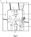
- Fig. 2 shows the press 6 of the Fig. 1 in a side view with the lower punch 7 and the upper punch 8.
- the lower punch 7 is disposed below the countertop 3 and connected to the machine frame 2.
- the upper punch 8 is arranged above the worktop 3 and also connected to the machine frame 2.
- the lower punch 7 and the upper punch 8 are pressed against each other in a pressing direction 21 in order to compact the green compact.
- the lower punch 7 is motor-adjustable with a height adjustment device 22 in the pressing direction 21 and engages on the underside of the die 4 in the build-up chambers 9A, 9B.
- the upper punch 8 is motor-adjustable with a height adjustment device 23 in the pressing direction 21 and acts on the top of the die 4 on the green body.
- press zone 24 the area between the lower punch 7 and the upper punch 8 is designated.
- the powdered or granular material 14, 15 is filled in a first process section with the filling shoe 5 in layers in the building chambers 9A, 9B, the cutting particles are set in a second process section with a set unit 25 in the material layer and in a third process section, the compression takes place of the green compact with the press 6.
- the non-active processing units must be removed from the processing zone of the respective active processing unit.
- the filling shoe 5 is moved after the filling in a position outside the press zone 24 is located. Due to the high pressing forces that the upper punch 8 has to apply during compaction, the upper punch 8 are solid and the pressing zone 24 is correspondingly large.
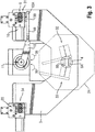
- Fig. 3 shows the filling shoe 5 in a view from above of the countertop 3, wherein the upper punch 8 of the press 6 is not shown.
- the filling shoe 5 is arranged in a position which lies outside the pressing zone 24 and is referred to as the first parking position 31 .
- the filling shoe 5 In the first parking position 31, the filling shoe 5 is connected to the first filling station 16 and the filling containers 13A, 13B of the filling shoe 5 can be filled with the first and second material 14, 15.
- the filling shoe 5 For filling the build-up chambers 9A, 9B with the materials 14, 15, the filling shoe 5 is moved from the first parking position 31 into a first end position 32 . In the first end position 32, the filling containers 13A, 13B of the filling shoe 5 are opened and the filling process begins. The filling shoe 5 is moved up to a second end position 33 via the build-up chambers 9A, 9B, which are filled with the materials 14, 15 via the filling containers 13A, 13B. In the second end position 33, the filling containers 13A, 13B of the filling shoe 5 are closed and the filling process is completed. The filling shoe 5 is moved from the second end position 33 into a second parking position 34 . The second parking position 34 is like the first parking position 31 outside the press zone 24. The various positions 31-34 of the filling shoe 5 are preset in a control device or are detected by a sensor device.
- the movement of the filling shoe 5 between the first and second parking positions 31, 34 is subdivided into a positioning movement and a filling movement.
- a positioning movement movements are referred to, which are required for positioning of the filling shoe 5 before and after filling the build-up chambers 9A, 9B.
- a setting movement and return movement are distinguished.
- the filling shoe 5 is moved from a parking position into an end position in which the filling process begins.
- the return movement of the filling shoe 5 is moved from an end position in which the filling ends in a parking position.
- the structure of the green body by layered application and compression takes place according to the following inventive method for producing a green compact from a powder or granular material.
- the process consists of several sections that are repeated iteratively until the green compact has reached the desired height.
- a first material layer is built up.
- the first section consists of several sub-steps:
- the lower punch 7 is using the height adjustment 22 lowered by the desired layer thickness of the first material layer. If there are already material layers in the build-up chambers 9A, 9B, the lower and upper punches 7, 8 are lowered together by the desired layer thickness and the upper punch 8 is then moved back to its original position.
- the filling shoe 5 is moved in a first movement direction 35 with an adjusting movement from the first parking position 31 into the first end position 32. Subsequently, the filling shoe 5 is moved to the second end position 33 via the receiving chambers 9A, 9B, which are filled with the materials 14, 15 during the filling process.
- the filling shoe 5 is moved with a return movement in the first movement direction 35 from the second end position 33 into the second parking position 34.
- the setting unit 25 sets the cutting particles in the desired distribution in the first material layer. The setting step is carried out when the cutting particles are not mixed in the material, but are placed individually in the material layer.
- the materials are compacted in a second section.
- the upper punch 8 is first lowered to the upper edge of the build-up chambers 9A, 9B. Subsequently, the lower punch 7 and the upper punch 8 are pressed against each other in the pressing direction 21 in order to compact the first material layer. After compaction, the lower punch 7 and the upper punch 8 are lowered together in a lifting movement by the desired layer thickness of the second material layer. Finally, the upper punch 8 is moved back to its original position.
- a second material layer is built up.
- the third section consists of several sub-steps:
- the filling shoe 5 is moved in a second movement direction 36 with a positioning movement from the second parking position 34 into the second end position 33.
- the filling shoe 5 is moved between the second end position 33 and the first end position 32 via the build-up chambers 9A, 9B, which are filled with the materials 14, 15 during the filling process.
- the filling shoe 5 is moved with a return movement in the second movement direction 36 from the first end position 32 into the first parking position 31.
- the setting unit 25 sets the cutting particles in the desired distribution in the second material layer.
- the second material layer is compacted by means of the adjustable lower and upper punches 7, 8 analogously to the compression of the first material layer.
- the filling movement and the positioning movements of the filling shoe 5 take place in the construction of the second material layer in the second direction of movement 36, which is directed counter to the first direction of movement 35 in the construction of the first material layer.
- the advancing movement of the filling shoe 5 is formed during the filling process in the end region of the material layer a compression zone with increased material density.
- the feed rate of the filling shoe 5 is constant during the filling movement between the end positions 32, 33 in order to set a uniform material application.
- the filling behavior of the materials 14, 15 defines the maximum possible feed rate during the filling movement. At higher feed rates during the filling movement there is a risk that the build-up chambers 9A, 9B are not filled evenly and, above all, not with the necessary amount of material.
- the maximum possible feed speed of the filling shoe is determined by the capacity of the adjusting device 11.
Landscapes
- Engineering & Computer Science (AREA)
- Mechanical Engineering (AREA)
- Manufacturing & Machinery (AREA)
- Chemical & Material Sciences (AREA)
- Ceramic Engineering (AREA)
- Inorganic Chemistry (AREA)
- Materials Engineering (AREA)
- Structural Engineering (AREA)
- Organic Chemistry (AREA)
- Powder Metallurgy (AREA)
- Footwear And Its Accessory, Manufacturing Method And Apparatuses (AREA)
Applications Claiming Priority (1)
| Application Number | Priority Date | Filing Date | Title |
|---|---|---|---|
| DE102011007728A DE102011007728A1 (de) | 2011-04-20 | 2011-04-20 | Vorrichtung und Verfahren zum Herstellen eines Grünlings aus einem pulver- oder granulatförmigen Werkstoff |
Publications (2)
| Publication Number | Publication Date |
|---|---|
| EP2514541A2 true EP2514541A2 (fr) | 2012-10-24 |
| EP2514541A3 EP2514541A3 (fr) | 2013-11-20 |
Family
ID=45607005
Family Applications (1)
| Application Number | Title | Priority Date | Filing Date |
|---|---|---|---|
| EP12154456.3A Withdrawn EP2514541A3 (fr) | 2011-04-20 | 2012-02-08 | Dispositif et procédé de fabrication d'un compact vert à partir d'une matière active sous forme de poudre ou de granulés |
Country Status (5)
| Country | Link |
|---|---|
| US (2) | US9399255B2 (fr) |
| EP (1) | EP2514541A3 (fr) |
| KR (1) | KR101956919B1 (fr) |
| CN (1) | CN102744904B (fr) |
| DE (1) | DE102011007728A1 (fr) |
Cited By (1)
| Publication number | Priority date | Publication date | Assignee | Title |
|---|---|---|---|---|
| CN118417560A (zh) * | 2024-07-01 | 2024-08-02 | 常州市知宇粉末冶金有限公司 | 含油轴承内孔冲孔设备 |
Families Citing this family (4)
| Publication number | Priority date | Publication date | Assignee | Title |
|---|---|---|---|---|
| DE102019104041A1 (de) * | 2019-02-18 | 2020-08-20 | Dorst Technologies Gmbh & Co. Kg | Verfahren zum Pulverpressen |
| KR102377546B1 (ko) * | 2020-05-29 | 2022-03-21 | 백승욱 | 세라믹 분말의 균일 충전을 위한 프레스 장치 및 이를 이용한 세라믹 제조 방법 |
| DE102020127990A1 (de) | 2020-10-23 | 2022-04-28 | Syntegon Technology Gmbh | Fülleinheit für eine Rundlaufpresse und ein Verfahren zur Bereitstellung einer optimierten Rundlaufpresse |
| DE102020127992B3 (de) * | 2020-10-23 | 2022-03-10 | Syntegon Technology Gmbh | Fülleinheit für eine Rundlaufpresse und ein Verfahren zur Bereitstellung einer optimierten Rundlaufpresse |
Family Cites Families (15)
| Publication number | Priority date | Publication date | Assignee | Title |
|---|---|---|---|---|
| US2800684A (en) * | 1953-07-28 | 1957-07-30 | Ncr Co | Apparatus for forming powdered metal parts |
| SE339082B (fr) * | 1968-10-02 | 1971-09-27 | Mannesmann Meer Ag | |
| US3752003A (en) * | 1970-12-04 | 1973-08-14 | Federal Mogul Corp | Composite heavy-duty machine element and method of making the same |
| IT999894B (it) * | 1973-12-05 | 1976-03-10 | Olivetti & Co Spa | Dispositivo per la lubrificazione delle matrici per la compattazione di materiali in polvere per pezzi sinterizzati |
| US4354811A (en) * | 1980-07-22 | 1982-10-19 | Westinghouse Electric Corp. | Workpiece pellet length control apparatus |
| US4559004A (en) * | 1984-08-24 | 1985-12-17 | Societe Anonyme De Recherche Et D'etudes Techniques | Apparatus for manufacturing bricks of compressed earth |
| IT1245757B (it) * | 1991-01-15 | 1994-10-14 | Mg 2 Spa | Macchina per il dosaggio di prodotti farmaceutici in polvere. |
| JPH0631491A (ja) * | 1992-07-17 | 1994-02-08 | Fanuc Ltd | 粉末成形機 |
| DE19903417B4 (de) * | 1999-01-29 | 2007-03-29 | Wilhelm Fette Gmbh | Verfahren zum Befüllen einer Hydraulikpresse mit Pulvern |
| DE19928245B4 (de) * | 1999-06-21 | 2006-02-09 | Eos Gmbh Electro Optical Systems | Einrichtung zum Zuführen von Pulver für eine Lasersintereinrichtung |
| DE10209746B4 (de) * | 2002-03-06 | 2004-04-15 | Dorst Maschinen- Und Anlagenbau Gmbh & Co. | Pulverbefüllungsvorrichtung, insbesondere für pulvermetallurgische Pulver, Füllschuh für eine solche Pulverbefüllungsvorrichtung und Verfahren zum Befüllen einer Matrizenöffnung mit Pulver |
| JP2005249032A (ja) * | 2004-03-03 | 2005-09-15 | Nisshinbo Ind Inc | 粉状体の擦切方法及び擦切装置 |
| FR2892051B1 (fr) * | 2005-10-19 | 2009-05-01 | Cogema | Distributeur de poudre notamment pour pastilleuse et procede de fabrication de pastilles de combustible nucleaire |
| EP2098317A1 (fr) * | 2007-12-04 | 2009-09-09 | Osterwalder AG | Procédé et dispositif de fabrication d'une pièce moulée en poudre de métal |
| DE102011118209A1 (de) * | 2011-11-12 | 2013-05-16 | Dorst Technologies Gmbh & Co. Kg | Keramik- und/oder Metallpulverpresse mit einem Füllschuh und Füllleitungen und Verfahren zum Pressen eines Presskörpers in einer solchen Presse |
-
2011
- 2011-04-20 DE DE102011007728A patent/DE102011007728A1/de not_active Ceased
-
2012
- 2012-02-08 EP EP12154456.3A patent/EP2514541A3/fr not_active Withdrawn
- 2012-02-09 KR KR1020120013126A patent/KR101956919B1/ko active Active
- 2012-04-16 CN CN201210110549.7A patent/CN102744904B/zh active Active
- 2012-04-19 US US13/451,259 patent/US9399255B2/en active Active
-
2016
- 2016-06-23 US US15/190,565 patent/US20160303655A1/en not_active Abandoned
Non-Patent Citations (1)
| Title |
|---|
| None |
Cited By (1)
| Publication number | Priority date | Publication date | Assignee | Title |
|---|---|---|---|---|
| CN118417560A (zh) * | 2024-07-01 | 2024-08-02 | 常州市知宇粉末冶金有限公司 | 含油轴承内孔冲孔设备 |
Also Published As
| Publication number | Publication date |
|---|---|
| US20160303655A1 (en) | 2016-10-20 |
| US9399255B2 (en) | 2016-07-26 |
| KR20120119990A (ko) | 2012-11-01 |
| CN102744904B (zh) | 2016-08-31 |
| CN102744904A (zh) | 2012-10-24 |
| EP2514541A3 (fr) | 2013-11-20 |
| US20120267829A1 (en) | 2012-10-25 |
| KR101956919B1 (ko) | 2019-03-11 |
| DE102011007728A1 (de) | 2012-10-25 |
Similar Documents
| Publication | Publication Date | Title |
|---|---|---|
| EP3275654B1 (fr) | Unité de revêtement, procédé de revêtement, dispositif et procédé et dispositif de fabrication additive d'un objet tridimensionnel | |
| DE102016211949A1 (de) | Beschichtungseinheit, Beschichtungsverfahren, Vorrichtung und Verfahren zum generativen Herstellen eines dreidimensionalen Objekts | |
| DE102010040261A1 (de) | Verfahren zum Herstellen eines dreidimensionalen Objekts mit einer internen Struktur | |
| WO2008049384A1 (fr) | Dispositif de production d'un objet tridimensionnel | |
| EP3200984A1 (fr) | Procédé, dispositif et module de revêtement pour la réalisation d'un objet tridimensionnel | |
| EP2514541A2 (fr) | Dispositif et procédé de fabrication d'un compact vert à partir d'une matière active sous forme de poudre ou de granulés | |
| DE102006041320A1 (de) | Beschichtereinrichtung für eine Bauvorrichtung zur Erstellung von Formteilen aus pulverartigem Baumaterial unter Einbringung von Strahlungsenergie | |
| DE102017200825A1 (de) | Anlage und Verfahren zur additiven Fertigung wenigstens eines Bauteils | |
| DE102016121648A1 (de) | Vorrichtung zur additiven Herstellung dreidimensionaler Objekte | |
| DE102005030312B4 (de) | Rundläufer-Tablettiermaschine und Verfahren zur Herstellung einer Mehrschichttablette | |
| EP3718719B1 (fr) | Installation de fabrication de plaques pourvue d'un dispositif de dosage réglable en hauteur | |
| EP2440386B1 (fr) | Dispositif et procédé de chargement d'une couche de matériau sur une plate-forme de construction ou sur au moins une couche de matériau se trouvant sur la plate-forme de construction pour la fabrication d'un objet au moyen d'un procédé de fabrication génératif | |
| DE102010038324B4 (de) | Vorrichtung zum Positionieren von Schneidpartikeln | |
| DE60020700T2 (de) | Verfahren und vorrichtung zum herstellen von schleifscheiben und solch hergestellte schleifscheibe | |
| DE19903417B4 (de) | Verfahren zum Befüllen einer Hydraulikpresse mit Pulvern | |
| WO2021078316A1 (fr) | Système et procédé de génération d'une couche d'un matériau de construction particulaire dans une imprimante 3d | |
| DE2420726A1 (de) | Verfahren zur herstellung von presskoerpern mit schichtweise verschiedener zusammensetzung fuer hochbelastbare elektrische kontakte | |
| DE10262091B4 (de) | Tablettierpresse | |
| EP2776237B1 (fr) | Procédé et presse de compression d'une pièce constituée d'au moins deux matériaux métalliques et/ou céramiques pulvérulents et/ou granulaires différents | |
| EP4584037A1 (fr) | Procédé et dispositif de production de micro-éléments et de micro-composants par fabrication additive par micro-fusion laser | |
| EP3661674A1 (fr) | Procédé pour la fabrication d'un segment opératoire pour un outil d'usinage abrasif | |
| WO2019011532A1 (fr) | Procédé d'impression 3d et dispositif d'impression 3d | |
| WO1990009874A1 (fr) | Procede et dispositif pour fabriquer un profile fait essentiellement de matieres ceramiques | |
| DE102004046147A1 (de) | Verfahren zum Herstellen von Betonsteinen | |
| WO2016113107A1 (fr) | Mode de construction à plaques de construction empilées et procédure associée à une installation de fabrication additive |
Legal Events
| Date | Code | Title | Description |
|---|---|---|---|
| PUAI | Public reference made under article 153(3) epc to a published international application that has entered the european phase |
Free format text: ORIGINAL CODE: 0009012 |
|
| AK | Designated contracting states |
Kind code of ref document: A2 Designated state(s): AL AT BE BG CH CY CZ DE DK EE ES FI FR GB GR HR HU IE IS IT LI LT LU LV MC MK MT NL NO PL PT RO RS SE SI SK SM TR |
|
| AX | Request for extension of the european patent |
Extension state: BA ME |
|
| PUAL | Search report despatched |
Free format text: ORIGINAL CODE: 0009013 |
|
| AK | Designated contracting states |
Kind code of ref document: A3 Designated state(s): AL AT BE BG CH CY CZ DE DK EE ES FI FR GB GR HR HU IE IS IT LI LT LU LV MC MK MT NL NO PL PT RO RS SE SI SK SM TR |
|
| AX | Request for extension of the european patent |
Extension state: BA ME |
|
| RIC1 | Information provided on ipc code assigned before grant |
Ipc: B22F 3/00 20060101AFI20131015BHEP Ipc: B22F 3/03 20060101ALI20131015BHEP |
|
| 17P | Request for examination filed |
Effective date: 20140520 |
|
| RBV | Designated contracting states (corrected) |
Designated state(s): AL AT BE BG CH CY CZ DE DK EE ES FI FR GB GR HR HU IE IS IT LI LT LU LV MC MK MT NL NO PL PT RO RS SE SI SK SM TR |
|
| 17Q | First examination report despatched |
Effective date: 20161111 |
|
| STAA | Information on the status of an ep patent application or granted ep patent |
Free format text: STATUS: THE APPLICATION IS DEEMED TO BE WITHDRAWN |
|
| 18D | Application deemed to be withdrawn |
Effective date: 20170523 |