EP2514680B1 - Boîte de refroidissement - Google Patents
Boîte de refroidissement Download PDFInfo
- Publication number
- EP2514680B1 EP2514680B1 EP11162765.9A EP11162765A EP2514680B1 EP 2514680 B1 EP2514680 B1 EP 2514680B1 EP 11162765 A EP11162765 A EP 11162765A EP 2514680 B1 EP2514680 B1 EP 2514680B1
- Authority
- EP
- European Patent Office
- Prior art keywords
- insulation
- insulation elements
- cooling container
- protective layer
- elements
- Prior art date
- Legal status (The legal status is an assumption and is not a legal conclusion. Google has not performed a legal analysis and makes no representation as to the accuracy of the status listed.)
- Not-in-force
Links
- 238000009413 insulation Methods 0.000 claims description 98
- 238000001816 cooling Methods 0.000 claims description 55
- 239000000463 material Substances 0.000 claims description 35
- 239000011241 protective layer Substances 0.000 claims description 30
- 239000010410 layer Substances 0.000 claims description 26
- 238000000034 method Methods 0.000 claims description 19
- 210000001503 joint Anatomy 0.000 claims description 16
- 238000007789 sealing Methods 0.000 claims description 15
- 230000000694 effects Effects 0.000 claims description 9
- 239000012774 insulation material Substances 0.000 claims description 7
- 230000007246 mechanism Effects 0.000 claims description 6
- 244000025254 Cannabis sativa Species 0.000 claims description 5
- 235000012766 Cannabis sativa ssp. sativa var. sativa Nutrition 0.000 claims description 5
- 235000012765 Cannabis sativa ssp. sativa var. spontanea Nutrition 0.000 claims description 5
- 235000009120 camo Nutrition 0.000 claims description 5
- 235000005607 chanvre indien Nutrition 0.000 claims description 5
- 239000011487 hemp Substances 0.000 claims description 5
- 210000002268 wool Anatomy 0.000 claims description 3
- 239000007787 solid Substances 0.000 claims description 2
- 239000011257 shell material Substances 0.000 description 30
- 230000001681 protective effect Effects 0.000 description 13
- 238000002955 isolation Methods 0.000 description 10
- 239000011111 cardboard Substances 0.000 description 9
- 239000002826 coolant Substances 0.000 description 8
- 239000000835 fiber Substances 0.000 description 6
- 239000011810 insulating material Substances 0.000 description 5
- 238000005259 measurement Methods 0.000 description 5
- 229940079593 drug Drugs 0.000 description 4
- 239000003814 drug Substances 0.000 description 4
- 235000013305 food Nutrition 0.000 description 4
- 230000006870 function Effects 0.000 description 4
- 238000004519 manufacturing process Methods 0.000 description 4
- 238000003860 storage Methods 0.000 description 4
- 238000010276 construction Methods 0.000 description 3
- CURLTUGMZLYLDI-UHFFFAOYSA-N Carbon dioxide Chemical compound O=C=O CURLTUGMZLYLDI-UHFFFAOYSA-N 0.000 description 2
- 229920006328 Styrofoam Polymers 0.000 description 2
- 230000008901 benefit Effects 0.000 description 2
- 235000011089 carbon dioxide Nutrition 0.000 description 2
- 238000010586 diagram Methods 0.000 description 2
- 230000002349 favourable effect Effects 0.000 description 2
- 239000002657 fibrous material Substances 0.000 description 2
- 239000011888 foil Substances 0.000 description 2
- 239000007788 liquid Substances 0.000 description 2
- 238000004806 packaging method and process Methods 0.000 description 2
- 239000004033 plastic Substances 0.000 description 2
- 229920003023 plastic Polymers 0.000 description 2
- 239000002985 plastic film Substances 0.000 description 2
- 229920006255 plastic film Polymers 0.000 description 2
- 102000004169 proteins and genes Human genes 0.000 description 2
- 108090000623 proteins and genes Proteins 0.000 description 2
- 239000008261 styrofoam Substances 0.000 description 2
- 244000198134 Agave sisalana Species 0.000 description 1
- 235000004431 Linum usitatissimum Nutrition 0.000 description 1
- 240000006240 Linum usitatissimum Species 0.000 description 1
- 229920005830 Polyurethane Foam Polymers 0.000 description 1
- 244000274883 Urtica dioica Species 0.000 description 1
- 235000009108 Urtica dioica Nutrition 0.000 description 1
- 238000010521 absorption reaction Methods 0.000 description 1
- 230000004308 accommodation Effects 0.000 description 1
- 230000006978 adaptation Effects 0.000 description 1
- 238000004026 adhesive bonding Methods 0.000 description 1
- 239000002390 adhesive tape Substances 0.000 description 1
- 230000009286 beneficial effect Effects 0.000 description 1
- 239000001913 cellulose Substances 0.000 description 1
- 229920002678 cellulose Polymers 0.000 description 1
- 230000008859 change Effects 0.000 description 1
- 238000005253 cladding Methods 0.000 description 1
- 239000011247 coating layer Substances 0.000 description 1
- 238000013461 design Methods 0.000 description 1
- 238000011161 development Methods 0.000 description 1
- 239000000945 filler Substances 0.000 description 1
- 238000011049 filling Methods 0.000 description 1
- 239000006260 foam Substances 0.000 description 1
- 239000011491 glass wool Substances 0.000 description 1
- 230000005484 gravity Effects 0.000 description 1
- 238000003780 insertion Methods 0.000 description 1
- 230000037431 insertion Effects 0.000 description 1
- 239000002655 kraft paper Substances 0.000 description 1
- 238000011068 loading method Methods 0.000 description 1
- 239000011490 mineral wool Substances 0.000 description 1
- 239000000203 mixture Substances 0.000 description 1
- 210000000056 organ Anatomy 0.000 description 1
- 239000000123 paper Substances 0.000 description 1
- 239000011496 polyurethane foam Substances 0.000 description 1
- 238000002360 preparation method Methods 0.000 description 1
- 230000008569 process Effects 0.000 description 1
- 238000004064 recycling Methods 0.000 description 1
- 239000003507 refrigerant Substances 0.000 description 1
- 230000035939 shock Effects 0.000 description 1
- 230000003313 weakening effect Effects 0.000 description 1
Images




Classifications
-
- B—PERFORMING OPERATIONS; TRANSPORTING
- B65—CONVEYING; PACKING; STORING; HANDLING THIN OR FILAMENTARY MATERIAL
- B65D—CONTAINERS FOR STORAGE OR TRANSPORT OF ARTICLES OR MATERIALS, e.g. BAGS, BARRELS, BOTTLES, BOXES, CANS, CARTONS, CRATES, DRUMS, JARS, TANKS, HOPPERS, FORWARDING CONTAINERS; ACCESSORIES, CLOSURES, OR FITTINGS THEREFOR; PACKAGING ELEMENTS; PACKAGES
- B65D81/00—Containers, packaging elements, or packages, for contents presenting particular transport or storage problems, or adapted to be used for non-packaging purposes after removal of contents
- B65D81/38—Containers, packaging elements, or packages, for contents presenting particular transport or storage problems, or adapted to be used for non-packaging purposes after removal of contents with thermal insulation
- B65D81/3825—Containers, packaging elements, or packages, for contents presenting particular transport or storage problems, or adapted to be used for non-packaging purposes after removal of contents with thermal insulation rigid container being in the form of a box, tray or like container with one or more containers located inside the external container
- B65D81/3834—Containers, packaging elements, or packages, for contents presenting particular transport or storage problems, or adapted to be used for non-packaging purposes after removal of contents with thermal insulation rigid container being in the form of a box, tray or like container with one or more containers located inside the external container the external tray being formed of different materials, e.g. laminated or foam filling between walls
-
- B—PERFORMING OPERATIONS; TRANSPORTING
- B65—CONVEYING; PACKING; STORING; HANDLING THIN OR FILAMENTARY MATERIAL
- B65D—CONTAINERS FOR STORAGE OR TRANSPORT OF ARTICLES OR MATERIALS, e.g. BAGS, BARRELS, BOTTLES, BOXES, CANS, CARTONS, CRATES, DRUMS, JARS, TANKS, HOPPERS, FORWARDING CONTAINERS; ACCESSORIES, CLOSURES, OR FITTINGS THEREFOR; PACKAGING ELEMENTS; PACKAGES
- B65D81/00—Containers, packaging elements, or packages, for contents presenting particular transport or storage problems, or adapted to be used for non-packaging purposes after removal of contents
- B65D81/38—Containers, packaging elements, or packages, for contents presenting particular transport or storage problems, or adapted to be used for non-packaging purposes after removal of contents with thermal insulation
- B65D81/3848—Containers, packaging elements, or packages, for contents presenting particular transport or storage problems, or adapted to be used for non-packaging purposes after removal of contents with thermal insulation semi-rigid container folded up from one or more blanks
- B65D81/3858—Containers, packaging elements, or packages, for contents presenting particular transport or storage problems, or adapted to be used for non-packaging purposes after removal of contents with thermal insulation semi-rigid container folded up from one or more blanks formed of different materials, e.g. laminated or foam filling between walls
-
- B—PERFORMING OPERATIONS; TRANSPORTING
- B65—CONVEYING; PACKING; STORING; HANDLING THIN OR FILAMENTARY MATERIAL
- B65D—CONTAINERS FOR STORAGE OR TRANSPORT OF ARTICLES OR MATERIALS, e.g. BAGS, BARRELS, BOTTLES, BOXES, CANS, CARTONS, CRATES, DRUMS, JARS, TANKS, HOPPERS, FORWARDING CONTAINERS; ACCESSORIES, CLOSURES, OR FITTINGS THEREFOR; PACKAGING ELEMENTS; PACKAGES
- B65D81/00—Containers, packaging elements, or packages, for contents presenting particular transport or storage problems, or adapted to be used for non-packaging purposes after removal of contents
- B65D81/38—Containers, packaging elements, or packages, for contents presenting particular transport or storage problems, or adapted to be used for non-packaging purposes after removal of contents with thermal insulation
- B65D81/3848—Containers, packaging elements, or packages, for contents presenting particular transport or storage problems, or adapted to be used for non-packaging purposes after removal of contents with thermal insulation semi-rigid container folded up from one or more blanks
- B65D81/3862—Containers, packaging elements, or packages, for contents presenting particular transport or storage problems, or adapted to be used for non-packaging purposes after removal of contents with thermal insulation semi-rigid container folded up from one or more blanks with a foam formed container located inside a folded box
Definitions
- the present invention relates to a refrigerated container and a method for its use.
- Refrigerated containers e.g. in the form of coolers, can generally be used for transport to be cooled, in some cases, other sensitive goods. In particular, they are used for the transport of food and medicines.
- the present invention further relates to a method for transporting a chilled goods and a kit for a refrigerated container.
- a thermally sensitive material should be surrounded by several insulating layers. The estate itself is surrounded directly by cooling elements, which consist of three foil cushions each. These foil cushions engage each other so that they form a first complete envelope of the product to be transported.
- This innermost enclosure is surrounded by an inner box, which is made of rigid polyurethane foam panels.
- the inner box is enclosed by a further coating layer.
- This cladding layer consists of four side plates, a bottom plate and a ceiling plate. These plates should be made of foam.
- As a further outer layer is an outer packaging substantially in the Form of a common box provided.
- the published patent application 26 52 354 discloses a cryogenic storage tank.
- This storage tank should consist of an inner vessel for receiving a good and this enclosing gas-tight outer container.
- the space between the inner vessel and the outer container can be evacuated.
- fiber layer layers can be additionally provided.
- This concept allows the use of a variety of different fiber layers.
- the isolation effect is most likely generated by the evacuation of the cavity formed.
- the vessel has filled and unfilled a lot of space.
- a design in which a vacuum can be maintained for a long time usually both not quite inexpensive and shock-sensitive.
- the publication US 2009/078708 A1 discloses a container for transporting refrigerated goods, which comprises one of a plurality of panels, which are formed partly from Insolationsmaterial and partly from phase change memory material.
- the present invention seeks to improve the state of the art. It should be provided a long and reliable cooling cool box. In an important aspect, this is done with manufacturing processes that usually require low investment costs. In another important aspect, this should be achieved in an ecological way. Ecological considerations concern both the cool box itself and process aspects in its manufacture and use.
- the present invention relates to a refrigerated container, which can be provided for example in a form which is commonly referred to as a cool box.
- the cooling container has a receiving space. This can be, for example, cuboid or cylindrical.
- a specially adapted form of the recording room into consideration.
- additional support and cushioning means may be provided in the receiving space.
- parts of the insulation material described in more detail herein, in particular an insulation layer can be designed in such a way that they can assume supporting and cushioning functions for certain products.
- the container is also suitable for receiving warm or hot materials (including food) and can then serve to keep warm. This is to be understood.
- the cooling container is surrounded by an outer shell.
- This can give the cooling container any conventional form. For example, a cylindrical shape or a cuboid shape is well in question.
- the outer shell should be made of a solid self-supporting material.
- the geometric stability of the cool box can be given essentially by the material of the outer shell of the box.
- the outer shell should already offer a certain insulating effect. For this purpose it should have air pockets or air chambers.
- the outer shell come as materials in principle plastics, Styrofoam and cardboard materials, such as kraft cardboard or corrugated board, in question.
- Air pockets or air chambers serve a preferred relationship between stability and air Isolation effect to achieve. Therefore, corrugated board is particularly well considered.
- the material comprises 10 to 90 volume percent air chambers, suitably 20 to 80 volume percent or even 50 to 70 volume percent.
- a double-sided laminated corrugated board Conveniently, a double-sided laminated corrugated board.
- the easy printability of the outer surface of the outer shell is a relevant additional benefit of such material.
- a suitable Wellpapp material is the so-called B-wave, which zwichen two outer layers has a wave position with wave pitch between 5.5 and 6.5 mm and wave height between 2.2 and 3.0 mm.
- such materials for example among the plastic materials, which generally have less volume percent of air chambers or even no air chambers would be suitable for use as an outer shell.
- the cooling container should have an insulation layer which is formed from a plurality of individual insulation elements.
- the insulation elements contain a fibrous insulating material having a density of less than 100 Kg / m 3 , expediently, the insulation elements consist mainly or substantially of the fibrous insulating material. Even lower densities of the fibrous insulating material may be advantageous, for example, densities in the range of 10 to 50 or 20 to 40 Kg / m 3 . These density specifications relate to the insulation material, so for example a fibrous wool.
- the density of the respective fibers themselves may be higher, for example fibers with a density of 100-200 kg / m 3 are useful.
- Suitable materials for producing a corresponding insulation layer are hemp, sisal, nettle or flax.
- glass wool, rock wool or cellulose come into consideration.
- the corresponding fibers can be used to produce insulation wool. Particularly advantageous, however, are fibrous Materials that contain no proteins. These have proven not only beneficial for the isolation, but also avoid hygiene
- the insulation layer is to be formed from a plurality of individual insulation elements.
- the insulation elements may be substantially flat.
- the insulation elements can thus have the shape of a cuboid whose thickness is only one fifth, one tenth or one twentieth of the mean of the side lengths. In this way, insulation elements can be made available which are easy to produce but also easy to store. In particular, they are easily stackable.
- the insulation elements can be used with sufficient standardization with cooling containers of different sizes.
- the cooling container further has a protective layer, which is arranged between the receiving space and the insulating layer.
- a protective layer leads to additional thermal insulation.
- the protective layer can meet the corresponding hygienic requirements.
- the protective layer can be optimized for the requirements of such transport.
- the cooling container is constructed so that a refrigerated goods is only in contact with the protective layer. If, for example, it is necessary to comply with stringent drug legislation requirements (organ transport requirements may also be considered here), it is sufficient to optimize the protective layer for these transport tasks.
- the protective layer can be provided, for example, essentially by a plastic film.
- the insulation elements can form-fit surround the receiving space. In this case, it comes into question that the insulation elements abut each other in the interior of the outer shell accurately to abutting joints.
- the insulation elements carry the protective layer. It is contemplated that the individual insulation elements are completely or at least partially covered by the protective layer.
- the protective layer can enclose the insulation elements like an envelope.
- the protective layer can also enclose the insulation elements in the form of tube sections (so-called flowpacks).
- connection strip is formed from the material of the protective layer, which is arranged between two insulating elements.
- the connection strip may be an integral continuation of the protective layer surrounding the insulation elements. It is also possible to use two (or more) connection strips per insulation element. Such a connection strip is placed in the butt joint between two insulation elements. There he unfolds a sealing effect, for example, to compensate for not quite accurate abutment surfaces in the insulation elements.
- the connection strip will also be referred to herein as a sealing strip.
- the connecting strip can also be arranged outside a butt joint and cover it. Advantageously, it is placed between butt joint and outer shell. In this function, the connection strip would be referred to herein as insulation strips.
- the connection strip is thus advantageously arranged (completely or at least partially) between each two insulation elements and is in this case wholly or partly in the region of the butt joint and can also cover it to the outside.
- the protective layer is formed by a plastic film. Because of the machines that are sufficiently available for such purposes, it is expedient to attach the protective cover around the insulation elements in the form of a tubular sheath (or a "flow pack” or “flow wrap”). At both ends, the respective tube sections are sealed in the usual way.
- the insulation elements can also be enclosed by a corrugated cardboard envelope.
- the outer surfaces of the corrugated cardboard casings can then form the protective layer of the cooling container.
- a connecting strip for use as a sealing and / or insulating strip, for example by means of a protruding tab.
- a cooling container in which the outer shell has the shape of a two-part box.
- a box consists of a lower part and a lid part.
- the lower part has a bottom and surrounding side wall sections.
- the lid part has a lid and surrounding sidewall portions.
- this insulating layer will completely cover the side wall portions of the lid part.
- the insulation elements must be higher than the korrenspond Schlierenden side wall portions of the base - conveniently at least 20% to 200% or 50 to 100% higher.
- the invention also extends to a kit for a refrigerated container of the general and more specific embodiment described herein. It is expedient, in particular, a cooling container and a kit for this with a foldable lower part and a fold-lid part.
- Lower part and Lid parts can then be stored in a substantially flat configuration, in which they include no or only a small empty space compared to the receiving space (eg less than 10% of the receiving space).
- the unfolding is conceivable, for example, by a folding mechanism with joints.
- a foldable lower part and a foldable lid part can be produced particularly easily if a semi-rigid material, eg corrugated cardboard, is used as the blank material for the same.
- such a kit also includes a plurality of substantially flat insulation elements, for example four or six insulation elements. It is also useful if the insulation elements are wrapped with a film. It is also expedient if the cover part of the kit or generally in the sense of this invention, the cover part of the cooling container has a holding mechanism for holding an insulating element. Such a holding mechanism can be made available, for example, by means of fold-out, preferably resiliently slightly biased, tabs.
- the loading of the container base can also be done after the construction of the container lid part.
- the method also includes a final step of the partial or complete disassembly of the cooling container into individual parts, ie in the lower part, the cover part and insulating elements.
- such a method uses a kit of the type described herein and a cool box with the other features described herein. It is particularly advantageous if the insulation elements are reused in this method. For this purpose, it is expedient if the insulation elements and cooling containers have normalized sizes. The insulation elements can then be reused with a new outer shell. As a rule, the insulation elements are used with the protective cover surrounding them. However, it may also be considered to continue to use only the insulation material of the insulation elements, and to replace the protective cover, or to provide with a further protective cover surrounding the first protective cover. The reuse of upper and lower part may also be 840 insomniaßg in individual cases, but can also be omitted. When these parts are made of corrugated board, their delivery to conventional paper recycling is usually worth considering. For a further cooling transport, a cooling container with an unused outer shell can then be made available.
- the invention also relates to a kit system for the production of refrigerated containers of various sizes and to a corresponding method.
- a kit system can be provided or used in which material for the outer shell of cooling containers of different sizes is provided. Further Isolation elements are provided.
- the size of the outer shells and the size of the insulation elements is coordinated so that insulation elements can be used with different outer shells. For example, if two parallelepiped outer sheaths are provided, each having smaller end faces and longer side faces, a kit system can be realized in the following manner: The side face of a smaller outer sheath can be exactly the size of the face of a larger outer sheath.
- the insulation elements are used in different orientations in different outer sheaths, for example, rotated 90 degrees to each other.
- cuboid cooling containers are used, each having six insulation elements of three different sizes. Equal-sized insulation elements are used in each case on the opposite end faces, opposite side surfaces and in the lid and in the floor.
- a refrigerated container having an outer shell of different size one or even two pairs of insulation elements in another position may then also be used.
- the outer shells can be cuboid.
- three pairs of insulation elements of the same size can be provided for an outer shell further.
- the second selection may include at least one pair of isolation elements, which is also included in the first selection.
- the instructions for constructing a cooling container of first or second size may be part of the method.
- the Fig. 1 shows some basic elements of a not yet assembled cooling container 10.
- the cooling container 10 consists of an outer shell 12, in which an insulating layer 14 is provided.
- the insulation layer 14 is provided by a plurality of, here initially two individual insulation elements 16.
- the elements 16 are substantially flat, so have the shape of flat cuboid. Since the outer shell in the example shown is that of a parallelepiped-shaped cooling container, the insulation elements 16 can be comfortably inserted accurately along the inner walls of the outer shell.
- Fig. 2 shows the outer shell 12, in which two insulation elements 16A and 16B have been accurately inserted. These two elements are parts of the insulating layer 14.
- Fig. 3 shows a further step of assembling a cooling element according to the invention from various individual parts.
- the outer shell 12 is still provided in this state only by a lower part 20.
- This base has an open box shape.
- the outer shell 12 is now equipped with four visible insulation elements, which nestle against the side walls. These are the ones Isolation elements 16A, 16B, 16C and 16D. These four insulation elements abut each other flush.
- a protective layer 18 is provided on its inner surface.
- the insulation elements project beyond the lower part 20 of the outer shell 12. They enclose a receiving space 22. In the lower part 20 with the thus positioned insulation elements 16 could be given a refrigerated goods.
- Fig. 4 shows closer structural details of a suitable insulating element 16.
- This element may consist of a suitable insulating material, which is surrounded by a protective sheath 24.
- This protective sheath 24 may be provided in the approximate shape of a tubular film.
- the protective enclosure may include one, or as shown here, two end strips 26A and 26B. Conveniently, the end strips also serve to close the open ends of the protective sheath 24.
- the protective sheath thus has essentially a flat cuboid shape, but it does not have to have planar end faces, but rather may have structured end faces.
- the structure of the end faces may include, for example, the end strips 26 shown.
- Fig. 5 shows a plan view of a prepared for receiving a refrigerated goods cooling container, as shown in a perspective view in Fig. 3 was shown.
- This supervision can be seen from the circulation, which describes the shell 12, which describes the shape of a rectangle.
- isolation elements 16A, 16B, 16C and 16D are provided.
- the bottom of the refrigerating container 12 is covered with an insulating member 16E.
- These insulation elements 16 provide a protective layer in the direction of the receiving space of the cooling container.
- This is a substantially continuous protective layer, but having different sections, namely the sections 18A, 18B, 18C and 18D, which are provided by the respective insulating elements 16.
- the individual isolation elements are on all sides of the Enclosed material of the protective layer, which provide a protective sheath 24 for the insulation elements 16.
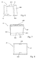
- Fig. 6 - 10 show now more details of the cover part 40. From the perspective view of Fig. 6 is first to realize that one Cover part 40 can be made useful from a blank 42. For example, it could be a blank made from a corrugated cardboard web. By a corresponding pattern, it is possible to produce a cover part with appropriate lateral wall sections. For example, the opposing wall portions 46A and 46C have a simple material thickness. On the other hand, in the wall portion 46B, two sheets of material of the blank are superimposed.
- Fig. 7 shows how the actual cover 44 of the cover part 40 can be covered with an insulating element.
- the insulating member 16F completely covers the lid surface 44. So that it does not fall out of the cover under the influence of gravity, in particular when placing the cover part 40 on the lower part 20, the insulating element 16F is held by a holding mechanism.
- This holding mechanism may for example consist of retaining tabs 48A and 48B. Such retaining tabs may be integrally provided in the blank 42. They can be resiliently biased.
- Fig. 8 shows the lid part, in which the insulating element 16F has been used accurately.
- the insulating member 16F is now obtained from the opposing retaining tabs 48A and 48B.
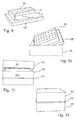
- Fig. 9 shows an alternative inner part for the lid.
- An insulating element 16F of the known type is in this case combined with a coolant intake.
- the coolant intake can be made of corrugated cardboard, for example. Corrugated board has the necessary rigidity to make a cuboid comfortably.
- the insulation element 16F may be expediently surrounded by a corrugated cardboard sleeve. But it can also be surrounded by a protective sheath in the form of a film. Between film and coolant absorption can be made for example by gluing a convenient connection.
- the coolant intake can be dry ice or pick up another suitable coolant. Provide circulation holes, it is expedient.
- Fig. 10 the insertion of such an insulating member 16F is shown with coolant receptacle 50 in a cover part 40.
- a coolant intake is not always necessary in the context of the present invention. It may be expedient to bring a coolant, such as dry ice, into direct contact with the item to be cooled.
- a cover member 40 is shown in perspective on a lower part 20.
- the insulating layer is already formally liquid, the lower part 20 is introduced and projects beyond the upper edge of the lower part.
- the insulating layer 14 can also serve as an insulating layer in the region of the wall sections 46 of the cover part. It is by the lower part 20 superior insulation layer 14 very easy to pass the cover fit, so that a seamless outer shell is formed.
- the transportable cool box is in Fig. 12 shown.
- Lower part 20 and cover part 40 form a smooth, uniform outer shell 12.
- This butt joint can be covered by a connecting band.
- This connecting band ensures both an even better insulation and the mechanical connection of lower part 20 and cover part 40.
- a commercially available adhesive tape is generally suitable as a connecting band.
- Fig. 13 now shows another aspect of the invention.
- Standardized flat insulation elements can be made using a flow wrap machine 60 (or "flow wrap machine") which is readily available for other uses in the machine market.
- a tubular bag machine 60 initially has a supply for wrapping material 62. Only the most essential elements of the machine are discussed here.
- Behind the supply of the wrapping material 62 is a folding box 64th arranged.
- folding box 64 side edges of the wrapping material 62 can be erected during operation.
- the wrapping material 62 thus moves ahead with a U-shaped cross section.
- In the upwardly open U individual internal parts 66 can be inserted for insulation elements.
- these elements may be cuboid hemp elements.
- These elements converge towards a transverse shooter 68.
- the cross-member 68 discharges portions of the filler material and simultaneously seals the ends. In this way, the insulation elements are wrapped and sealed. At the same time, the very advantageous end strips are generated by the transverse sealer 68.
- Fig. 14 shows that the cooling container 10 according to the invention is not only superior in terms of economic and ecological view known concepts, but also provides an excellent cooling effect.
- Shown is a graph representing temperature data as curve K1 and relative humidity data as curve K2.
- the diagram is based on measurements on a cooling container according to the invention, in which measurement was carried out over a period of about 45 hours. After a preparation time, the measurement is read off at an hour 0 on the abscissa. At the hour 0, a temperature of about -40 degrees Celsius is measured. Over the first 10 hours, this temperature is essentially maintained. An increase over a temperature of -30 degrees, which is still very sufficient for almost all practical purposes, does not take place until after about 23 hours.
Landscapes
- Engineering & Computer Science (AREA)
- Mechanical Engineering (AREA)
- Packages (AREA)
Claims (12)
- Récipient de refroidissement (10), lequel présente un espace de réception (22) et une gaine extérieure (12), une couche d'isolation (14) intérieure et une couche de protection (18), où la gaine extérieure (12) est constituée d'un matériau autoporteur solide, laquelle présente des chambres à air, et la couche d'isolation (14) est formée par une multitude d'éléments d'isolation (16) individuels, lesquels contiennent un matériau isolant fibreux avec une densité inférieure à 100 kg/m3, et la couche de protection (18) est disposée entre l'espace de réception (22) et la couche d'isolation (14) et chez lequel les éléments d'isolation (16) entourent un espace de réception (22) par complémentarité des formes, caractérisé en ce qu'au moins une bande de liaison (30 : 32) est formée de manière complémentaire à partir du matériau de la couche de protection (18), laquelle est placée dans le joint d'amortissement entre deux éléments d'isolation (16) et y exerce un effet d'étanchéité sous la forme d'une bande d'étanchéité.
- Récipient de refroidissement (10) selon l'une des revendications précédentes, chez lequel les éléments d'isolation (16) sont essentiellement plats.
- Récipient de refroidissement (10) selon l'une des revendications précédentes, chez lequel le matériau isolant fibreux est de la laine de chanvre.
- Récipient de refroidissement (10) selon l'une des revendications précédentes, chez lequel les éléments d'isolation (16) portent la couche de protection (18).
- Récipient de refroidissement (10) selon la revendication précédente, chez lequel les éléments d'isolation (16) sont enveloppés pratiquement totalement par le matériau de la couche de protection (18).
- Récipient de refroidissement (10) selon l'une des revendications précédentes, chez lequel la gaine extérieure (12) a la forme d'une boîte en deux parties, laquelle est constituée d'une partie inférieure (20) et d'une partie couvercle (40).
- Récipient de refroidissement (10) selon la revendication précédente, chez lequel au moins quelques éléments d'isolation (16) dépassent de l'arête supérieure de la partie inférieure (20) et forment une couche d'isolation (14) dans la partie couvercle (40).
- Kit pour un récipient de refroidissement (10), lequel est constitué d'une partie inférieure (20) pouvant se déplier et d'une partie couvercle (40) pouvant se déplier et d'une multitude d'éléments d'isolation (16) essentiellement plats (16), où les éléments d'isolation (16) portent une couche de protection, caractérisé en ce qu'au moins une bande de liaison (30 ; 32) est formée de manière complémentaire à partir du matériau de la couche de protection (18), laquelle peut être placée entre deux éléments d'isolation (16) respectifs et qu'un effet d'étanchéité peut s'y développer sous la forme d'une bande d'étanchéité.
- Kit selon l'une des revendications précédentes, chez lequel la partie couvercle (40) présente un mécanisme de fixation (30) pour le maintien d'un élément d'isolation (16) .
- Procédé pour le transport d'un produit réfrigéré, lequel comprend les étapes suivantes :- mise à disposition d'un kit,- montage de la partie inférieure (20) du récipient de refroidissement (10) en partant d'un état de livraison à l'état déplié,- équipement de la partie inférieure (20) du récipient de refroidissement (10) avec des éléments d'isolation (16), lesquels portent une couche de protection et chez lesquels au moins une bande de liaison (30 ; 32) est formée de manière complémentaire à partir du matériau de la couche de protection (16), laquelle est placée dans le joint d'étanchéité entre deux éléments d'isolation (16) respectifs et un effet d'étanchéité s'y développe sous la forme de bandes d'étanchéité,- équipement de la partie inférieure (20) du récipient de refroidissement (10) avec un produit réfrigéré,- montage de la partie couvercle (40) du récipient de refroidissement (10),- transport du produit réfrigéré,- démantèlement du récipient de refroidissement (10) en pièces individuelles.
- Procédé selon la revendication précédente, chez lequel un kit selon l'une des revendications 8 ou 9 est employé.
- Procédé selon la revendication précédente, chez lequel les éléments d'isolation (16) sont ré-employés.
Priority Applications (1)
| Application Number | Priority Date | Filing Date | Title |
|---|---|---|---|
| EP11162765.9A EP2514680B1 (fr) | 2011-04-18 | 2011-04-18 | Boîte de refroidissement |
Applications Claiming Priority (1)
| Application Number | Priority Date | Filing Date | Title |
|---|---|---|---|
| EP11162765.9A EP2514680B1 (fr) | 2011-04-18 | 2011-04-18 | Boîte de refroidissement |
Publications (2)
| Publication Number | Publication Date |
|---|---|
| EP2514680A1 EP2514680A1 (fr) | 2012-10-24 |
| EP2514680B1 true EP2514680B1 (fr) | 2016-11-09 |
Family
ID=44117513
Family Applications (1)
| Application Number | Title | Priority Date | Filing Date |
|---|---|---|---|
| EP11162765.9A Not-in-force EP2514680B1 (fr) | 2011-04-18 | 2011-04-18 | Boîte de refroidissement |
Country Status (1)
| Country | Link |
|---|---|
| EP (1) | EP2514680B1 (fr) |
Cited By (1)
| Publication number | Priority date | Publication date | Assignee | Title |
|---|---|---|---|---|
| DE102016008887A1 (de) * | 2016-07-20 | 2018-01-25 | Fraunhofer-Gesellschaft zur Förderung der angewandten Forschung e.V. | Kühlfahrzeug und Verfahren zum Transport von Kryoproben |
Families Citing this family (8)
| Publication number | Priority date | Publication date | Assignee | Title |
|---|---|---|---|---|
| DE202014008814U1 (de) | 2014-11-07 | 2016-02-11 | Va-Q-Tec Ag | Transportbehälter |
| EP3061706B1 (fr) | 2015-02-27 | 2018-04-04 | Dinkhauser Kartonagen Swiss AG | Emballage |
| DE202015006539U1 (de) | 2015-09-16 | 2015-11-17 | Hartschaumzuschnitte Ilmenau Gmbh | Volumenvariable Thermoverpackung |
| EP3144248A1 (fr) | 2015-09-21 | 2017-03-22 | Dinkhauser Kartonagen Swiss AG | Emballage |
| DE202016100510U1 (de) | 2016-02-02 | 2016-02-11 | Nordpack Gmbh | Isolierverpackung und die Isolierverpackung beinhaltende Umverpackung |
| DE102016008869A1 (de) * | 2016-07-20 | 2018-01-25 | Fraunhofer-Gesellschaft zur Förderung der angewandten Forschung e.V. | Kühlbehälter und Verfahren zum Transport von Kryoproben |
| DE202018101998U1 (de) | 2018-04-12 | 2019-07-17 | Hans Kolb Wellpappe Gmbh & Co. Kg | Klimabox |
| WO2023014721A1 (fr) * | 2021-08-03 | 2023-02-09 | Viking Packaging Uk Ltd | Emballage protégé contre les chocs pour le transport par des systèmes d'aéronefs pilotés à distance |
Family Cites Families (7)
| Publication number | Priority date | Publication date | Assignee | Title |
|---|---|---|---|---|
| US1904400A (en) * | 1931-07-24 | 1933-04-18 | Ralph L Bangs | Box |
| US5111957A (en) * | 1988-06-08 | 1992-05-12 | Transtech Service Network, Inc. | Method and apparatus for packaging refrigerated goods |
| US5201868A (en) * | 1991-01-22 | 1993-04-13 | Rock-Tenn Company | Insulated shipping container |
| DE20018635U1 (de) | 2000-10-31 | 2001-03-01 | Dade Behring Marburg GmbH, 35041 Marburg | Isolierbehälter |
| DE10206109C1 (de) | 2002-02-13 | 2003-06-26 | Ghassan Sowan | Verpackung zum Transport von thermisch empfindlichen Produkten |
| US20090078708A1 (en) * | 2007-09-20 | 2009-03-26 | Preston Noel Williams | Temperature Maintaining Package Having Corner Discontinuities |
| US8365943B2 (en) * | 2009-04-13 | 2013-02-05 | Recycool, Inc. | Cellulose based recyclable container |
-
2011
- 2011-04-18 EP EP11162765.9A patent/EP2514680B1/fr not_active Not-in-force
Non-Patent Citations (1)
| Title |
|---|
| None * |
Cited By (2)
| Publication number | Priority date | Publication date | Assignee | Title |
|---|---|---|---|---|
| DE102016008887A1 (de) * | 2016-07-20 | 2018-01-25 | Fraunhofer-Gesellschaft zur Förderung der angewandten Forschung e.V. | Kühlfahrzeug und Verfahren zum Transport von Kryoproben |
| DE102016008887A8 (de) * | 2016-07-20 | 2018-05-30 | Fraunhofer-Gesellschaft zur Förderung der angewandten Forschung e.V. | Kühlfahrzeug und Verfahren zum Transport von Kryoproben |
Also Published As
| Publication number | Publication date |
|---|---|
| EP2514680A1 (fr) | 2012-10-24 |
Similar Documents
| Publication | Publication Date | Title |
|---|---|---|
| EP2514680A1 (fr) | Boîte de refroidissement | |
| DE68915161T2 (de) | Behälter zur lagerung und verteilung von nährmitteln. | |
| DE60106637T2 (de) | Flexibler behälter mit flachen wandungen | |
| DE69506229T2 (de) | Faltbarer isolierbehälter zum transport und verpacken | |
| DE69931387T2 (de) | Aufblasbare isolierungsinnenbekleidung für versandbehälter | |
| DE69508946T2 (de) | Versandbehälter und verfahren zu seiner herstellung | |
| WO2017055280A1 (fr) | Cellule de stockage à protection thermique d'une boîte de transport frigorifique | |
| DE202017003908U1 (de) | Transportbox zum fachgerechten Transportieren einer temperierten und/oder stoßempfindlichen Ware, wie Kühlgut | |
| DE202017103230U1 (de) | Verpackungsanordnung zum Transport von temperaturempfindlicher Ware | |
| DE69912088T2 (de) | Wärmeisolierender behälter | |
| US20160347531A1 (en) | Insulated package system, insert panels therefor, and method of assembly | |
| WO2014076586A1 (fr) | Conteneur isotherme modulaire et procédé pour l'utiliser | |
| DE112021000846T5 (de) | Biologisch abbaubare Isolierstrukturen, Anordnungen und assoziierte Verfahren zur Herstellung derartiger Strukturen | |
| DE1802812A1 (de) | Isolierende Verpackung und isolierte Packung einer gefrorenen Nachtischspeise | |
| DE202015004047U1 (de) | Wärmesolierender Korpus für ein Kühlgerät sowie Kühlgerät mit einem wärmeisolierenden Korpus | |
| WO2017133801A1 (fr) | Emballage isolant et suremballage contenant ledit emballage isolant | |
| EP2085317B1 (fr) | Récipient thermique doté d'une isolation thermique de marchandises pour le transport et le stockage | |
| DE202019001700U1 (de) | Thermisch isolierende Verpackungseinheit | |
| DE10301318B4 (de) | Wärmedämmbehältnis mit Vakuumdämmplatten | |
| DE102017111720B4 (de) | Verpackung zum wärmeisolierten Transport von Waren | |
| DE102015007277A1 (de) | Wärmeisolierender Korpus für ein Kühlgerät sowie Kühlgerät mit einem wärmeisolierenden Korpus | |
| DE202019101109U1 (de) | Folienverbund und Folien-Einlagesystem | |
| DE944057C (de) | Verpackung fuer kissenfoermige, aus einem Schlauch hergestellte Beutel | |
| DE102014014390A1 (de) | Verpackung zum Transport von temperaturempfindlicher Ware, Versandsystem mit Teilen für die Verpackung sowie Verfahren zum Verpacken und Versenden von temperaturempfindlicher Ware | |
| DE2128214A1 (de) | Faltkarton |
Legal Events
| Date | Code | Title | Description |
|---|---|---|---|
| PUAI | Public reference made under article 153(3) epc to a published international application that has entered the european phase |
Free format text: ORIGINAL CODE: 0009012 |
|
| AK | Designated contracting states |
Kind code of ref document: A1 Designated state(s): AL AT BE BG CH CY CZ DE DK EE ES FI FR GB GR HR HU IE IS IT LI LT LU LV MC MK MT NL NO PL PT RO RS SE SI SK SM TR |
|
| AX | Request for extension of the european patent |
Extension state: BA ME |
|
| 17P | Request for examination filed |
Effective date: 20130424 |
|
| 17Q | First examination report despatched |
Effective date: 20130806 |
|
| GRAP | Despatch of communication of intention to grant a patent |
Free format text: ORIGINAL CODE: EPIDOSNIGR1 |
|
| INTG | Intention to grant announced |
Effective date: 20160825 |
|
| GRAS | Grant fee paid |
Free format text: ORIGINAL CODE: EPIDOSNIGR3 |
|
| GRAA | (expected) grant |
Free format text: ORIGINAL CODE: 0009210 |
|
| AK | Designated contracting states |
Kind code of ref document: B1 Designated state(s): AL AT BE BG CH CY CZ DE DK EE ES FI FR GB GR HR HU IE IS IT LI LT LU LV MC MK MT NL NO PL PT RO RS SE SI SK SM TR |
|
| REG | Reference to a national code |
Ref country code: GB Ref legal event code: FG4D Free format text: NOT ENGLISH |
|
| REG | Reference to a national code |
Ref country code: AT Ref legal event code: REF Ref document number: 843671 Country of ref document: AT Kind code of ref document: T Effective date: 20161115 Ref country code: CH Ref legal event code: EP |
|
| REG | Reference to a national code |
Ref country code: IE Ref legal event code: FG4D Free format text: LANGUAGE OF EP DOCUMENT: GERMAN |
|
| REG | Reference to a national code |
Ref country code: DE Ref legal event code: R096 Ref document number: 502011011079 Country of ref document: DE |
|
| PG25 | Lapsed in a contracting state [announced via postgrant information from national office to epo] |
Ref country code: LV Free format text: LAPSE BECAUSE OF FAILURE TO SUBMIT A TRANSLATION OF THE DESCRIPTION OR TO PAY THE FEE WITHIN THE PRESCRIBED TIME-LIMIT Effective date: 20161109 |
|
| REG | Reference to a national code |
Ref country code: LT Ref legal event code: MG4D |
|
| REG | Reference to a national code |
Ref country code: NL Ref legal event code: MP Effective date: 20161109 |
|
| REG | Reference to a national code |
Ref country code: FR Ref legal event code: PLFP Year of fee payment: 7 |
|
| PG25 | Lapsed in a contracting state [announced via postgrant information from national office to epo] |
Ref country code: NL Free format text: LAPSE BECAUSE OF FAILURE TO SUBMIT A TRANSLATION OF THE DESCRIPTION OR TO PAY THE FEE WITHIN THE PRESCRIBED TIME-LIMIT Effective date: 20161109 Ref country code: SE Free format text: LAPSE BECAUSE OF FAILURE TO SUBMIT A TRANSLATION OF THE DESCRIPTION OR TO PAY THE FEE WITHIN THE PRESCRIBED TIME-LIMIT Effective date: 20161109 Ref country code: GR Free format text: LAPSE BECAUSE OF FAILURE TO SUBMIT A TRANSLATION OF THE DESCRIPTION OR TO PAY THE FEE WITHIN THE PRESCRIBED TIME-LIMIT Effective date: 20170210 Ref country code: LT Free format text: LAPSE BECAUSE OF FAILURE TO SUBMIT A TRANSLATION OF THE DESCRIPTION OR TO PAY THE FEE WITHIN THE PRESCRIBED TIME-LIMIT Effective date: 20161109 Ref country code: NO Free format text: LAPSE BECAUSE OF FAILURE TO SUBMIT A TRANSLATION OF THE DESCRIPTION OR TO PAY THE FEE WITHIN THE PRESCRIBED TIME-LIMIT Effective date: 20170209 |
|
| PG25 | Lapsed in a contracting state [announced via postgrant information from national office to epo] |
Ref country code: ES Free format text: LAPSE BECAUSE OF FAILURE TO SUBMIT A TRANSLATION OF THE DESCRIPTION OR TO PAY THE FEE WITHIN THE PRESCRIBED TIME-LIMIT Effective date: 20161109 Ref country code: PT Free format text: LAPSE BECAUSE OF FAILURE TO SUBMIT A TRANSLATION OF THE DESCRIPTION OR TO PAY THE FEE WITHIN THE PRESCRIBED TIME-LIMIT Effective date: 20170309 Ref country code: FI Free format text: LAPSE BECAUSE OF FAILURE TO SUBMIT A TRANSLATION OF THE DESCRIPTION OR TO PAY THE FEE WITHIN THE PRESCRIBED TIME-LIMIT Effective date: 20161109 Ref country code: RS Free format text: LAPSE BECAUSE OF FAILURE TO SUBMIT A TRANSLATION OF THE DESCRIPTION OR TO PAY THE FEE WITHIN THE PRESCRIBED TIME-LIMIT Effective date: 20161109 Ref country code: PL Free format text: LAPSE BECAUSE OF FAILURE TO SUBMIT A TRANSLATION OF THE DESCRIPTION OR TO PAY THE FEE WITHIN THE PRESCRIBED TIME-LIMIT Effective date: 20161109 Ref country code: IS Free format text: LAPSE BECAUSE OF FAILURE TO SUBMIT A TRANSLATION OF THE DESCRIPTION OR TO PAY THE FEE WITHIN THE PRESCRIBED TIME-LIMIT Effective date: 20170309 Ref country code: HR Free format text: LAPSE BECAUSE OF FAILURE TO SUBMIT A TRANSLATION OF THE DESCRIPTION OR TO PAY THE FEE WITHIN THE PRESCRIBED TIME-LIMIT Effective date: 20161109 |
|
| PG25 | Lapsed in a contracting state [announced via postgrant information from national office to epo] |
Ref country code: SK Free format text: LAPSE BECAUSE OF FAILURE TO SUBMIT A TRANSLATION OF THE DESCRIPTION OR TO PAY THE FEE WITHIN THE PRESCRIBED TIME-LIMIT Effective date: 20161109 Ref country code: DK Free format text: LAPSE BECAUSE OF FAILURE TO SUBMIT A TRANSLATION OF THE DESCRIPTION OR TO PAY THE FEE WITHIN THE PRESCRIBED TIME-LIMIT Effective date: 20161109 Ref country code: CZ Free format text: LAPSE BECAUSE OF FAILURE TO SUBMIT A TRANSLATION OF THE DESCRIPTION OR TO PAY THE FEE WITHIN THE PRESCRIBED TIME-LIMIT Effective date: 20161109 Ref country code: EE Free format text: LAPSE BECAUSE OF FAILURE TO SUBMIT A TRANSLATION OF THE DESCRIPTION OR TO PAY THE FEE WITHIN THE PRESCRIBED TIME-LIMIT Effective date: 20161109 Ref country code: RO Free format text: LAPSE BECAUSE OF FAILURE TO SUBMIT A TRANSLATION OF THE DESCRIPTION OR TO PAY THE FEE WITHIN THE PRESCRIBED TIME-LIMIT Effective date: 20161109 |
|
| PGFP | Annual fee paid to national office [announced via postgrant information from national office to epo] |
Ref country code: FR Payment date: 20170425 Year of fee payment: 7 Ref country code: CH Payment date: 20170427 Year of fee payment: 7 Ref country code: GB Payment date: 20170528 Year of fee payment: 7 |
|
| REG | Reference to a national code |
Ref country code: DE Ref legal event code: R097 Ref document number: 502011011079 Country of ref document: DE |
|
| PG25 | Lapsed in a contracting state [announced via postgrant information from national office to epo] |
Ref country code: SM Free format text: LAPSE BECAUSE OF FAILURE TO SUBMIT A TRANSLATION OF THE DESCRIPTION OR TO PAY THE FEE WITHIN THE PRESCRIBED TIME-LIMIT Effective date: 20161109 Ref country code: IT Free format text: LAPSE BECAUSE OF FAILURE TO SUBMIT A TRANSLATION OF THE DESCRIPTION OR TO PAY THE FEE WITHIN THE PRESCRIBED TIME-LIMIT Effective date: 20161109 Ref country code: BG Free format text: LAPSE BECAUSE OF FAILURE TO SUBMIT A TRANSLATION OF THE DESCRIPTION OR TO PAY THE FEE WITHIN THE PRESCRIBED TIME-LIMIT Effective date: 20170209 |
|
| PGFP | Annual fee paid to national office [announced via postgrant information from national office to epo] |
Ref country code: AT Payment date: 20170425 Year of fee payment: 7 |
|
| PLBE | No opposition filed within time limit |
Free format text: ORIGINAL CODE: 0009261 |
|
| STAA | Information on the status of an ep patent application or granted ep patent |
Free format text: STATUS: NO OPPOSITION FILED WITHIN TIME LIMIT |
|
| 26N | No opposition filed |
Effective date: 20170810 |
|
| PG25 | Lapsed in a contracting state [announced via postgrant information from national office to epo] |
Ref country code: SI Free format text: LAPSE BECAUSE OF FAILURE TO SUBMIT A TRANSLATION OF THE DESCRIPTION OR TO PAY THE FEE WITHIN THE PRESCRIBED TIME-LIMIT Effective date: 20161109 |
|
| REG | Reference to a national code |
Ref country code: IE Ref legal event code: MM4A |
|
| PG25 | Lapsed in a contracting state [announced via postgrant information from national office to epo] |
Ref country code: MC Free format text: LAPSE BECAUSE OF FAILURE TO SUBMIT A TRANSLATION OF THE DESCRIPTION OR TO PAY THE FEE WITHIN THE PRESCRIBED TIME-LIMIT Effective date: 20161109 |
|
| PG25 | Lapsed in a contracting state [announced via postgrant information from national office to epo] |
Ref country code: LU Free format text: LAPSE BECAUSE OF NON-PAYMENT OF DUE FEES Effective date: 20170418 |
|
| REG | Reference to a national code |
Ref country code: BE Ref legal event code: MM Effective date: 20170430 |
|
| PG25 | Lapsed in a contracting state [announced via postgrant information from national office to epo] |
Ref country code: IE Free format text: LAPSE BECAUSE OF NON-PAYMENT OF DUE FEES Effective date: 20170418 |
|
| PG25 | Lapsed in a contracting state [announced via postgrant information from national office to epo] |
Ref country code: BE Free format text: LAPSE BECAUSE OF NON-PAYMENT OF DUE FEES Effective date: 20170430 |
|
| PG25 | Lapsed in a contracting state [announced via postgrant information from national office to epo] |
Ref country code: MT Free format text: LAPSE BECAUSE OF FAILURE TO SUBMIT A TRANSLATION OF THE DESCRIPTION OR TO PAY THE FEE WITHIN THE PRESCRIBED TIME-LIMIT Effective date: 20161109 |
|
| REG | Reference to a national code |
Ref country code: CH Ref legal event code: PL |
|
| REG | Reference to a national code |
Ref country code: AT Ref legal event code: MM01 Ref document number: 843671 Country of ref document: AT Kind code of ref document: T Effective date: 20180418 |
|
| GBPC | Gb: european patent ceased through non-payment of renewal fee |
Effective date: 20180418 |
|
| REG | Reference to a national code |
Ref country code: DE Ref legal event code: R082 Ref document number: 502011011079 Country of ref document: DE Representative=s name: GRUENECKER PATENT- UND RECHTSANWAELTE PARTG MB, DE Ref country code: DE Ref legal event code: R082 Ref document number: 502011011079 Country of ref document: DE Representative=s name: BORBACH, MARKUS, DIPL.-PHYS. DR. RER. NAT., DE |
|
| PG25 | Lapsed in a contracting state [announced via postgrant information from national office to epo] |
Ref country code: AT Free format text: LAPSE BECAUSE OF NON-PAYMENT OF DUE FEES Effective date: 20180418 |
|
| PG25 | Lapsed in a contracting state [announced via postgrant information from national office to epo] |
Ref country code: GB Free format text: LAPSE BECAUSE OF NON-PAYMENT OF DUE FEES Effective date: 20180418 Ref country code: CH Free format text: LAPSE BECAUSE OF NON-PAYMENT OF DUE FEES Effective date: 20180430 Ref country code: LI Free format text: LAPSE BECAUSE OF NON-PAYMENT OF DUE FEES Effective date: 20180430 |
|
| PG25 | Lapsed in a contracting state [announced via postgrant information from national office to epo] |
Ref country code: FR Free format text: LAPSE BECAUSE OF NON-PAYMENT OF DUE FEES Effective date: 20180430 |
|
| PG25 | Lapsed in a contracting state [announced via postgrant information from national office to epo] |
Ref country code: HU Free format text: LAPSE BECAUSE OF FAILURE TO SUBMIT A TRANSLATION OF THE DESCRIPTION OR TO PAY THE FEE WITHIN THE PRESCRIBED TIME-LIMIT; INVALID AB INITIO Effective date: 20110418 |
|
| PG25 | Lapsed in a contracting state [announced via postgrant information from national office to epo] |
Ref country code: CY Free format text: LAPSE BECAUSE OF NON-PAYMENT OF DUE FEES Effective date: 20161109 |
|
| PG25 | Lapsed in a contracting state [announced via postgrant information from national office to epo] |
Ref country code: MK Free format text: LAPSE BECAUSE OF FAILURE TO SUBMIT A TRANSLATION OF THE DESCRIPTION OR TO PAY THE FEE WITHIN THE PRESCRIBED TIME-LIMIT Effective date: 20161109 |
|
| PG25 | Lapsed in a contracting state [announced via postgrant information from national office to epo] |
Ref country code: TR Free format text: LAPSE BECAUSE OF FAILURE TO SUBMIT A TRANSLATION OF THE DESCRIPTION OR TO PAY THE FEE WITHIN THE PRESCRIBED TIME-LIMIT Effective date: 20161109 |
|
| PG25 | Lapsed in a contracting state [announced via postgrant information from national office to epo] |
Ref country code: AL Free format text: LAPSE BECAUSE OF FAILURE TO SUBMIT A TRANSLATION OF THE DESCRIPTION OR TO PAY THE FEE WITHIN THE PRESCRIBED TIME-LIMIT Effective date: 20161109 |
|
| REG | Reference to a national code |
Ref country code: DE Ref legal event code: R082 Ref document number: 502011011079 Country of ref document: DE Representative=s name: GRUENECKER PATENT- UND RECHTSANWAELTE PARTG MB, DE |
|
| PGFP | Annual fee paid to national office [announced via postgrant information from national office to epo] |
Ref country code: DE Payment date: 20210427 Year of fee payment: 11 |
|
| REG | Reference to a national code |
Ref country code: DE Ref legal event code: R119 Ref document number: 502011011079 Country of ref document: DE |
|
| PG25 | Lapsed in a contracting state [announced via postgrant information from national office to epo] |
Ref country code: DE Free format text: LAPSE BECAUSE OF NON-PAYMENT OF DUE FEES Effective date: 20221103 |