EP2514708B1 - Chariot de commissionnement avec une cabine de conducteur qui peut être soulevé et abaissé - Google Patents
Chariot de commissionnement avec une cabine de conducteur qui peut être soulevé et abaissé Download PDFInfo
- Publication number
- EP2514708B1 EP2514708B1 EP20120158588 EP12158588A EP2514708B1 EP 2514708 B1 EP2514708 B1 EP 2514708B1 EP 20120158588 EP20120158588 EP 20120158588 EP 12158588 A EP12158588 A EP 12158588A EP 2514708 B1 EP2514708 B1 EP 2514708B1
- Authority
- EP
- European Patent Office
- Prior art keywords
- picking truck
- picking
- driver
- truck according
- cab
- Prior art date
- Legal status (The legal status is an assumption and is not a legal conclusion. Google has not performed a legal analysis and makes no representation as to the accuracy of the status listed.)
- Active
Links
Images


Classifications
-
- B—PERFORMING OPERATIONS; TRANSPORTING
- B66—HOISTING; LIFTING; HAULING
- B66F—HOISTING, LIFTING, HAULING OR PUSHING, NOT OTHERWISE PROVIDED FOR, e.g. DEVICES WHICH APPLY A LIFTING OR PUSHING FORCE DIRECTLY TO THE SURFACE OF A LOAD
- B66F9/00—Devices for lifting or lowering bulky or heavy goods for loading or unloading purposes
- B66F9/06—Devices for lifting or lowering bulky or heavy goods for loading or unloading purposes movable, with their loads, on wheels or the like, e.g. fork-lift trucks
- B66F9/075—Constructional features or details
- B66F9/0759—Details of operating station, e.g. seats, levers, operator platforms, cabin suspension
-
- B—PERFORMING OPERATIONS; TRANSPORTING
- B66—HOISTING; LIFTING; HAULING
- B66F—HOISTING, LIFTING, HAULING OR PUSHING, NOT OTHERWISE PROVIDED FOR, e.g. DEVICES WHICH APPLY A LIFTING OR PUSHING FORCE DIRECTLY TO THE SURFACE OF A LOAD
- B66F9/00—Devices for lifting or lowering bulky or heavy goods for loading or unloading purposes
- B66F9/06—Devices for lifting or lowering bulky or heavy goods for loading or unloading purposes movable, with their loads, on wheels or the like, e.g. fork-lift trucks
- B66F9/075—Constructional features or details
- B66F9/12—Platforms; Forks; Other load supporting or gripping members
- B66F9/127—Working platforms
Definitions
- the invention relates to a picking truck with a liftable and lowerable driver's cab and at least one shut-off device, which is formed from a plurality of side barriers and arranged in the lateral edge region of the driver's workplace formed in the driver's station between an open, substantially vertical position and a closed, substantially horizontal position is.
- Picking industrial trucks such as picking or high-level order picker or vertical order picker, have a trained example as a car for the operator, liftable and lowerable driver's stand.
- a load-receiving means is arranged, which may be performed for example by a arranged in the vehicle longitudinal direction fork or a swing thrust fork or arranged in the vehicle transverse direction telescopic fork.
- Such picking trucks are used in racking systems for picking and picking of goods from higher shelving levels.
- a lateral shut-off device is required on the driver's cab if the driver's cab can be raised above a certain lifting height.
- the shut-off device is in this case formed by a plurality of side barriers, which are pivotable between a closed position and an open position, usually manually by hand.
- the side barriers are arranged on the side edge of the driver's cab.
- a lower side barrier in the foot area, a middle side barrier at leg height and an upper side cupboard at waist height or abdominal height of the operator is arranged.
- the picking truck moves in picking along a row of shelves in a corresponding rack aisle, with a lateral safety distance between the picking and the shelf is to be adhered to.
- the operator located on the driver's station accesses the upper side barrier laterally in the direction of the shelf in order to pick up goods from the rack and deposit them on the load-carrying means.
- the present invention has for its object to provide a picking truck of the type mentioned available, which has an ergonomic operation when picking goods at a high reliability.
- the shut-off device comprises an upper side barrier, a middle side barrier and a lower side barrier, wherein the upper side barrier and the middle side barrier is pivotally mounted on a support member between the open and the closed position, wherein the support member to a limited in the vehicle longitudinal direction horizontal pivot axis in the lateral direction of the picking truck limited to the outside between a shut-off and a picking position is hinged, and wherein the lower side barrier to the driver's cab between the closed position and the open position is pivotally mounted and the lower side barrier remains when unfolding the support member to the outside in a fixed position on the operator's cab.
- the invention thus has the lateral shut-off device, which consists of the side barriers as an assembly, a two-part construction, wherein the upper and the middle side barrier are arranged on a fold-out support member which is limited hinged to the driver's cab to the outside, and the lower side barrier directly is arranged at the driver's station.
- a carrier component according to the invention which has a limited Ausklapples between a retracted, inner shut-off position and an unfolded, outer picking position and is provided with the upper and middle side barrier, the range of the operator in the direction of the shelf by the unfolding of the upper part of the barrier assembly be increased in an ergonomic way.
- the shut-off device thus consists of a barrier assembly, which is formed by an upper, a middle and a lower side barrier, wherein the existing of the three side barriers barrier assembly is divided by the support member in the vertical direction and in the division of the barrier assembly, the pivot axis for unfolding is arranged with the upper and the middle side barrier existing carrier component.
- barrier assembly With the division according to the invention consisting of the three side barriers barrier assembly remains the lower side of the barrier when unfolding the support member in a fixed position on the driver's cab, whereby the stability of the operator and thus the reliability is increased in order picking when deployed to the outside support member.
- split design of the barrier assembly wherein the pivot axis of the support member between the middle and the lower side barrier is arranged, leads to a favorable ergonomics when unfolding the support member and an ergonomic picking operation for the operator. In the order picking invention thus ergonomically cheaper Picking operation with a long reach in the shelf in a safe picking operation and thus enables high reliability.
- a locking device for locking the support member in the shut-off position.
- a locking device With a locking device, a locking of the support member and thus the side barrier can be achieved in the folded shut-off, whereby a backup of the folding function of the provided with the upper and middle side barrier support member can be achieved in the retracted shut-off.
- the locking device Fuse With the achieved by the locking device Fuse can thus be effectively and easily prevented that the support member can be folded out with the side panel while driving the picking truck or during a lifting or lowering operation of the operator's station to the outside in the picking position.
- the support member is arranged by means of a pivot joint, in particular a hinge joint, hinged to the driver's station, wherein the pivot joint is provided with an integrated spring means which acts on the support member in the shut-off position.
- a pivot joint preferably a hinge joint, provided with the upper and the middle side barrier support member can be arranged hinged limited to the outside hinged to the driver's cab.
- an integrated into the pivot spring means which acts on the support member inside in the shut-off is achieved in a simple manner that the support member with open locking device in an ergonomic and fast manner by the operator against the force of the spring outwardly folded into the picking position can.
- the support member can thus be moved as needed in a comfortable manner by the operator with the body to the outside in the picking and unfolded, so that the operator has both hands for gripping the hands of the shelf free and can use.
- the picking operation is further improved in terms of ergonomics and allows a high picking performance.
- the support member is spring-backed by the spring device to the inside in the shut-off position.
- the opening and closing of the consisting of the three side barriers shut-off can be done in an ergonomic manner by operating a side barrier when coupled according to an advantageous embodiment of the invention, the upper side barrier and the middle side barrier means of a coupling rod for common pivoting between the closed position and the open position are.
- a common opening and closing of the upper and middle side barrier can be achieved in a simple manner.
- the middle side barrier and the lower side barrier are coupled by means of the coupling rod for common pivoting between the closed position and the open position, wherein in the coupling rod aligned with the hinge joint of the support member further pivot joint, in particular a hinge joint arranged is.
- a further pivot coupling rod thus can also be mitverschwenkt the lower, the driver's station pivotally mounted side barrier in a simple manner between the closed position and the open position by the coupling rod, wherein the further pivot joint a folding or folding of the upper and the middle side barrier provided carrier component between the inner, closed shut-off position and the outer, unfolded picking position allows.
- the opening and closing of the three side barriers existing shut-off can thus be done in an ergonomic manner by pressing a side barrier.
- the spring device is formed by a spring plate or a torsion spring.
- a stationary with the support member in operative connection spring plate or a torsion spring can be integrated with low construction costs in the pivot joint and the hinge joint.
- the locking device is designed as a mechanical locking device.
- a mechanical locking device can be achieved in a simple manner securing the folding function of the provided with the side member support member to prevent the vehicle operating the picking and / or lifting or lowering operation of the driver's station unfolding of the support member with the side barrier in the order picking.
- the mechanical locking device has a latch pivotably arranged on the carrier component, which cooperates with a locking recess on the driver's station.
- a mechanical locking device for locking the support member in the folded shut-off can be achieved with low construction costs.
- the mechanical locking device by means of an actuating device between a release position and a locking position is actuated.
- an actuating device unlocking of the mechanical locking device into the release position can be carried out in a simple manner when the picking truck is at a standstill in order to enable the carrier component to be folded out into the picking position.
- the actuator is expediently in operative connection with the bolt, whereby unlocking of the mechanical locking device can be carried out in a simple manner.
- the actuator for actuating the bolt from a locking position to a release position and thus to unlock the mechanical locking device can be done by a manual operation by the operator, such as a cable and a foot control.
- the actuating device is formed by an electrical actuating device, in particular a lifting magnet.
- the bolt can be operated in a simple manner for unlocking the mechanical locking device.
- the electrical actuating device can be actuated by means of an operating device which can be actuated by the operator.
- an operating device which can be actuated by the operator.
- a control device designed as a switch for example a foot switch, or as a pushbutton
- the mechanical locking device can be easily detected by the operator be unlocked in the release position to fold the support member for picking to the outside can.
- the electrical actuating device is in communication with an electronic control device, wherein the electronic control device is designed such that actuation of the locking device into the release position can take place only when the picking truck is at a standstill.
- the electronic control device is designed such that actuation of the locking device into the release position can take place only when the picking truck is at a standstill.
- the electrical actuating device is connected to an electronic control device, wherein the electronic control device is designed such that an actuation of the locking device in when driving the picking truck and / or in the lifting or lowering operation of the driver's cab the release position is blocked.
- the electronic control device is designed such that an actuation of the locking device in when driving the picking truck and / or in the lifting or lowering operation of the driver's cab the release position is blocked.
- a monitoring device for detecting the locking position and / or the release position of the locking device is provided.
- a safety monitoring of the mechanical locking device can be achieved in a simple manner.
- the monitoring device expediently has a sensor device which detects the release position and / or the locking position of the bolt, in particular a non-contact sensor device.
- a non-contact sensor device With a non-contact sensor device, the position of the bolt can be monitored in a simple manner in order to achieve a safety monitoring of the mechanical locking device.
- the electrical actuating device is arranged on the carrier component and the sensor device on the driver's station.
- the sensor device can thus continue to monitor the position of the carrier component when the carrier component is folded outwards into the picking position, in order to limit or block travel functions and / or lifting functions of the picking truck in the picking position.
- a driving operation of the picking truck and / or a lifting / lowering operation of the driver's station is blocked or restricted at a release position of the locking device detected by the sensor device and detected by the sensor device Locking position of the locking device a driving operation of the picking truck and / or a lifting-lowering operation of the driver's station is released.
- a monitoring device which can be formed in the electronic control device of the picking truck or is in communication with the electronic control device of the picking, can in befindlichem in the release position locking device and / or in the picking position and thus in the direction of the shelf to the outside unfolded carrier component , wherein the safety distance between the picking truck and the shelf is reduced by the blocking of the lifting function and the driving function, a movement of the driver's station can be prevented.
- a high level of operational reliability in order picking operation is achieved when located in the picking position 39technische.
- the pivoting of the side barriers can be monitored in a simple manner, the open or closed position of the side barriers are monitored to block driving or lifting functions of the picking truck with appropriate position of the upper side barrier or restrict or release.
- the shut-off device formed from the side barriers should be able to be opened by turning the side barrier in the open position only when the picking truck. With Another electronic monitoring device, the opening of the shut-off device and thus the pivoting of the side barriers can be easily monitored.
- the further monitoring device expediently has a sensor device which detects the closed position and / or the open position of the side barriers, in particular a non-contact sensor device.
- a non-contact sensor device With a non-contact sensor device, the position of the side barrier can be detected in a simple manner and thus the opening of the shut-off device can be monitored when the picking truck is at a standstill.
- FIG. 1 is an inventive, for example, designed as a high-bay industrial picking truck 1 in a side view as an example of a Picking truck 1 shown.
- the picking truck 1 has a frame 2, in which a battery compartment is designed to receive a power supply unit 3 designed, for example, as a drive battery.
- the picking 1 has a lifting frame 4 formed by a lifting frame on which a trained as a car or driver's cab 5, which forms a driver's workplace F for an operator, by means of a Hubantriebs not shown up and down is arranged.
- a load-receiving means 6 is fastened in the illustrated picking truck 1, which is designed, for example, as a swiveling thrust fork, which is arranged to be liftable and lowerable on a lifting mast 7 arranged on the driver's station.
- the load-receiving means may be formed by a telescopic fork arranged displaceably in the vehicle transverse direction, which fork is arranged on the driver's station 5.
- the necessary for the operation of the truck control and operating elements are arranged, for example in the form of a control panel B.
- the picking truck 1 is supported by means of wheels 8, which is arranged at a load-part-side end of the frame 2, and a steerable drive wheel 9, which is arranged at a drive part-side end of the frame 2, on a roadway.
- a non-illustrated electrical drive system is further arranged comprising an electric traction motor and a steering drive, such as an electric steering motor for the steerable drive wheel 9 and an electrically operated hydraulic pump unit, which is provided to supply the working hydraulics are formed by the lifting drive of the hoist 4 and a lifting drive of the mast 7 and drives for the provided in the illustrated embodiment pivoting thrust fork as a load-bearing means 6.
- driver's workplace F defining driver's seat 5 is - as from the Figures 2 and 3 it can be seen - from a driver's platform 10, the hoist 4 facing the rear wall 11, on which a driver's roof 12 is disposed, and a load receiving means 6 facing parapet wall 13 is formed.
- a side boundary 14 is arranged, which can be formed for example by a plurality of strut-like side barriers.
- a shut-off device 15 is arranged as a side boundary of the operator's cab 5, which is formed by a plurality of strut-like side barriers 16, 17, 18.
- the side barrier 16 is designed as a lower side barrier, which is arranged in the foot area of the driver's workplace F.
- the side barrier 17 forms a middle, arranged in the knee or leg area of the driver's workplace F side barrier.
- the side barrier 18 is designed as an upper side barrier, which is arranged in the hip region or abdominal region of the driver's workplace F.
- the side barriers 16-18 are each a substantially horizontal, arranged in the vehicle transverse direction pivot axis S1 - S3 between a in the FIG. 2 illustrated closed position in which the side barriers 16-18 are arranged substantially horizontally and close the driver's workplace F side, and one in the FIG. 3 pivoted illustrated in the open position in which the side barriers 16-18 are arranged substantially vertically, to achieve an entry and exit of the operator.
- the pivot axes S1, S2, S3 of the side barriers 16-18 are arranged on the drive part side and the hoist 4 facing back of the driver's cab 5.
- the pivoting and pivoting of the side barriers 16-18 between the closed and the open position is in the FIG. 2 illustrated by the arrow S.
- the barrier assembly consisting of the three side barriers 16-18 and shut-off device 15 is designed in two parts, wherein the upper side barrier 18 and the middle side barrier 17 are pivotally mounted on a support member 20 about the pivot axes S3 and S2.
- the support member 20 is limited to a running in the vehicle longitudinal direction horizontal pivot axis 21 in the lateral direction of the picking truck 1 to the outside between an inner, closed shut-off A, which in the FIG. 2 is shown, and an outer, unfolded picking position K, which in the FIG. 4 is shown, foldable.
- the lower side barrier 16 is pivotally mounted on a rear wall 11 of the operator's cab 5 about the pivot axis S1.
- the folding movement of the support member 20 and thus the folding movement of the upper side barrier 18 and the middle side barrier 17 is in the FIG. 4 indicated by the arrow L.
- the recoverable by the folding movement L of the support member 20 Ausklappweg the upper side barrier 18 is in the range of 100-150mm, preferably 110mm, to the outside.
- the fold-out carrier component 20 is - as in the FIG. 5 is shown in more detail - arranged by means of a hinge joint designed as a pivot joint 22 hinged to the driver's cab 5, which defines the division of the barrier assembly.
- the pivot joint 22 designed as a hinge joint is provided with an integrated spring device 23, which urges the carrier component 20 into the inner shut-off position A and is preferably formed by a spring plate.
- the pivot joint 22 is arranged in the vertical direction below the central side barrier 17.
- the side barriers 16-18 are interconnected by means of a coupling rod 25 which in the FIG. 5 is shown in more detail.
- a coupling rod 25 is in the vertical direction between the middle side barrier 17 and the lower side barrier 16 aligned with the pivot joint 22 of the support member 20 further pivot joint 26, preferably a hinge joint, is arranged so that the coupling rod 25 and the support member 20 in the closed Position of the side barriers 16-18 have a common pivot axis 21.
- a locking device 30 is provided, which is designed as a mechanical locking device.
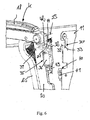
- the mechanical locking device 30 is - as from the Figures 5 and 6 is more apparent - formed by a on the support member 20 about a pivot axis extending in the vehicle transverse direction 31 pivotally mounted latch 32 which cooperates with a groove or slot-shaped locking recess 33 on the rear wall 11 of the operator's cab 5.
- an actuating slope 39 is formed in the region of the locking recess 33, which cooperates with the latch 32 when folding the support member 20.
- the mechanical locking device 30 is connected by means of an actuating device 35 designed as an electrical actuator 36 between a Release position and a locking position operable.
- the electrical actuator 36 is formed in the illustrated embodiment by a solenoid, which is fixed to the support member 20 and the linearly displaceable actuating tappet 37 actuates the latch 32.
- an operator-operable control device 38 for example a foot switch, can be arranged on the operator platform 10 to actuate the control device 38 to release the locking device when the picking truck 1 is stopped 30 to achieve.
- a monitoring device 40 For detecting the locking position and / or the release position of the locking device 30, a monitoring device 40 is provided, which has a release position and / or the locking position of the bolt 32 detecting sensor device 41, in particular a non-contact sensor device.
- the sensor device 41 is arranged on the rear wall 11 of the driver's station 5. In the illustrated embodiment, the sensor device 41 is arranged in the vertical direction below the lifting magnet.
- a transmission member 42 is arranged on the latch 32, which extends vertically down and at the bottom with a detection means 43, for example a magnet, provided for detecting the position of the bolt 32 by the sensor device 41 serves.
- On the transmission member 42 further comprises an actuating lug 44 is formed which serves to actuate the bolt 32 by the actuating plunger 37 of the solenoid.
- a further electronic monitoring device 50 is arranged, with which the pivoting of the existing of the three side barrier 16 -18 barrier assembly about the pivot axes S1 - S3 can be detected.
- the further monitoring device 50 has a sensor device 51, which detects the closed position and / or the open position of the middle side barrier 17, in particular a contactless sensor device, which is arranged on the carrier component 20.
- a Detection means 53 arranged, for example, a magnet which serves to detect the position of the central barrier 17 by the sensor device 51.
- a cover 60 is arranged on the carrier component 20.
- the cover 60 further extends in the direction of the rear wall 11 in order to cover the resulting gap between the rear wall 11 and the outwardly foldable support member 20 from above in the unfolded order picking position K of the carrier component 20.
- the carrier component 20 is shown with the cover 60 removed.
- the inventive, divided construction of the existing of the three side barriers 16-18 barrier assembly with the support member 20 and a arranged in the division of the barrier assembly pivot axis 21 allows for a simple structure and ergonomics ergonomic folding outward execution of the upper barrier strut 18th
- the folding function of the support member 20 is secured by the mechanical locking device 30 to prevent the folding of the barrier struts 18, 17 when driving the picking truck 1 or the lifting-lowering operation of the operator's cab 5.
- the picking process with outwardly extended to the picking position K support member 20 can only take place at standstill of the picking truck 1, in which the mechanical locking device 30 is unlocked by a powered solenoid, for example by operating the trained as a footswitch control device 38, in the release position.
- This deployment function of the carrier component 20 is monitored by the monitoring device 40 formed by the sensor device 41, which forms a safety monitoring of the mechanical locking device 30.
- the opening of the side barriers 16 - 18 is only permitted when the vehicle is at a standstill. This can be monitored in a simple manner by the monitoring device 50 formed by the sensor device 51.
- the operator can expand by simply leaning against the side barrier 18 with the body provided with the upper side barrier 18 and the middle side panel 17 support member 20 to the outside in the order picking K.
- the operator can if necessary move the upper side barrier 18 comfortably with the body out to the picking position K, for example, by leaning against the side barrier 18, wherein the operator has both hands for gripping the goods from the shelf free and can use ,
- the picking operation is further improved in terms of ergonomics and allows a high picking performance.
- the operator drives the provided with the upper side barrier 18 and the middle side panel 17 support member 20 spring assisted in the inner shut-A.
- the latch 32 which is not actuated by the solenoid, when folding the support member 20 are actuated in the inner shut-off position A, to ensure a locking in the locking recess 33.
- the range of the operator in the lateral direction and thus in the direction of a shelf during the picking process is significantly increased.
- An overstretching of the body in the direction of the shelf in the picking operation and when receiving the product from the shelf is avoided, so that an ergonomic picking operation is made possible by the folding movement L of the support member 20.
- greater shelf depths can be achieved by the operator during the picking process by the folding movement of the support member 20, whereby the storage areas better utilized and thus costs can be reduced.
- the release position or the locking position of the locking device 30 can be reliably detected and monitored, so that safe operation of the picking truck with a high level of operational safety during picking operation with locking device 30 located in the release position is made possible by appropriate intervention in the vehicle control ,
Landscapes
- Engineering & Computer Science (AREA)
- Transportation (AREA)
- Structural Engineering (AREA)
- Civil Engineering (AREA)
- Life Sciences & Earth Sciences (AREA)
- Geology (AREA)
- Mechanical Engineering (AREA)
- Lock And Its Accessories (AREA)
Claims (19)
- Chariot de préparation des commandes (1) comprenant un poste de conducteur (5) pouvant être soulevé et abaissé et au moins un dispositif d'arrêt (15) qui est formé de plusieurs armoires latérales (16, 17,18) et qui est disposé de manière à pouvoir pivoter dans la région de bord latéral du poste de travail du conducteur (F) réalisé dans le poste de conduite (5) entre une position ouverte essentiellement verticale et une position fermée essentiellement horizontale, caractérisé en ce que le dispositif d'arrêt (15) comprend une armoire latérale supérieure (18), une armoire latérale centrale (17) et une armoire latérale inférieure (16), l'armoire latérale supérieure (18) et l'armoire latérale centrale (17) étant disposées de manière à pouvoir pivoter au niveau d'un composant de support (20) entre la position ouverte et la position fermée, le composant de support (20) pouvant être rabattu vers l'extérieur entre une position d'arrêt (A) et une position de préparation des commandes (K) de manière limitée dans la direction latérale du chariot de préparation des commandes (1) autour d'un axe de pivotement horizontal (21) s'étendant dans la direction longitudinale du véhicule, et l'armoire latérale inférieure (16) étant disposée de manière à pouvoir pivoter au niveau du poste de conduite (5) entre la position fermée et la position ouverte et l'armoire latérale inférieure (16), lors du rabattement vers l'extérieur du composant de support (20), restant dans une position fixe sur le poste de conduite (5).
- Chariot de préparation des commandes (1) selon la revendication 1, caractérisé en ce qu'un dispositif de verrouillage (30) est prévu pour verrouiller le composant de support (20) dans la position d'arrêt (A).
- Chariot de préparation des commandes (1) selon la revendication 1 ou 2, caractérisé en ce que le composant de support (20) est disposé de manière à pouvoir être rabattu sur le poste de conduite (5) au moyen d'une articulation pivotante (22), en particulier d'une articulation de charnière, l'articulation pivotante (22) étant munie d'un dispositif de ressort intégré (23) qui sollicite le composant de support (20) dans la position d'arrêt (A).
- Chariot de préparation des commandes (1) selon l'une quelconque des revendications 1 à 3, caractérisé en ce que l'armoire latérale supérieure (18) et l'armoire latérale centrale (17) sont accouplées au moyen d'une tige d'accouplement (25) de manière à pouvoir pivoter conjointement entre la position fermée et la position ouverte.
- Chariot de préparation des commandes selon la revendication 4, caractérisé en ce que l'armoire latérale centrale (17) et l'armoire latérale inférieure (16) sont accouplés au moyen de la tige d'accouplement (25) de manière à pouvoir pivoter conjointement entre la position fermée et la position ouverte, une articulation pivotante supplémentaire (26), en particulier une articulation de charnière supplémentaire, en affleurement avec l'articulation de charnière (22) du composant de support (20) étant disposée dans la tige d'accouplement (25).
- Chariot de préparation des commandes selon l'une quelconque des revendications 3 à 5, caractérisé en ce que le dispositif de ressort (23) est formé par une plaque de ressort ou un ressort de torsion.
- Chariot de préparation des commandes (1) selon l'une quelconque des revendications 2 à 6, caractérisé en ce que le dispositif de verrouillage (30) est réalisé sous forme de dispositif de verrouillage mécanique.
- Chariot de préparation des commandes selon la revendication 7, caractérisé en ce que le dispositif de verrouillage mécanique présente un verrou (32) disposé de manière à pouvoir pivoter sur le composant de support (20), lequel coopère avec un évidement de verrouillage (33) sur le poste de conduite (5).
- Chariot de préparation des commandes selon la revendication 7 ou 8, caractérisé en ce que le dispositif de verrouillage mécanique peut être actionné au moyen d'un dispositif d'actionnement (35) entre une position de libération et une position de verrouillage.
- Chariot de préparation des commandes selon la revendication 9, caractérisé en ce que le dispositif d'actionnement (35) est formé par un dispositif d'actionnement électrique (36), en particulier un aimant de levage.
- Chariot de préparation des commandes selon la revendication 10, caractérisé en ce que le dispositif d'actionnement électrique (36) peut être actionné au moyen d'un dispositif de commande (38) pouvant être commandé par l'opérateur.
- Chariot de préparation des commandes selon la revendication 10 ou 11, caractérisé en ce que le dispositif d'actionnement électrique (36) est en liaison avec un dispositif de commande électronique, le dispositif de commande électronique étant réalisé de telle sorte qu'un actionnement du dispositif de verrouillage (30) dans la position de libération ne puisse s'effectuer qu'à l'arrêt du chariot de préparation des commandes.
- Chariot de préparation des commandes selon l'une quelconque des revendications 10 à 12, caractérisé en ce que le dispositif d'actionnement électrique (36) est en liaison avec un dispositif de commande électronique, le dispositif de commande électronique étant réalisé de telle sorte que pendant le mode de conduite du chariot de préparation des commandes (1) et/ou pendant le mode de levage ou d'abaissement du poste de conduite (5), un actionnement du dispositif de verrouillage (30) dans la position de libération soit bloqué.
- Chariot de préparation des commandes selon l'une quelconque des revendications 2 à 13, caractérisé en ce qu'un dispositif de surveillance (40) est prévu pour détecter la position de verrouillage et/ou la position de libération du dispositif de verrouillage (30).
- Chariot de préparation des commandes selon la revendication 14, caractérisé en ce que le dispositif de surveillance (40) présente un dispositif de capteur (41) détectant la position de libération et/ou la position de verrouillage du verrou (30), en particulier un dispositif de capteur sans contact.
- Chariot de préparation des commandes selon l'une quelconque des revendications 10 à 15, caractérisé en ce que le dispositif d'actionnement électrique (36) est disposé sur le composant de support (20) et le dispositif de capteur (41) est disposé sur le poste de conduite (5).
- Chariot de préparation des commandes selon la revendication 15 ou 16, caractérisé en ce que dans une position de libération du dispositif de verrouillage (30) détectée par le dispositif de capteur (41), un mode de conduite du chariot de préparation des commandes (1) et/ou un mode de levage ou d'abaissement du poste de conduite (5) est bloqué ou limité et dans une position de verrouillage du dispositif de verrouillage (30) détectée par le dispositif de capteur (41), un mode de conduite du chariot de préparation des commandes (1) et/ou un mode de levage ou d'abaissement du poste de conduite (5) est libéré.
- Chariot de préparation des commandes selon l'une quelconque des revendications 1 à 17, caractérisé en ce qu'au moyen d'un dispositif de surveillance supplémentaire (50), le pivotement des armoires latérales (16 ; 17 ; 18) peut être détecté.
- Chariot de préparation des commandes selon la revendication 18, caractérisé en ce que le dispositif de surveillance supplémentaire (50) présente un dispositif de capteur (51) détectant la position fermée et/ou la position ouverte des armoires latérales (16 ; 17 ; 18), en particulier un dispositif de capteur sans contact.
Applications Claiming Priority (1)
| Application Number | Priority Date | Filing Date | Title |
|---|---|---|---|
| DE201110018455 DE102011018455A1 (de) | 2011-04-21 | 2011-04-21 | Kommissionierflurförderzeug mit einem anhebbaren und absenkbaren Fahrerstand |
Publications (2)
| Publication Number | Publication Date |
|---|---|
| EP2514708A1 EP2514708A1 (fr) | 2012-10-24 |
| EP2514708B1 true EP2514708B1 (fr) | 2014-12-17 |
Family
ID=45841289
Family Applications (1)
| Application Number | Title | Priority Date | Filing Date |
|---|---|---|---|
| EP20120158588 Active EP2514708B1 (fr) | 2011-04-21 | 2012-03-08 | Chariot de commissionnement avec une cabine de conducteur qui peut être soulevé et abaissé |
Country Status (2)
| Country | Link |
|---|---|
| EP (1) | EP2514708B1 (fr) |
| DE (1) | DE102011018455A1 (fr) |
Cited By (2)
| Publication number | Priority date | Publication date | Assignee | Title |
|---|---|---|---|---|
| EP3263509A1 (fr) | 2016-06-30 | 2018-01-03 | Toyota Material Handling Manufacturing Sweden AB | Camion de ramassage d'ordre |
| EP3305714A1 (fr) | 2016-10-04 | 2018-04-11 | Toyota Material Handling Manufacturing Sweden AB | Chariot de préparation de commandes |
Families Citing this family (3)
| Publication number | Priority date | Publication date | Assignee | Title |
|---|---|---|---|---|
| EP2700609A1 (fr) * | 2012-08-23 | 2014-02-26 | BT Products AB | Camion industriel qui comprend une grille de protection pivotante |
| CN109941301B (zh) * | 2019-04-26 | 2024-02-23 | 中车眉山车辆有限公司 | 一种轨道车辆端部翻转式工作平台 |
| AU2021232056A1 (en) | 2020-03-06 | 2022-10-13 | Oshkosh Corporation | Lift device innovations |
Family Cites Families (4)
| Publication number | Priority date | Publication date | Assignee | Title |
|---|---|---|---|---|
| GB1056831A (en) * | 1963-01-11 | 1967-02-01 | Lansing Bagnall Ltd | Improvements in or relating to industrial lift trucks |
| US5011363A (en) * | 1989-12-05 | 1991-04-30 | Crown Equipment Corporation | Extend and retract control for fork lifts |
| GB2289669B (en) * | 1994-05-20 | 1997-12-17 | Lansing Linde Ltd | Industrial lift trucks |
| DE19839234A1 (de) * | 1998-08-28 | 2000-03-09 | Still Wagner Gmbh & Co Kg | Flurförderzeug mit anhebbarem Fahrerstand und Verfahren zum Betreiben des Flurförderzeugs |
-
2011
- 2011-04-21 DE DE201110018455 patent/DE102011018455A1/de not_active Withdrawn
-
2012
- 2012-03-08 EP EP20120158588 patent/EP2514708B1/fr active Active
Cited By (2)
| Publication number | Priority date | Publication date | Assignee | Title |
|---|---|---|---|---|
| EP3263509A1 (fr) | 2016-06-30 | 2018-01-03 | Toyota Material Handling Manufacturing Sweden AB | Camion de ramassage d'ordre |
| EP3305714A1 (fr) | 2016-10-04 | 2018-04-11 | Toyota Material Handling Manufacturing Sweden AB | Chariot de préparation de commandes |
Also Published As
| Publication number | Publication date |
|---|---|
| DE102011018455A1 (de) | 2012-10-25 |
| EP2514708A1 (fr) | 2012-10-24 |
Similar Documents
| Publication | Publication Date | Title |
|---|---|---|
| EP2994410B1 (fr) | Dispositif de chargement | |
| EP2514708B1 (fr) | Chariot de commissionnement avec une cabine de conducteur qui peut être soulevé et abaissé | |
| EP2641862B1 (fr) | Gerbeur à conducteur à pied | |
| EP2980004B1 (fr) | Toit protège-conducteur pouvant être abaissé | |
| DE2609711A1 (de) | Ausfahrbare abstuetzvorrichtung | |
| EP2805911B1 (fr) | Chariot de manutention, notamment chariot de préparation, avec poste de conduite relevable et abaissable | |
| WO2017036963A1 (fr) | Dispositif de chargement | |
| EP2165966B1 (fr) | Chariot de manutention doté d'un moyen de réception de charge comprenant au moins une section de charge repliable | |
| EP2511224B1 (fr) | Chariot de manutention pour rayonnage élevé, notamment chariot de commissionnement, doté d'un siège conducteur et d'accoudoirs latéraux | |
| DE102015114411B4 (de) | Frachtgut-Transportwagen | |
| DE69806316T2 (de) | Wagen mit Hubmast, geeignet zur Montage an das Ende eines Transportfahrzeugs | |
| EP2384951B1 (fr) | Timon d'un chariot de manutention | |
| EP3272699A1 (fr) | Empileur d'étagères | |
| EP1243490B1 (fr) | Chariot de manutention entraíné par batterie | |
| EP0309796B1 (fr) | Dispositif de sécurité pour chariots à fourche | |
| EP2383220B1 (fr) | Chariot de manutention doté d'un dispositif de commande | |
| EP2518005B1 (fr) | Chariot de manutention | |
| DE102015120041B4 (de) | Verfahren zur Ermittlung einer Notfallsituation einer Bedienperson eines mit einem Fahrerarbeitsplatz für die Bedienperson versehenen Flurförderzeugs | |
| EP2392540B1 (fr) | Chariot de manutention | |
| EP2308794B1 (fr) | Chariot de manutention commandé par timon, en particulier chariot élévateur | |
| DE102005013275A1 (de) | Niederhubwagen mit Rampenhubfunktion | |
| DE102010034454A1 (de) | Kommissionierflurförderzeug mit einem anhebbaren und absenkbaren Fahrerstand | |
| DE102016104745A1 (de) | Mitgängergeführter Hubwagen | |
| EP2518006B1 (fr) | Chariot de manutention doté d'un protège-conducteur | |
| DE3016157A1 (de) | Regalstapler fuer grosse hubhoehen |
Legal Events
| Date | Code | Title | Description |
|---|---|---|---|
| PUAI | Public reference made under article 153(3) epc to a published international application that has entered the european phase |
Free format text: ORIGINAL CODE: 0009012 |
|
| AK | Designated contracting states |
Kind code of ref document: A1 Designated state(s): AL AT BE BG CH CY CZ DE DK EE ES FI FR GB GR HR HU IE IS IT LI LT LU LV MC MK MT NL NO PL PT RO RS SE SI SK SM TR |
|
| AX | Request for extension of the european patent |
Extension state: BA ME |
|
| 17P | Request for examination filed |
Effective date: 20130418 |
|
| REG | Reference to a national code |
Ref country code: DE Ref legal event code: R079 Ref document number: 502012001815 Country of ref document: DE Free format text: PREVIOUS MAIN CLASS: B66F0009075000 Ipc: B66F0009120000 |
|
| GRAP | Despatch of communication of intention to grant a patent |
Free format text: ORIGINAL CODE: EPIDOSNIGR1 |
|
| RIC1 | Information provided on ipc code assigned before grant |
Ipc: B66F 9/075 20060101ALI20140801BHEP Ipc: B66F 9/12 20060101AFI20140801BHEP |
|
| INTG | Intention to grant announced |
Effective date: 20140826 |
|
| GRAS | Grant fee paid |
Free format text: ORIGINAL CODE: EPIDOSNIGR3 |
|
| GRAA | (expected) grant |
Free format text: ORIGINAL CODE: 0009210 |
|
| AK | Designated contracting states |
Kind code of ref document: B1 Designated state(s): AL AT BE BG CH CY CZ DE DK EE ES FI FR GB GR HR HU IE IS IT LI LT LU LV MC MK MT NL NO PL PT RO RS SE SI SK SM TR |
|
| REG | Reference to a national code |
Ref country code: GB Ref legal event code: FG4D Free format text: NOT ENGLISH |
|
| REG | Reference to a national code |
Ref country code: CH Ref legal event code: EP |
|
| REG | Reference to a national code |
Ref country code: IE Ref legal event code: FG4D Free format text: LANGUAGE OF EP DOCUMENT: GERMAN |
|
| REG | Reference to a national code |
Ref country code: AT Ref legal event code: REF Ref document number: 701734 Country of ref document: AT Kind code of ref document: T Effective date: 20150115 |
|
| REG | Reference to a national code |
Ref country code: DE Ref legal event code: R096 Ref document number: 502012001815 Country of ref document: DE Effective date: 20150129 |
|
| REG | Reference to a national code |
Ref country code: SE Ref legal event code: TRGR |
|
| PG25 | Lapsed in a contracting state [announced via postgrant information from national office to epo] |
Ref country code: NO Free format text: LAPSE BECAUSE OF FAILURE TO SUBMIT A TRANSLATION OF THE DESCRIPTION OR TO PAY THE FEE WITHIN THE PRESCRIBED TIME-LIMIT Effective date: 20150317 Ref country code: LT Free format text: LAPSE BECAUSE OF FAILURE TO SUBMIT A TRANSLATION OF THE DESCRIPTION OR TO PAY THE FEE WITHIN THE PRESCRIBED TIME-LIMIT Effective date: 20141217 Ref country code: FI Free format text: LAPSE BECAUSE OF FAILURE TO SUBMIT A TRANSLATION OF THE DESCRIPTION OR TO PAY THE FEE WITHIN THE PRESCRIBED TIME-LIMIT Effective date: 20141217 |
|
| REG | Reference to a national code |
Ref country code: LT Ref legal event code: MG4D |
|
| PG25 | Lapsed in a contracting state [announced via postgrant information from national office to epo] |
Ref country code: GR Free format text: LAPSE BECAUSE OF FAILURE TO SUBMIT A TRANSLATION OF THE DESCRIPTION OR TO PAY THE FEE WITHIN THE PRESCRIBED TIME-LIMIT Effective date: 20150318 Ref country code: HR Free format text: LAPSE BECAUSE OF FAILURE TO SUBMIT A TRANSLATION OF THE DESCRIPTION OR TO PAY THE FEE WITHIN THE PRESCRIBED TIME-LIMIT Effective date: 20141217 Ref country code: LV Free format text: LAPSE BECAUSE OF FAILURE TO SUBMIT A TRANSLATION OF THE DESCRIPTION OR TO PAY THE FEE WITHIN THE PRESCRIBED TIME-LIMIT Effective date: 20141217 Ref country code: RS Free format text: LAPSE BECAUSE OF FAILURE TO SUBMIT A TRANSLATION OF THE DESCRIPTION OR TO PAY THE FEE WITHIN THE PRESCRIBED TIME-LIMIT Effective date: 20141217 |
|
| PG25 | Lapsed in a contracting state [announced via postgrant information from national office to epo] |
Ref country code: NL Free format text: LAPSE BECAUSE OF FAILURE TO SUBMIT A TRANSLATION OF THE DESCRIPTION OR TO PAY THE FEE WITHIN THE PRESCRIBED TIME-LIMIT Effective date: 20141217 |
|
| PG25 | Lapsed in a contracting state [announced via postgrant information from national office to epo] |
Ref country code: RO Free format text: LAPSE BECAUSE OF FAILURE TO SUBMIT A TRANSLATION OF THE DESCRIPTION OR TO PAY THE FEE WITHIN THE PRESCRIBED TIME-LIMIT Effective date: 20141217 Ref country code: EE Free format text: LAPSE BECAUSE OF FAILURE TO SUBMIT A TRANSLATION OF THE DESCRIPTION OR TO PAY THE FEE WITHIN THE PRESCRIBED TIME-LIMIT Effective date: 20141217 Ref country code: CZ Free format text: LAPSE BECAUSE OF FAILURE TO SUBMIT A TRANSLATION OF THE DESCRIPTION OR TO PAY THE FEE WITHIN THE PRESCRIBED TIME-LIMIT Effective date: 20141217 Ref country code: SK Free format text: LAPSE BECAUSE OF FAILURE TO SUBMIT A TRANSLATION OF THE DESCRIPTION OR TO PAY THE FEE WITHIN THE PRESCRIBED TIME-LIMIT Effective date: 20141217 Ref country code: ES Free format text: LAPSE BECAUSE OF FAILURE TO SUBMIT A TRANSLATION OF THE DESCRIPTION OR TO PAY THE FEE WITHIN THE PRESCRIBED TIME-LIMIT Effective date: 20141217 |
|
| PG25 | Lapsed in a contracting state [announced via postgrant information from national office to epo] |
Ref country code: IS Free format text: LAPSE BECAUSE OF FAILURE TO SUBMIT A TRANSLATION OF THE DESCRIPTION OR TO PAY THE FEE WITHIN THE PRESCRIBED TIME-LIMIT Effective date: 20150417 Ref country code: PL Free format text: LAPSE BECAUSE OF FAILURE TO SUBMIT A TRANSLATION OF THE DESCRIPTION OR TO PAY THE FEE WITHIN THE PRESCRIBED TIME-LIMIT Effective date: 20141217 |
|
| REG | Reference to a national code |
Ref country code: DE Ref legal event code: R097 Ref document number: 502012001815 Country of ref document: DE |
|
| PLBE | No opposition filed within time limit |
Free format text: ORIGINAL CODE: 0009261 |
|
| STAA | Information on the status of an ep patent application or granted ep patent |
Free format text: STATUS: NO OPPOSITION FILED WITHIN TIME LIMIT |
|
| PG25 | Lapsed in a contracting state [announced via postgrant information from national office to epo] |
Ref country code: MC Free format text: LAPSE BECAUSE OF FAILURE TO SUBMIT A TRANSLATION OF THE DESCRIPTION OR TO PAY THE FEE WITHIN THE PRESCRIBED TIME-LIMIT Effective date: 20141217 Ref country code: DK Free format text: LAPSE BECAUSE OF FAILURE TO SUBMIT A TRANSLATION OF THE DESCRIPTION OR TO PAY THE FEE WITHIN THE PRESCRIBED TIME-LIMIT Effective date: 20141217 Ref country code: LU Free format text: LAPSE BECAUSE OF FAILURE TO SUBMIT A TRANSLATION OF THE DESCRIPTION OR TO PAY THE FEE WITHIN THE PRESCRIBED TIME-LIMIT Effective date: 20150308 |
|
| REG | Reference to a national code |
Ref country code: CH Ref legal event code: PL |
|
| 26N | No opposition filed |
Effective date: 20150918 |
|
| REG | Reference to a national code |
Ref country code: FR Ref legal event code: ST Effective date: 20151130 |
|
| REG | Reference to a national code |
Ref country code: IE Ref legal event code: MM4A |
|
| PG25 | Lapsed in a contracting state [announced via postgrant information from national office to epo] |
Ref country code: CH Free format text: LAPSE BECAUSE OF NON-PAYMENT OF DUE FEES Effective date: 20150331 Ref country code: LI Free format text: LAPSE BECAUSE OF NON-PAYMENT OF DUE FEES Effective date: 20150331 Ref country code: IE Free format text: LAPSE BECAUSE OF NON-PAYMENT OF DUE FEES Effective date: 20150308 |
|
| PG25 | Lapsed in a contracting state [announced via postgrant information from national office to epo] |
Ref country code: SI Free format text: LAPSE BECAUSE OF FAILURE TO SUBMIT A TRANSLATION OF THE DESCRIPTION OR TO PAY THE FEE WITHIN THE PRESCRIBED TIME-LIMIT Effective date: 20141217 Ref country code: FR Free format text: LAPSE BECAUSE OF NON-PAYMENT OF DUE FEES Effective date: 20150331 |
|
| PG25 | Lapsed in a contracting state [announced via postgrant information from national office to epo] |
Ref country code: MT Free format text: LAPSE BECAUSE OF FAILURE TO SUBMIT A TRANSLATION OF THE DESCRIPTION OR TO PAY THE FEE WITHIN THE PRESCRIBED TIME-LIMIT Effective date: 20141217 |
|
| REG | Reference to a national code |
Ref country code: DE Ref legal event code: R082 Ref document number: 502012001815 Country of ref document: DE Representative=s name: PATENTSHIP PATENTANWALTSGESELLSCHAFT MBH, DE |
|
| REG | Reference to a national code |
Ref country code: DE Ref legal event code: R082 Ref document number: 502012001815 Country of ref document: DE Representative=s name: PATENTSHIP PATENTANWALTSGESELLSCHAFT MBH, DE |
|
| PG25 | Lapsed in a contracting state [announced via postgrant information from national office to epo] |
Ref country code: HU Free format text: LAPSE BECAUSE OF FAILURE TO SUBMIT A TRANSLATION OF THE DESCRIPTION OR TO PAY THE FEE WITHIN THE PRESCRIBED TIME-LIMIT; INVALID AB INITIO Effective date: 20120308 Ref country code: BG Free format text: LAPSE BECAUSE OF FAILURE TO SUBMIT A TRANSLATION OF THE DESCRIPTION OR TO PAY THE FEE WITHIN THE PRESCRIBED TIME-LIMIT Effective date: 20141217 Ref country code: SM Free format text: LAPSE BECAUSE OF FAILURE TO SUBMIT A TRANSLATION OF THE DESCRIPTION OR TO PAY THE FEE WITHIN THE PRESCRIBED TIME-LIMIT Effective date: 20141217 |
|
| PG25 | Lapsed in a contracting state [announced via postgrant information from national office to epo] |
Ref country code: CY Free format text: LAPSE BECAUSE OF FAILURE TO SUBMIT A TRANSLATION OF THE DESCRIPTION OR TO PAY THE FEE WITHIN THE PRESCRIBED TIME-LIMIT Effective date: 20141217 |
|
| PG25 | Lapsed in a contracting state [announced via postgrant information from national office to epo] |
Ref country code: BE Free format text: LAPSE BECAUSE OF NON-PAYMENT OF DUE FEES Effective date: 20150331 Ref country code: PT Free format text: LAPSE BECAUSE OF FAILURE TO SUBMIT A TRANSLATION OF THE DESCRIPTION OR TO PAY THE FEE WITHIN THE PRESCRIBED TIME-LIMIT Effective date: 20150417 |
|
| PG25 | Lapsed in a contracting state [announced via postgrant information from national office to epo] |
Ref country code: TR Free format text: LAPSE BECAUSE OF FAILURE TO SUBMIT A TRANSLATION OF THE DESCRIPTION OR TO PAY THE FEE WITHIN THE PRESCRIBED TIME-LIMIT Effective date: 20141217 |
|
| PGFP | Annual fee paid to national office [announced via postgrant information from national office to epo] |
Ref country code: GB Payment date: 20180326 Year of fee payment: 7 |
|
| REG | Reference to a national code |
Ref country code: AT Ref legal event code: MM01 Ref document number: 701734 Country of ref document: AT Kind code of ref document: T Effective date: 20170308 |
|
| PG25 | Lapsed in a contracting state [announced via postgrant information from national office to epo] |
Ref country code: MK Free format text: LAPSE BECAUSE OF FAILURE TO SUBMIT A TRANSLATION OF THE DESCRIPTION OR TO PAY THE FEE WITHIN THE PRESCRIBED TIME-LIMIT Effective date: 20141217 |
|
| PG25 | Lapsed in a contracting state [announced via postgrant information from national office to epo] |
Ref country code: AT Free format text: LAPSE BECAUSE OF NON-PAYMENT OF DUE FEES Effective date: 20170308 |
|
| PG25 | Lapsed in a contracting state [announced via postgrant information from national office to epo] |
Ref country code: AL Free format text: LAPSE BECAUSE OF FAILURE TO SUBMIT A TRANSLATION OF THE DESCRIPTION OR TO PAY THE FEE WITHIN THE PRESCRIBED TIME-LIMIT Effective date: 20141217 |
|
| GBPC | Gb: european patent ceased through non-payment of renewal fee |
Effective date: 20190308 |
|
| PG25 | Lapsed in a contracting state [announced via postgrant information from national office to epo] |
Ref country code: GB Free format text: LAPSE BECAUSE OF NON-PAYMENT OF DUE FEES Effective date: 20190308 |
|
| P01 | Opt-out of the competence of the unified patent court (upc) registered |
Effective date: 20230507 |
|
| PGFP | Annual fee paid to national office [announced via postgrant information from national office to epo] |
Ref country code: IT Payment date: 20250331 Year of fee payment: 14 |
|
| PGFP | Annual fee paid to national office [announced via postgrant information from national office to epo] |
Ref country code: SE Payment date: 20260323 Year of fee payment: 15 |
|
| PGFP | Annual fee paid to national office [announced via postgrant information from national office to epo] |
Ref country code: DE Payment date: 20260320 Year of fee payment: 15 |