EP2514852A1 - Dispositif de transport pour un substrat formant film - Google Patents
Dispositif de transport pour un substrat formant film Download PDFInfo
- Publication number
- EP2514852A1 EP2514852A1 EP10837410A EP10837410A EP2514852A1 EP 2514852 A1 EP2514852 A1 EP 2514852A1 EP 10837410 A EP10837410 A EP 10837410A EP 10837410 A EP10837410 A EP 10837410A EP 2514852 A1 EP2514852 A1 EP 2514852A1
- Authority
- EP
- European Patent Office
- Prior art keywords
- substrate
- grip rollers
- film substrate
- film
- grip
- Prior art date
- Legal status (The legal status is an assumption and is not a legal conclusion. Google has not performed a legal analysis and makes no representation as to the accuracy of the status listed.)
- Withdrawn
Links
Images


Classifications
-
- B—PERFORMING OPERATIONS; TRANSPORTING
- B65—CONVEYING; PACKING; STORING; HANDLING THIN OR FILAMENTARY MATERIAL
- B65H—HANDLING THIN OR FILAMENTARY MATERIAL, e.g. SHEETS, WEBS, CABLES
- B65H23/00—Registering, tensioning, smoothing or guiding webs
- B65H23/02—Registering, tensioning, smoothing or guiding webs transversely
- B65H23/032—Controlling transverse register of web
- B65H23/0324—Controlling transverse register of web by acting on lateral regions of the web
-
- B—PERFORMING OPERATIONS; TRANSPORTING
- B65—CONVEYING; PACKING; STORING; HANDLING THIN OR FILAMENTARY MATERIAL
- B65H—HANDLING THIN OR FILAMENTARY MATERIAL, e.g. SHEETS, WEBS, CABLES
- B65H23/00—Registering, tensioning, smoothing or guiding webs
- B65H23/02—Registering, tensioning, smoothing or guiding webs transversely
- B65H23/032—Controlling transverse register of web
- B65H23/038—Controlling transverse register of web by rollers
-
- B—PERFORMING OPERATIONS; TRANSPORTING
- B65—CONVEYING; PACKING; STORING; HANDLING THIN OR FILAMENTARY MATERIAL
- B65H—HANDLING THIN OR FILAMENTARY MATERIAL, e.g. SHEETS, WEBS, CABLES
- B65H9/00—Registering, e.g. orientating, articles; Devices therefor
- B65H9/16—Inclined tape, roller, or like article-forwarding side registers
- B65H9/166—Roller
-
- B—PERFORMING OPERATIONS; TRANSPORTING
- B65—CONVEYING; PACKING; STORING; HANDLING THIN OR FILAMENTARY MATERIAL
- B65H—HANDLING THIN OR FILAMENTARY MATERIAL, e.g. SHEETS, WEBS, CABLES
- B65H2301/00—Handling processes for sheets or webs
- B65H2301/30—Orientation, displacement, position of the handled material
- B65H2301/32—Orientation of handled material
- B65H2301/323—Hanging
-
- B—PERFORMING OPERATIONS; TRANSPORTING
- B65—CONVEYING; PACKING; STORING; HANDLING THIN OR FILAMENTARY MATERIAL
- B65H—HANDLING THIN OR FILAMENTARY MATERIAL, e.g. SHEETS, WEBS, CABLES
- B65H2403/00—Power transmission; Driving means
- B65H2403/90—Machine drive
- B65H2403/94—Other features of machine drive
- B65H2403/942—Bidirectional powered handling device
-
- B—PERFORMING OPERATIONS; TRANSPORTING
- B65—CONVEYING; PACKING; STORING; HANDLING THIN OR FILAMENTARY MATERIAL
- B65H—HANDLING THIN OR FILAMENTARY MATERIAL, e.g. SHEETS, WEBS, CABLES
- B65H2404/00—Parts for transporting or guiding the handled material
- B65H2404/10—Rollers
- B65H2404/14—Roller pairs
- B65H2404/142—Roller pairs arranged on movable frame
- B65H2404/1421—Roller pairs arranged on movable frame rotating, pivoting or oscillating around an axis, e.g. parallel to the roller axis
- B65H2404/14212—Roller pairs arranged on movable frame rotating, pivoting or oscillating around an axis, e.g. parallel to the roller axis rotating, pivoting or oscillating around an axis perpendicular to the roller axis
Definitions
- the present invention relates to a film substrate conveying device for conveying a film substrate (referred to as "substrate” hereinafter) while placing the film substrate upright, with one end part thereof being on an upper side with respect to a width direction thereof.
- a device for manufacturing a thin-film laminated body (referred to as “manufacturing device” hereinafter) is used for forming, on a surface of a substrate, a photoelectric conversion layer composed of a thin-film photoelectric conversion element.
- This manufacturing device is configured to hermetically form the substrate within a film-forming chamber thereof. Furthermore, in order to convey the substrate into the film-forming chamber, the substrate wound by an unwinding core is dispatched toward the film-forming chamber, passes through the film-forming chamber, and then wound by a winding core.
- a substrate conveying method of a film substrate conveying device (referred to as "conveying device” hereinafter) provided mainly in the above-described manufacturing device, an upright conveying method is adopted where a substrate is conveyed while being placed upright, with one end part thereof being on upper side with respect to a width direction thereof.
- a conveying device using this upright conveying method is excellent in terms of preventing contamination of the substrate because particles cannot accumulate on the surface of the substrate, and in terms of reducing the space of the manufacturing device by placing the substrate upright. Meanwhile, the substrate is pulled and held mainly between the unwinding core and winding core. Therefore, the substrate tends to be weighed down and might meander in the width direction.
- the position of the substrate is displaced in the width direction, causing warpage of the substrate in the width direction. Stress is concentrated unevenly in the substrate due to this warpage, causing wrinkles on the substrate. Due to the wrinkles, the characteristics of the thin-film photoelectric conversion element and the like formed on the substrate deteriorate.
- Patent Document 1 the structure disclosed in Patent Document 1 is adopted in which grip rollers for adjusting the position of a substrate in a width direction are provided in a conveying device for conveying the substrate in a forward feed direction.
- the plurality of pairs of grip rollers are provided in a manner as to sandwich an upper end part and a lower end part of the substrate.
- the pair of grip rollers holding the upper end part is tilted upward with respect to the forward feed direction of the substrate, whereas the pair of grip rollers holding the lower end part is tilted downward with respect to the forward feed direction of the substrate.
- Patent Document 1 is designed to enhance the gripping force of the pairs of grip rollers by increasing the force of the grip rollers sandwiching the substrate therebetween (referred to as "substrate sandwiching force" hereinafter), in order to deal with the deterioration of the elastic body.
- Patent Document 1 Japanese Patent Application Publication No. 2009-38276
- Patent Document 1 when increasing the substrate sandwiching force of the grip rollers that is obtained by the elastic body on the outer circumferential surface, the elastic body on the outer circumferential surface might be squashed, changing the shape of the cross-section of the outer circumferential surface into an ellipse, as well as the diameter of the grip rollers. In such a case, a desired gripping force and adequate lifting force for lifting up the substrate cannot be obtained, which makes it difficult to move the substrate to a desired position. This leads to a decrease of the accuracy of adjusting the position of the substrate.
- the present invention was contrived in view of the circumstances described above, and an object thereof is to provide a film substrate conveying device capable of adjusting, with a high degree of accuracy, the position of each of substrates conveyed in both a forward feed direction and a backward feed direction.
- a film substrate conveying device of the present invention is a film substrate conveying device for conveying a belt-like film substrate while placing the film substrate upright, with one end part thereof being on an upper side in a width direction thereof, this film substrate conveying device having: at least a pair of first grip rollers that is disposed so as to sandwich an upper end part of the film substrate therebetween; and a first angle adjusting mechanism that is capable of adjusting an inclination direction and an inclination angle of the first grip rollers so as to be able to incline a rotation axis angle of the first grip rollers such that a rotation direction of the first grip rollers is on an upper side with respect to a conveying direction.
- the film substrate conveying device further has: at least a pair of second grip rollers that is disposed so as to sandwich a lower end part of the film substrate therebetween; and a second angle adjusting mechanism that is capable of adjusting an inclination direction and an inclination angle of the second grip rollers so as to be able to incline a rotation axis angle of the second grip rollers such that a rotation direction of the second grip rollers is on a lower side with respect to the conveying direction.
- the film substrate conveying device further has detection means for detecting a level of a width direction end part of the film substrate, wherein when the detection means detects a displacement of the film substrate, the first angle adjusting mechanism and/or the second angle adjusting mechanism performs control to incline the first grip rollers and/or the second grip rollers in an inclination direction corresponding to the conveying direction of the film substrate.
- the first angle adjusting mechanism and/or the second angle adjusting mechanism performs control to change the inclination angle of the first grip rollers and/or the second grip rollers in order to correct the displacement of the substrate.
- the film substrate conveying device of the present invention can accomplish the following effects.
- the film substrate conveying device according to the present invention is a film substrate conveying device for conveying a belt-like film substrate while placing the film substrate upright, with one end part thereof being on an upper side in a width direction thereof and conveying the film substrate, the film substrate conveying device having: at least a pair of first grip rollers that is disposed so as to sandwich an upper end part of the film substrate therebetween; and a first angle adjusting mechanism that is capable of adjusting an inclination direction and an inclination angle of the first grip rollers so as to be able to incline a rotation angle of the first grip rollers such that a rotation direction of the first grip rollers is on an upper side with respect to a conveying direction.
- the film substrate conveying device further has: at least a pair of second grip rollers that is disposed so as to sandwich a lower end part of the film substrate therebetween; and a second angle adjusting mechanism that is capable of adjusting an inclination direction and an inclination angle of the second grip rollers, so as to be able to incline a rotation angle of the second grip rollers such that a rotation direction of the second grip rollers is on a lower side with respect to the conveying direction.
- the film substrate conveying device further has detection means for detecting a level of a width direction end part of the film substrate, wherein when the detection means detects a displacement of the film substrate, the first angle adjusting mechanism and/or the second angle adjusting mechanism performs control to incline the first grip rollers and/or the second grip rollers in the inclination direction corresponding to the conveying direction of the film substrate. In this manner, the position of the film substrate conveyed in the forward feed direction and the backward feed direction can be adjusted with a high degree of accuracy.
- the first angle adjusting mechanism and/or the second angle adjusting mechanism performs control to change the inclination angle of the first grip rollers and/or the second grip rollers in order to correct the displacement of the substrate. For instance, when the gripping force of the first grip rollers weakens due to the wear of the first grip rollers, and adequate lifting force for lifting the film substrate cannot be obtained, the position of the film substrate can be corrected by increasing the inclination of the first grip rollers and the distance in which the film substrate moves in the width direction. As a result, imposing an excess load onto the film substrate can be inhibited without increasing the force of the first grip rollers sandwiching the film substrate.
- the position of the film substrate can be corrected by reducing the inclination of the first grip rollers and the distance in which the film substrate moves in the width direction. As a result, the accuracy of adjusting the position of the film substrate can be prevented from dropping.
- a film substrate conveying device according to a first embodiment of the present invention is described hereinafter.
- a device for manufacturing a thin-film laminated body referred to as “manufacturing device” hereinafter
- a belt-like film substrate referred to as “substrate” hereinafter
- substrate 2 is placed upright with one end part thereof being on an upper side in a width direction thereof, and then conveyed.
- a thin film is then formed on a surface of the substrate 2.
- the first embodiment illustrates a situation in which the width direction of the substrate 2 follows a perpendicular direction, but the present invention is not limited thereto.
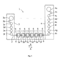
- the manufacturing device 1 is provided with an unwinding chamber 3 for unwinding the substrate 2 and a winding chamber 4 for winding the substrate 2.
- Six film-forming chambers 5a to 5f, for example, are provided between the unwinding chamber 3 and the winding chamber 4.
- the substrate 2 can be conveyed in a forward feed direction from the unwinding chamber 3 to the winding chamber 4 (shown by an arrow A in the diagram), and a backward feed direction from the winding chamber 4 to the unwinding chamber 3 (shown by an arrow B in the diagram).
- a conveying section between the unwinding chamber 3 and the film-forming chamber 5a, conveying sections between the five adjacent film-forming chambers, and a conveying section between the winding chamber 4 and the film-forming chamber 5f, are each provided with, for example, a pair of first grip rollers 6.
- An unwinding core 3a capable of unwinding the wound substrate 2 is provided on the inside of the unwinding chamber 3, in a manner as to be able to be able to rotate around its own rotation axis that is along the width direction of the substrate 2.
- Five rollers 3b to 3f, for example, driven to convey the substrate 2 and controlling the tension thereof are provided on the inside of the unwinding chamber 3 and on a forward feed direction downstream side from the unwinding core 3a, in a manner as to be able to rotate around their own rotation axes that are along the width direction of the substrate 2.
- the unwinding core 3a and the rollers 3b to 3f are configured to rotate in a manner as to be able to convey the substrate 2 in the forward feed direction and the backward feed direction.
- rollers provided to be driven for conveying the substrate 2 and controlling the tension thereof as shown in Fig. 1 is merely an example and may not only be the number described above, but also any number that can be changed in accordance with specifications of the manufacturing device 1. It is not necessary to provide the rollers driven to convey the substrate 2 and controlling the tension thereof.
- a winding core 4a capable of winding the substrate 2 is provided on the inside of the winding chamber 4, in a manner as to be able to rotate around its own rotation axis that is along the width direction of the substrate 2.
- Seven rollers 4b to 4h for conveying the substrate 2 and controlling the tension thereof are provided, as an example, on the inside of the winding chamber 4 and on a forward feed direction upstream side from the winding core 4a, in a manner as to be able to rotate around their own rotation axes that are along the width direction of the substrate 2.
- the winding core 4a and the rollers 4b to 4h are configured to rotate in a manner as to be able to convey the substrate 2 in the forward feed direction and the backward feed direction.
- rollers provided for conveying the substrate 2 and controlling the tension thereof as shown in Fig. 1 is merely an example and may not only be the number described above, but also any number that can be changed in accordance with the specifications of the manufacturing device 1. It is not necessary to provide the rollers for conveying the substrate 2 and controlling the tension thereof.
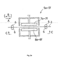
- FIGs. 2(a) and 2(b) A structure of each of the film-forming chambers 5a to 5f is described with reference to Figs. 2(a) and 2(b) .
- the substrate 2 is fed in the forward feed direction (the arrow A), and the first grip rollers 6 are accommodated to the substrate 2 fed in the forward feed direction.
- High-voltage electrodes 7a to 7f and ground electrodes 8a to 8f are placed, face-to-face, in the film-forming chambers 5a to 5f, respectively.
- the substrate 2 passes through between each of the high-voltage electrodes 7a to 7f and each of the ground electrodes 8a to 8f.
- the high-voltage electrodes 7a to 7f and the ground electrodes 8a to 8f are shorter, in the width direction of the substrate 2, than the width of the substrate 2.
- the thin-film laminated body is not formed neither an upper end part nor a lower end part of the substrate 2 in the width direction.
- Film formation gas is supplied into the film-forming chambers 5a to 5f.
- the film-forming chambers 5a to 5f can be kept hermetic. In these film-forming chambers 5a to 5f, the thin film is formed on the substrate 2 when the substrate 2 is positioned between each of the high-voltage electrodes 7a to 7f and each of the ground electrodes 8a to 8f.
- Examples of a method for forming a film on the surface of the substrate 2 include CVD (Chemical Vapor Deposition), PVD (Physical Vapor Deposition) and the like.
- CVD Chemical Vapor Deposition
- PVD Physical Vapor Deposition
- the number of film-forming chambers shown in Fig. 1 is used an example, and is not limited to the one described above and can be changed in accordance with the specifications of the manufacturing device 1.
- a heat chamber for heating the substrate 2 may be provided.
- the manufacturing device 1 is further provided with detection means 9 for detecting the position of the substrate 2 in the width direction.
- the detection means 9 may be configured to be able to detect, for example, the position of an edge part of the substrate 2 in the width direction.
- the detection means 9 be a noncontact sensor or, for example, a transmission-type laser sensor or a reflective photosensor.
- the detection means 9 is connected to control means 10.
- Each pair of first grip rollers 6 is configured to be able to rotate around rotation axes 6a thereof, and is placed between the adjacent film-forming chambers, in a manner as to sandwich the upper end part of the substrate 2 therebetween. In other words, the pair of first grip rollers 6 sandwiches a section of the substrate 2 that does not have the thin-film laminated body formed thereon.
- An outer circumferential surface 6b of each of the first grip rollers 6 may be formed of an elastic body. Examples of the elastic body include silicon rubber, fluorine rubber, and other heat-resistant rubbers.
- each of the first grip rollers 6 may be formed of a synthetic resin such as PTFE and polyimide or may be formed of a material applied with stainless steel, iron, or chrome.
- the outer circumferential surface 6b of each of the first grip rollers 6 may be formed of any materials as long as predetermined performances such as a force for protecting and gripping the substrate 2 can be obtained.
- the first grip rollers 6 are configured to be able to adjust the inclination thereof.
- a first angle adjusting mechanism 11 for adjusting the inclination of the first grip rollers 6 is described with reference to Figs. 3(a) to 3(c) . As shown in Figs. 3(a) to 3(c) , by mean of the first angle adjusting mechanism 11, the rotation axis 6a of each of the first grip rollers 6 is adjusted to be placed neutrally along the width direction of the substrate 2.
- a roller shaft 6c is disposed in the first grip roller 6, in a manner as to extend upward from an upper end of the first grip roller 6 along the width direction of the substrate 2. An upper end of the roller shaft 6c is attached rotatably to a roller attachment part 12.
- a link 13 is also disposed in a manner as to extend upward from the roller attachment part 12 along the width direction of the substrate 2.
- An upper part of the link 13 is provided with an engaging roller 14.
- a link attachment part 13a is provided in the middle of the width direction of the substrate 2, which is located between the roller attachment part 12 and the engaging roller 14.
- This link attachment part 13a is configured to be able to rotate the link 13 around a link rotation axis 13b that extends in the width direction with respect to the surface of the substrate 2, and is attached to a supporting part 15. Therefore, the link 13 can rotate with respect to the supporting part 15.
- biasing means 16 is disposed between the link 13 and the supporting part 15 and along a conveying direction of the substrate 2. This biasing means 16 may be configured to be able to return the link 13 to a neutral position thereof, by using a coil spring, a plate spring, a torsion spring, a rubber member or the like.
- An actuator 17 is disposed above the link 13.
- the actuator 17 has an arm 18 that is placed along the width direction with respect to the surface of the substrate 2.
- a tip end part 18a of the arm 18 is engaged with the engaging roller 14 attached to the link 13.
- a rotating shaft 19 extending along the width direction of the substrate 2 is attached to a base end part 18b of the arm 18.
- a lower end of the rotating shaft 19 is attached to the base end part 18b of the arm 18, and an upper end of the rotating shaft 19 is attached to a drive source 20. Therefore, the arm 18 can be rotated by the rotary drive of the drive source 20.
- this drive source 20 is supported by the supporting part 15, and the drive source 20 of the actuator 17 is connected to the control means 10.
- Adjusting the position of the substrate 2 conveyed in the forward feed direction is described with reference to Figs. 4(a), 4(b) and 5 .
- the detection means 9 detects a downward displacement of the substrate 2 conveyed in the forward feed direction
- the detection means 9 sends a signal to the control means 10 (see Fig. 2(b) ).
- the control means 10 sends the signal to the drive source 20 of the actuator 17, and the drive source 20 is subjected to rotation control such that the tip end part 18a of the arm 18 is moved in toward the backward feed direction.
- the engaging roller 14 that is engaged with the tip end part 18a of the arm 18 also moves toward the backward feed direction, and the link 13 rotates around the link rotation axis 13b.
- the first grip rollers 6 are inclined by an inclination angle ⁇ 1 with respect to the width direction of the substrate 2 such that the lower sides of the first grip rollers 6 are directed toward the forward feed direction along the surface of the substrate 2.
- the first grip rollers 6 are inclined upward with respect to the forward feed direction of the substrate 2. Note that in the state in which the first grip rollers 6 are inclined by the inclination angle ⁇ 1 , the link 13 is biased by the biasing means 16 such that the first grip rollers 6 are returned to a neutral position thereof.
- Adjusting the position of the substrate 2 conveyed in the backward feed direction is described with reference to Figs. 6(a), 6(b) and 7 .
- the detection means 9 detects a downward displacement of the substrate 2 conveyed in the backward feed direction
- the detection means 9 sends a signal to the control means 10 (see Fig. 2(b) ).
- the control means 10 sends the signal to the drive source 20 of the actuator 17, and the drive source 20 is subjected to rotation control such that the tip end part 18a of the arm 18 is moved in toward the forward feed direction.
- the engaging roller 14 that is engaged with the tip end part 18a of the arm 18 also moves toward the forward feed direction, and the link 13 rotates around the link rotation axis 13b.
- the first grip rollers 6 are inclined by an inclination angle ⁇ 2 with respect to the width direction of the substrate 2 such that the lower sides of the first grip rollers 6 are directed toward the backward feed direction along the surface of the substrate 2.
- the first grip rollers 6 are inclined upward with respect to the backward feed direction of the substrate 2. Note that in the state in which the first grip rollers 6 are inclined by the inclination angle ⁇ 2 , the link 13 is biased by the biasing means 16 such that the first grip rollers 6 are returned to the neutral position thereof.
- the control means 10 controls the drive source 20 of the actuator 17, in a manner as to increase the inclination angle ⁇ 1 or ⁇ 2 of the first grip rollers 6. As a result, the position of the substrate 2 is corrected.
- the control means 10 controls the drive source 20 of the actuator 17, in a manner as to reduce the inclination angle ⁇ 1 or ⁇ 2 of the first grip rollers 6. As a result, the position of the substrate 2 is corrected.
- a device for manufacturing a thin-film laminated body according to a second embodiment of the present invention is described hereinafter.
- the basic configuration of the device for manufacturing a thin-film laminated body according to the second embodiment is the same as that of the device for manufacturing a thin-film laminated body according to the first embodiment.
- the same reference numerals and names as those of the first embodiment are used to describe the same components of the first embodiment.
- the configurations that are different than those of the first embodiment are now described.
- a pair of second grip rollers 6' is further provided in a manner as to sandwich the lower end part of the substrate 2 therebetween.
- each of the second grip rollers 6' has a rotation axis 6a' and an outer circumferential surface 6b'.
- a second angle adjusting mechanism capable of adjusting an inclination direction and an inclination angle of the second grip rollers 6' is provided to incline the second grip rollers 6' downward with respect to the conveying direction and toward both the forward feed direction and the backward feed direction with respect to the conveying direction, with the outer circumferential surfaces 6b positioned along the surface of the substrate 2.
- This second angle adjusting mechanism corresponds to the second grip rollers 6' and has the basic configuration as the first angle adjusting mechanism 11.
- Fig. 8 shows a state in which the substrate 2 is fed in the forward feed direction (the arrow A) and upper sides of the second grip rollers 6' are inclined in the forward feed direction so as to correspond to the substrate 2 fed in the forward feed direction.
- the inclination direction and the inclination angle of the first and/or second grip rollers 6, 6' are adjusted by the first angle adjusting mechanism 11 and/or the second angle adjusting mechanism, in a manner that the first and/or second grip rollers 6, 6' are inclined toward both the forward feed direction and the backward feed direction in the conveying direction of the substrate 2.
- the position of the substrate 2 conveyed in the forward feed direction and the backward feed direction can be adjusted with a high degree of accuracy.
- the position of the substrate 2 can be corrected by increasing the inclination of the first grip rollers 6 and the distance in which the substrate 2 moves in the width direction. As a result, imposing an excess load onto the substrate 2 can be inhibited without increasing the force of the first grip rollers 6 sandwiching the substrate 2.
- the position of the substrate 2 can be corrected by reducing the inclination of the first grip rollers 6 and the distance in which the substrate 2 moves in the width direction. As a result, the accuracy of adjusting the position of the substrate 2 can be prevented from dropping.
- the first and/or second grip rollers 6, 6' may be configured such that the force thereof for sandwiching the substrate 2 therebetween (referred to as "substrate sandwiching force" hereinafter) can be adjusted.
- substrate sandwiching force the force thereof for sandwiching the substrate 2 therebetween
- the control means 10 may control the pair of first grip rollers 6 to correct the position of the substrate 2, in a manner as to increase the substrate sandwiching force of the pair of first grip rollers 6.
- control means 10 may control the pair of first grip rollers 6 to correct the position of the substrate 2, in a manner as to reduce the substrate sandwiching force of the pair of first grip rollers 6. In this manner, the same effects as those of the present invention can be obtained.
- the first and/or second grip rollers 6, 6' may be provided in at least one conveying section out of the conveying section between the unwinding chamber 3 and the film-forming chamber 5a, the conveying sections between the five adjacent film-forming chambers, and the conveying section between the winding chamber 4 and the film-forming chamber 5f.
- the number of conveying sections provided with the first and/or second grip rollers 6, 6' can be changed such that the position of the substrate 2 can be adjusted appropriately.
- the number of the first and/or second grip rollers 6, 6' provided in each conveying section may be two or more. In this manner, the same effects as those of the present invention can be obtained.
- a drive source for rotating the first and/or second grip rollers 6, 6' may be provided so that the first and/or second grip rollers 6, 6' can be rotated by this drive source.
- This drive source may be connected to the control means 10 to rotate the first and/or second grip rollers 6, 6'.
- the substrate sandwiching force of a pair of the first grip rollers 6 was set at 4.4 N, 8.9 N or 16.3 N, and changes in a lifting force F of the pair of first grip rollers 6 (referred to as "lifting force” hereinafter) for lifting up the substrate 2 were measured when the inclination angle ⁇ 1 or ⁇ 2 of the first grip rollers 6 was changed between 0° to 8°.
- Fig. 9 shows a relationship between the inclination angle ⁇ 1 or ⁇ 2 of the first grip rollers 6 and the lifting force F of the first grip roller 6 for lifting up the substrate 2, wherein a solid line P shows that the substrate sandwiching force is 4.4 N, a dashed line Q shows that the substrate sandwiching force is 8.9 N, and a chain line R shows that the substrate sandwiching force is 16.3 N.
- the lifting force F increases in proportion to the inclination angle ⁇ 1 or ⁇ 2 .
- the inclination angle ⁇ 1 or ⁇ 2 may be approximately 3.5°.
- the inclination angle ⁇ 1 or ⁇ 2 may be approximately 2°.
- the inclination angle ⁇ 1 or ⁇ 2 may be approximately 1°.
Landscapes
- Engineering & Computer Science (AREA)
- Mechanical Engineering (AREA)
- Container, Conveyance, Adherence, Positioning, Of Wafer (AREA)
- Physical Vapour Deposition (AREA)
- Chemical Vapour Deposition (AREA)
- Registering, Tensioning, Guiding Webs, And Rollers Therefor (AREA)
- Advancing Webs (AREA)
Applications Claiming Priority (2)
| Application Number | Priority Date | Filing Date | Title |
|---|---|---|---|
| JP2009282865A JP5652692B2 (ja) | 2009-12-14 | 2009-12-14 | フィルム基板の搬送装置 |
| PCT/JP2010/070787 WO2011074381A1 (fr) | 2009-12-14 | 2010-11-22 | Dispositif de transport pour un substrat formant film |
Publications (2)
| Publication Number | Publication Date |
|---|---|
| EP2514852A1 true EP2514852A1 (fr) | 2012-10-24 |
| EP2514852A4 EP2514852A4 (fr) | 2013-10-09 |
Family
ID=44167144
Family Applications (1)
| Application Number | Title | Priority Date | Filing Date |
|---|---|---|---|
| EP10837410.9A Withdrawn EP2514852A4 (fr) | 2009-12-14 | 2010-11-22 | Dispositif de transport pour un substrat formant film |
Country Status (5)
| Country | Link |
|---|---|
| US (1) | US20130043294A1 (fr) |
| EP (1) | EP2514852A4 (fr) |
| JP (1) | JP5652692B2 (fr) |
| CN (1) | CN102770579A (fr) |
| WO (1) | WO2011074381A1 (fr) |
Families Citing this family (11)
| Publication number | Priority date | Publication date | Assignee | Title |
|---|---|---|---|---|
| KR102090712B1 (ko) * | 2013-07-25 | 2020-03-19 | 삼성디스플레이 주식회사 | 박막 증착 장치와, 이를 이용한 증착 방법 및 유기 발광 표시 장치의 제조 방법 |
| CN105506553B (zh) * | 2014-09-26 | 2019-03-12 | 蒯一希 | 真空镀膜装置、真空双面镀膜装置及带材的位置调整方法 |
| CN104805400B (zh) * | 2015-04-10 | 2017-09-29 | 宁波华甬新材料科技有限公司 | 用于薄膜沉积设备系统的样品传递和掩膜装置 |
| CN106115336A (zh) * | 2016-08-23 | 2016-11-16 | 温州瑞驰机械有限公司 | 拉伸膜纠偏装置 |
| ES2945717T3 (es) | 2017-10-10 | 2023-07-06 | Bobst Grenchen Ag | Dispositivo de alineación de hojas, máquina para procesar una hoja, así como procedimiento para alinear una hoja |
| CN108666612B (zh) * | 2018-07-27 | 2024-03-01 | 重庆能源职业学院 | 用于蓄电池的撕膜及清洗风干装置 |
| CN112125007A (zh) * | 2020-09-29 | 2020-12-25 | 山东新北洋信息技术股份有限公司 | 纠偏装置、薄片类介质处理设备和纠偏装置的控制方法 |
| EP4334228A4 (fr) * | 2021-05-06 | 2025-04-16 | Applied Materials, Inc. | Mesure et commande de tension de bande transversale |
| DE102022129119A1 (de) * | 2022-11-03 | 2024-05-08 | Syntegon Technology Gmbh | Querverfahreinheit für eine Vorrichtung zur Herstellung von Verpackungselementen aus faserbasierten Materialien |
| CN115971140B (zh) * | 2023-03-20 | 2023-07-21 | 山东金冠网具有限公司 | 一种渔业养殖网清洗机 |
| WO2025165397A1 (fr) | 2024-01-29 | 2025-08-07 | Kohlam, Llc | Dispositif d'alignement de composite multicouche |
Family Cites Families (11)
| Publication number | Priority date | Publication date | Assignee | Title |
|---|---|---|---|---|
| US5653929A (en) * | 1995-08-25 | 1997-08-05 | E. I. Du Pont De Nemours And Company | Process for preparing a photopolymerizable printing element |
| JPH09130023A (ja) * | 1995-10-27 | 1997-05-16 | Fujitsu Ltd | ドライフィルムラミネータ |
| DE10154884C5 (de) * | 2001-11-05 | 2009-11-19 | Gebr. Schmid Gmbh & Co. | Vorrichtung zum Transport von flexiblem Flachmaterial, insbesondere Leiterplatten |
| JP4060734B2 (ja) * | 2003-03-06 | 2008-03-12 | Tdk株式会社 | 搬送方法、搬送装置、塗布方法及び塗布物製造方法 |
| EP2020392B1 (fr) * | 2007-08-03 | 2013-10-23 | Fuji Electric Co., Ltd. | Appareil pour la fabrication d'un élément stratifié à film mince |
| JP2009038276A (ja) | 2007-08-03 | 2009-02-19 | Fuji Electric Systems Co Ltd | 薄膜積層体の製造装置 |
| JP2009038277A (ja) * | 2007-08-03 | 2009-02-19 | Fuji Electric Systems Co Ltd | 薄膜積層体の製造装置 |
| JP2009057632A (ja) * | 2007-08-03 | 2009-03-19 | Fuji Electric Holdings Co Ltd | 薄膜積層体の製造装置 |
| JP5018523B2 (ja) * | 2008-02-07 | 2012-09-05 | 富士電機株式会社 | 薄膜積層体の製造装置 |
| WO2009122836A1 (fr) * | 2008-03-31 | 2009-10-08 | 富士電機システムズ株式会社 | Equipement et procédé de production de stratifiés à films minces |
| EP2511210A1 (fr) * | 2009-12-11 | 2012-10-17 | Fuji Electric Co., Ltd. | Appareil destiné au transfert de substrat souple |
-
2009
- 2009-12-14 JP JP2009282865A patent/JP5652692B2/ja not_active Expired - Fee Related
-
2010
- 2010-11-22 WO PCT/JP2010/070787 patent/WO2011074381A1/fr not_active Ceased
- 2010-11-22 EP EP10837410.9A patent/EP2514852A4/fr not_active Withdrawn
- 2010-11-22 US US13/512,213 patent/US20130043294A1/en not_active Abandoned
- 2010-11-22 CN CN201080053146.2A patent/CN102770579A/zh active Pending
Also Published As
| Publication number | Publication date |
|---|---|
| CN102770579A (zh) | 2012-11-07 |
| EP2514852A4 (fr) | 2013-10-09 |
| JP2011122225A (ja) | 2011-06-23 |
| WO2011074381A1 (fr) | 2011-06-23 |
| JP5652692B2 (ja) | 2015-01-14 |
| US20130043294A1 (en) | 2013-02-21 |
Similar Documents
| Publication | Publication Date | Title |
|---|---|---|
| EP2514852A1 (fr) | Dispositif de transport pour un substrat formant film | |
| US20120031565A1 (en) | Flexible substrate position control device | |
| US8746309B2 (en) | Position controller for flexible substrate | |
| JP2009038276A (ja) | 薄膜積層体の製造装置 | |
| JP5765240B2 (ja) | 帯状のシート基板のための搬送装置及び処理装置、デバイス製造方法 | |
| JP5423808B2 (ja) | 可撓性基板の搬送装置 | |
| KR102048852B1 (ko) | 액티브 댄서를 이용한 웹 좌우 장력 독립 제어 장치 및 방법 | |
| WO2010073955A1 (fr) | Dispositif de traitement d'un substrat souple | |
| CN101359585B (zh) | 用于制造薄膜层叠件的设备 | |
| CN110697476A (zh) | 卷材开卷输送设备 | |
| JP2009057632A (ja) | 薄膜積層体の製造装置 | |
| JP5215760B2 (ja) | シート状ワークの搬送装置及び搬送方法 | |
| WO2011016471A1 (fr) | Appareil pour laminage dun film mince | |
| JP6052173B2 (ja) | シート部材の搬送方法及び搬送装置 | |
| KR101628864B1 (ko) | 기판 이송 장치 | |
| JP5347491B2 (ja) | 薄膜形成装置 | |
| JP5003990B2 (ja) | ガラス板の加工方法及びその装置 | |
| JP2010215371A (ja) | 帯状可撓性基板搬送システムおよびそれに用いる搬送位置制御装置 | |
| JP2011032555A (ja) | 薄膜積層体製造装置の基板位置制御装置 | |
| JP4857456B2 (ja) | 真空成膜装置 | |
| JP2011032554A (ja) | 薄膜積層体製造装置 | |
| JP2011146437A (ja) | 可撓性基板の位置制御装置 |
Legal Events
| Date | Code | Title | Description |
|---|---|---|---|
| PUAI | Public reference made under article 153(3) epc to a published international application that has entered the european phase |
Free format text: ORIGINAL CODE: 0009012 |
|
| 17P | Request for examination filed |
Effective date: 20120713 |
|
| AK | Designated contracting states |
Kind code of ref document: A1 Designated state(s): AL AT BE BG CH CY CZ DE DK EE ES FI FR GB GR HR HU IE IS IT LI LT LU LV MC MK MT NL NO PL PT RO RS SE SI SK SM TR |
|
| DAX | Request for extension of the european patent (deleted) | ||
| A4 | Supplementary search report drawn up and despatched |
Effective date: 20130906 |
|
| RIC1 | Information provided on ipc code assigned before grant |
Ipc: B65H 23/025 20060101ALI20130902BHEP Ipc: B65H 23/032 20060101ALI20130902BHEP Ipc: B65H 9/16 20060101ALI20130902BHEP Ipc: C23C 14/56 20060101AFI20130902BHEP Ipc: B65H 23/038 20060101ALI20130902BHEP Ipc: C23C 16/44 20060101ALI20130902BHEP |
|
| STAA | Information on the status of an ep patent application or granted ep patent |
Free format text: STATUS: THE APPLICATION IS DEEMED TO BE WITHDRAWN |
|
| 18D | Application deemed to be withdrawn |
Effective date: 20140405 |