EP2514896A2 - Dispositif de sécurisation - Google Patents
Dispositif de sécurisation Download PDFInfo
- Publication number
- EP2514896A2 EP2514896A2 EP12164707A EP12164707A EP2514896A2 EP 2514896 A2 EP2514896 A2 EP 2514896A2 EP 12164707 A EP12164707 A EP 12164707A EP 12164707 A EP12164707 A EP 12164707A EP 2514896 A2 EP2514896 A2 EP 2514896A2
- Authority
- EP
- European Patent Office
- Prior art keywords
- securing device
- door leaf
- safety device
- connecting element
- securing
- Prior art date
- Legal status (The legal status is an assumption and is not a legal conclusion. Google has not performed a legal analysis and makes no representation as to the accuracy of the status listed.)
- Granted
Links
Images


Classifications
-
- E—FIXED CONSTRUCTIONS
- E05—LOCKS; KEYS; WINDOW OR DOOR FITTINGS; SAFES
- E05D—HINGES OR SUSPENSION DEVICES FOR DOORS, WINDOWS OR WINGS
- E05D13/00—Accessories for sliding or lifting wings, e.g. pulleys, safety catches
- E05D13/003—Anti-dropping devices
- E05D13/006—Anti-dropping devices fixed to the wing, i.e. safety catches
-
- E—FIXED CONSTRUCTIONS
- E05—LOCKS; KEYS; WINDOW OR DOOR FITTINGS; SAFES
- E05F—DEVICES FOR MOVING WINGS INTO OPEN OR CLOSED POSITION; CHECKS FOR WINGS; WING FITTINGS NOT OTHERWISE PROVIDED FOR, CONCERNED WITH THE FUNCTIONING OF THE WING
- E05F15/00—Power-operated mechanisms for wings
- E05F15/40—Safety devices, e.g. detection of obstructions or end positions
- E05F15/41—Detection by monitoring transmitted force or torque; Safety couplings with activation dependent upon torque or force, e.g. slip couplings
-
- E—FIXED CONSTRUCTIONS
- E05—LOCKS; KEYS; WINDOW OR DOOR FITTINGS; SAFES
- E05F—DEVICES FOR MOVING WINGS INTO OPEN OR CLOSED POSITION; CHECKS FOR WINGS; WING FITTINGS NOT OTHERWISE PROVIDED FOR, CONCERNED WITH THE FUNCTIONING OF THE WING
- E05F15/00—Power-operated mechanisms for wings
- E05F15/60—Power-operated mechanisms for wings using electrical actuators
- E05F15/603—Power-operated mechanisms for wings using electrical actuators using rotary electromotors
- E05F15/665—Power-operated mechanisms for wings using electrical actuators using rotary electromotors for vertically-sliding wings
- E05F15/668—Power-operated mechanisms for wings using electrical actuators using rotary electromotors for vertically-sliding wings for overhead wings
- E05F15/681—Power-operated mechanisms for wings using electrical actuators using rotary electromotors for vertically-sliding wings for overhead wings operated by flexible elongated pulling elements, e.g. belts
- E05F15/686—Power-operated mechanisms for wings using electrical actuators using rotary electromotors for vertically-sliding wings for overhead wings operated by flexible elongated pulling elements, e.g. belts by cables or ropes
-
- E—FIXED CONSTRUCTIONS
- E06—DOORS, WINDOWS, SHUTTERS, OR ROLLER BLINDS IN GENERAL; LADDERS
- E06B—FIXED OR MOVABLE CLOSURES FOR OPENINGS IN BUILDINGS, VEHICLES, FENCES OR LIKE ENCLOSURES IN GENERAL, e.g. DOORS, WINDOWS, BLINDS, GATES
- E06B9/00—Screening or protective devices for wall or similar openings, with or without operating or securing mechanisms; Closures of similar construction
- E06B9/56—Operating, guiding or securing devices or arrangements for roll-type closures; Spring drums; Tape drums; Counterweighting arrangements therefor
- E06B9/80—Safety measures against dropping or unauthorised opening; Braking or immobilising devices; Devices for limiting unrolling
- E06B9/82—Safety measures against dropping or unauthorised opening; Braking or immobilising devices; Devices for limiting unrolling automatic
- E06B9/84—Safety measures against dropping or unauthorised opening; Braking or immobilising devices; Devices for limiting unrolling automatic against dropping
-
- E—FIXED CONSTRUCTIONS
- E05—LOCKS; KEYS; WINDOW OR DOOR FITTINGS; SAFES
- E05Y—INDEXING SCHEME ASSOCIATED WITH SUBCLASSES E05D AND E05F, RELATING TO CONSTRUCTION ELEMENTS, ELECTRIC CONTROL, POWER SUPPLY, POWER SIGNAL OR TRANSMISSION, USER INTERFACES, MOUNTING OR COUPLING, DETAILS, ACCESSORIES, AUXILIARY OPERATIONS NOT OTHERWISE PROVIDED FOR, APPLICATION THEREOF
- E05Y2600/00—Mounting or coupling arrangements for elements provided for in this subclass
- E05Y2600/10—Adjustable
-
- E—FIXED CONSTRUCTIONS
- E05—LOCKS; KEYS; WINDOW OR DOOR FITTINGS; SAFES
- E05Y—INDEXING SCHEME ASSOCIATED WITH SUBCLASSES E05D AND E05F, RELATING TO CONSTRUCTION ELEMENTS, ELECTRIC CONTROL, POWER SUPPLY, POWER SIGNAL OR TRANSMISSION, USER INTERFACES, MOUNTING OR COUPLING, DETAILS, ACCESSORIES, AUXILIARY OPERATIONS NOT OTHERWISE PROVIDED FOR, APPLICATION THEREOF
- E05Y2800/00—Details, accessories and auxiliary operations not otherwise provided for
- E05Y2800/40—Physical or chemical protection
- E05Y2800/424—Physical or chemical protection against unintended use, e.g. protection against vandalism or sabotage
-
- E—FIXED CONSTRUCTIONS
- E05—LOCKS; KEYS; WINDOW OR DOOR FITTINGS; SAFES
- E05Y—INDEXING SCHEME ASSOCIATED WITH SUBCLASSES E05D AND E05F, RELATING TO CONSTRUCTION ELEMENTS, ELECTRIC CONTROL, POWER SUPPLY, POWER SIGNAL OR TRANSMISSION, USER INTERFACES, MOUNTING OR COUPLING, DETAILS, ACCESSORIES, AUXILIARY OPERATIONS NOT OTHERWISE PROVIDED FOR, APPLICATION THEREOF
- E05Y2900/00—Application of doors, windows, wings or fittings thereof
- E05Y2900/10—Application of doors, windows, wings or fittings thereof for buildings or parts thereof
- E05Y2900/106—Application of doors, windows, wings or fittings thereof for buildings or parts thereof for garages
Definitions
- the invention relates to a securing device for a portable door leaf of a gate, in particular a sectional door, which is moved between an open position and a closed position via guide rails.
- the door leaf is laterally equipped with pull ropes, which are fixed in the lower part of the door leaf and guided over deflections. These can also work together with a spring device.
- Such a goal is for example from the DE 7912 249 U1 known.
- the gate hanger has a fastening device for the pull cable next to a switch for switching off the cable pull motor and an actuating part for the switch.
- the DE 101 13 847 discloses a securing device for a, along a predetermined path between an preferably overhead arranged opening position and a closed position movable door leaf with at least one between a release position in which it releases the door movement and a securing position in which it counteracts possibly cooperating with other security elements of a Torblattêt , adjustable fuse element.
- the invention is characterized in that the adjusted in the securing position securing element counteracts at least along a first, merging into the open position portion of the predetermined path, optionally cooperating with at least one further securing element closing movement of the door leaf from the open position to the closed position and in the Closed position and / or along a transition into the closed position second portion of the predetermined path, optionally cooperating counteracts at least one further securing element of an opening movement of a door leaf from the closed position into the open position.
- It is at the axial end of the safety lever, a control cam for actuating a switch of a drive device for the Door leaf at a pivoting of the safety lever from the release position into the securing position available.
- tension cables are usually mounted laterally in the lower region of the gates, so that the overhead sectional door or roller shutter door can be brought into the open position via cable drums in conjunction with a drive motor at an opening by pulling on the cables.
- the drive operates in the opposite direction. It is of great importance that, for example, with a rupture of such traction cables there is a tilting of the individual sectors within the lateral guide rails. The same would apply if, for example, in case of failure of safety devices or other events, for example, the door leaf is driving on an obstacle.
- slack rope fuses the task of which is to cause a rupture of the drive motor directly when tearing or running onto an obstacle of such a traction cable.
- the object of the invention is to provide a security device for a portable door leaf of a gate, in particular a sectional door, which is easy to install and set, can not be manipulated and is inexpensive to manufacture and replaceable.
- the invention is characterized in that a securing device for a portable door leaf of a gate, in particular a sectional door, which is moved between an open position and a closed position on guide rails, is secured so that the side of the door leaf arranged pull ropes either either or only one an additional safety device to be acted upon.
- the safety device is designed so that when the door leaf is closed a stepless cable length adjustment is given.
- the securing device according to the invention is mounted in a first preferred embodiment on a base part, which is located at the lower part of the door leaf or the last section of a sectional door, interchangeable by a simple installation by means of a screw.
- the securing device is secured against rotation at the same time.
- the safety device consists essentially of the base part, which by an upper part via a Rotary axis is completed and cooperates with the upper part also on the axis of rotation functionally.
- a connecting part is contained in a quasi-floating suspension, which is guided within a bore of the base part.
- this connection part which may have a bore or a thread, the length of the cable is set and fixed by means of an adjusting screw and a cooperating lock nut.
- the upper part is also spring-loaded with respect to the base part, so that when the traction cable is not connected or when the traction cable is changed or torn, the upper part is at least partially lifted or pivoted away from the base part by the spring element, at least in its position.
- a sensor or switching element which is located within the securing device is simultaneously detected by an actuating edge. This sensor or switching element engages directly or indirectly in the motor circuit or the like, so that the motor function is shut down immediately when responding to the sensor or switching element.
- such a spring design is selected, which is placed as a winding around the pivot point of the upper part and is supported with a spring end against the base part.
- the other end of the spring acts on the floating connection element.
- the connecting element is not loaded by the spring element.
- the connecting element By pulling the cable thus the connecting element is held against the upper part of the securing device.
- the second end of the spring is supported rather directly against the upper part.
- Such versions of the securing device are easy to install and also interchangeable and require only a small space and are very accessible.
- Such a sensor or switching element can be tested in the installed state for its functionality, without having to dismantle parts.
- the securing devices according to the invention can be produced, for example, from plastic or injection molding. Such a method of production drastically reduces the manufacturing costs of a mass-produced article.
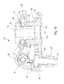
- a mounting part 3 which is mounted by means of screw 4 on a gate, not shown, a door, in particular a sectional door in the lower part of the last section, reproduced.
- a securing device 1, 40 recognizable, which is connected to a pull rope 5, which is guided over a deflection 11.
- the deflection 11 is connected on a common axis 12 with an externally mounted roller 2.
- the lower part with the deflection 11 forms a cover 13th
- the securing device 1, 40 essentially consists of a base part 9 which has a recess 21 and is fastened to the mounting part 3 via the main element 15 in connection with the nut 20. Through the recess 21 ensures that, for example, entered water does not remain in the security device and thus can flow.
- An upper part 7 of the securing device 1, 40 is connected to the base part 9 via an axis of rotation 8.
- the opening 34 is preferably applied oval and has to its interior projecting driver 35.
- These lateral drivers 35 preferably have the shape of a circular arc section or the like, wherein the connecting element 16 is supported on the upper rounding.
- the connecting element 16 is visible.
- the adjusting screw 6 which is secured by the lock nut 14.
- the traction cable 5 is connected.
- a round through hole 32 is present, which is penetrated by the connecting element 16.
- the connecting element 16 is designed as a circular component with a guide portion 33 and has in the upper part on its periphery a circumferential recess 26. In this recess 26 engage according to the Fig. 8 already described driver 35 and a spring element 28 and allow it so that the connecting element 16 is quasi floating embedded within the upper part 7 and upon pivoting of the upper part 7 about the pivot point 8, the connecting element 16 by the force of the spring element 28 its relative position change.
- a bore 19 for the connection to the adjusting screw 6 is present within the connecting element 16.
- an unillustrated thread within the bore 19 may be present.
- the securing device 1 is equipped with a spring element 28, which makes it possible to change the position of the upper part 7 relative to the base part 9 when the pulling cable 5 tears.
- the spring element 18 nestles or is supported on the one hand about the base part 9 and the other spring element end 27 is embedded within the recess 26 of the connecting element 16.
- a change in the position of the connecting element 16 is automatically effected with a response of the securing device 1.
- the driver 35 the upper part 7 is pivoted by the connecting element 16 about the pivot point.
- This change in position of the upper part 7 has the consequence that a sensor or switching element 29 via an actuating edge 31 or the like, in this case using a switching lug 30, is actuated.
- the sensor or switching element 29 is electrically connected to the motor circuit or the like so that when a response of the sensor or switching element 29, an immediate shutdown of the motor drive is effected.
- Fig. 6 From the Fig. 6 can be clearly seen the change in position of the upper part 7 to the base part 9. It is clear that the connecting element 16 has changed its relative position to the base part 9 by means of the spring element 28. From this representation of Fig. 6 can also be the response of the sensor or switching element 29 via the operating edge 31 and the switching flag 30 are removed. At the same time, a stop 24, which limits the pivotal movement of the upper part 7 relative to the base part 9, on the upper part 7.
- Fig. 7 which makes the securing device 1 visible from its underside, can be taken in particular the continuous recess 21, is caused by the drainage of water entered.
- FIG. 9 Another preferred embodiment of a securing device 40 is known.
- the connecting element 16 is not loaded by the spring element 28.
- the connecting element 16 is floating on the drivers 35.
- the spring element 28 is supported with its ends 27 on the base part 9 and against the upper part 7.
- the connecting element 16 has below its upper edge a circumferential groove, which in the illustrated Fig. 9 with a half-bore 36 within the base part 7 corresponds.
- the half-bore 36 is aligned with a holding surface 42 of the upper part 7.
- a securing element 49 is pushed through the half-bore 36 in order to hold the securing device 40 together against the spring force in order to facilitate the assembly ( Fig. 13 ).
- the securing element 49 In the presentation of the Fig. 11 can by the absence of the connecting element 16, the region of the driver 35 and the connection path for the securing element 49 visible.
- the securing element 49 passes through a bore 43 of the base part 9 and thus aligned retaining surfaces 42 in the upper part 7. If after mounting the securing element 49 is no longer needed, it can be inserted into a parking hole 48.
- the fuse element 49 can also be used for testing purposes of the sensor or switching element 29 via an opening 38.
- the spring element 28 used within the securing device 1, 40 can in a single representation of Fig. 12 be considered closer.
- a winding 44 with a receiving area 45 for the axis of rotation 8 two spring arms 46 which are spread apart in the rest position are present which end in regions 47 bent against one another in the spring element ends 27.
Landscapes
- Engineering & Computer Science (AREA)
- Structural Engineering (AREA)
- Architecture (AREA)
- Civil Engineering (AREA)
- Mechanical Engineering (AREA)
- Power-Operated Mechanisms For Wings (AREA)
- Gates (AREA)
Priority Applications (1)
| Application Number | Priority Date | Filing Date | Title |
|---|---|---|---|
| PL12164707T PL2514896T3 (pl) | 2011-04-20 | 2012-04-19 | Urządzenie zabezpieczające |
Applications Claiming Priority (1)
| Application Number | Priority Date | Filing Date | Title |
|---|---|---|---|
| DE202011000948U DE202011000948U1 (de) | 2011-04-20 | 2011-04-20 | Sicherungsvorrichtung |
Publications (3)
| Publication Number | Publication Date |
|---|---|
| EP2514896A2 true EP2514896A2 (fr) | 2012-10-24 |
| EP2514896A3 EP2514896A3 (fr) | 2014-12-17 |
| EP2514896B1 EP2514896B1 (fr) | 2018-11-28 |
Family
ID=44317500
Family Applications (1)
| Application Number | Title | Priority Date | Filing Date |
|---|---|---|---|
| EP12164707.7A Active EP2514896B1 (fr) | 2011-04-20 | 2012-04-19 | Dispositif de sécurisation |
Country Status (5)
| Country | Link |
|---|---|
| EP (1) | EP2514896B1 (fr) |
| DE (1) | DE202011000948U1 (fr) |
| DK (1) | DK2514896T3 (fr) |
| ES (1) | ES2713093T3 (fr) |
| PL (1) | PL2514896T3 (fr) |
Cited By (3)
| Publication number | Priority date | Publication date | Assignee | Title |
|---|---|---|---|---|
| DE102018103745A1 (de) | 2018-02-20 | 2019-08-22 | Fraba B.V. | Schlaffseilsicherungsanordnung für ein Antriebszugmittel |
| EP3819452A1 (fr) * | 2019-11-08 | 2021-05-12 | Alpha Deuren International BV | Portail |
| WO2022200500A1 (fr) * | 2021-03-25 | 2022-09-29 | Assa Abloy Entrance Systems Ab | Agencement de surveillance dans une porte sectionnelle basculante |
Families Citing this family (3)
| Publication number | Priority date | Publication date | Assignee | Title |
|---|---|---|---|---|
| DE102020104577B3 (de) * | 2020-02-21 | 2021-01-21 | Alpha Deuren International Bv | Elektrisches Schaltelement |
| DE202024106394U1 (de) | 2024-11-08 | 2024-12-23 | Alcomex Beheer Bv | Tragseilüberwachungseinheit für ein Torblatt |
| DE202024106393U1 (de) | 2024-11-08 | 2024-12-06 | Alcomex Beheer Bv | Tragseilüberwachungseinheit für ein Torblatt |
Citations (2)
| Publication number | Priority date | Publication date | Assignee | Title |
|---|---|---|---|---|
| DE7912249U1 (de) | 1979-04-26 | 1979-09-06 | Tuerenwerke Riexinger Gmbh & Co Kg, 7129 Brackenheim | Seilzug mit toraufhaenger und darin eingebauter schlaffseilsicherung fuer ein deckenglieder- oder rolltor |
| DE10113847A1 (de) | 2001-03-21 | 2002-09-26 | Hoermann Kg | Sicherungsvorrichtung |
Family Cites Families (4)
| Publication number | Priority date | Publication date | Assignee | Title |
|---|---|---|---|---|
| DE29503553U1 (de) * | 1995-01-05 | 1996-05-09 | MARANTEC Antriebs- und Steuerungstechnik GmbH & Co. Produktions-KG, 33428 Marienfeld | Überwachungseinrichtung für ein Tragseil eines Torblattes |
| CA2263666A1 (fr) * | 1999-03-18 | 2000-09-18 | Pierre-Louis Foucault | Dispositif de protection contre les bris de cables |
| DE20204194U1 (de) * | 2002-03-15 | 2003-07-24 | Marantec Antriebs- und Steuerungstechnik GmbH & Co. KG, 33428 Marienfeld | Sicherheitsschaltereinrichtung zum Schalten eines Torantriebes |
| NL1030916C2 (nl) * | 2006-01-13 | 2007-07-17 | Flexi Force B V | Kabelbreukbeveiligingsmechanisme. |
-
2011
- 2011-04-20 DE DE202011000948U patent/DE202011000948U1/de not_active Expired - Lifetime
-
2012
- 2012-04-19 PL PL12164707T patent/PL2514896T3/pl unknown
- 2012-04-19 EP EP12164707.7A patent/EP2514896B1/fr active Active
- 2012-04-19 DK DK12164707.7T patent/DK2514896T3/en active
- 2012-04-19 ES ES12164707T patent/ES2713093T3/es active Active
Patent Citations (2)
| Publication number | Priority date | Publication date | Assignee | Title |
|---|---|---|---|---|
| DE7912249U1 (de) | 1979-04-26 | 1979-09-06 | Tuerenwerke Riexinger Gmbh & Co Kg, 7129 Brackenheim | Seilzug mit toraufhaenger und darin eingebauter schlaffseilsicherung fuer ein deckenglieder- oder rolltor |
| DE10113847A1 (de) | 2001-03-21 | 2002-09-26 | Hoermann Kg | Sicherungsvorrichtung |
Cited By (5)
| Publication number | Priority date | Publication date | Assignee | Title |
|---|---|---|---|---|
| DE102018103745A1 (de) | 2018-02-20 | 2019-08-22 | Fraba B.V. | Schlaffseilsicherungsanordnung für ein Antriebszugmittel |
| DE102018103745B4 (de) | 2018-02-20 | 2024-09-26 | Cedes Ag | Schlaffseilsicherungsanordnung für ein Antriebszugmittel |
| EP3819452A1 (fr) * | 2019-11-08 | 2021-05-12 | Alpha Deuren International BV | Portail |
| DE102019130229A1 (de) * | 2019-11-08 | 2021-05-12 | Alpha Deuren International Bv | Tor |
| WO2022200500A1 (fr) * | 2021-03-25 | 2022-09-29 | Assa Abloy Entrance Systems Ab | Agencement de surveillance dans une porte sectionnelle basculante |
Also Published As
| Publication number | Publication date |
|---|---|
| ES2713093T3 (es) | 2019-05-17 |
| DE202011000948U1 (de) | 2011-06-28 |
| EP2514896B1 (fr) | 2018-11-28 |
| EP2514896A3 (fr) | 2014-12-17 |
| DK2514896T3 (en) | 2019-03-11 |
| PL2514896T3 (pl) | 2019-05-31 |
Similar Documents
| Publication | Publication Date | Title |
|---|---|---|
| EP2514896B1 (fr) | Dispositif de sécurisation | |
| DE102012014696B4 (de) | Dachträger für ein Kraftfahrzeug, Verfahren zum Betreiben eines Steuergeräts eines Kraftfahrzeugs sowie entsprechendes Steuergerät | |
| DE2917797C2 (de) | Einklemmsicherung für selbsttätig öffnende und schließende Türen | |
| DE102007017916B3 (de) | Scharnieranordnung | |
| DE102015208441B3 (de) | Beschattungsvorrichtung für eine Scheibe eines Kraftfahrzeugs | |
| EP2634785A1 (fr) | Dispositif de commutation | |
| DE102017209719A1 (de) | Fensterheberbaugruppe mit Sicherungselement und Sicherungsabschnitt für die Sicherung eines Zugmittels | |
| EP3667010B1 (fr) | Dispositif de butée pour un joint de porte automatique, en particulier pour une porte pivotante ou battante, agencement d'un joint de porte automatique et d'un dispositif de butée | |
| DE102009039623B4 (de) | Torantriebsvorrichtung mit Zugmittelüberwachungseinrichtung sowie damit versehenes Tor | |
| EP0195102A1 (fr) | Contacteur électrique pour la surveillance d'une vis vissée dans un filetage ou un matériel élastique | |
| DE19949186A1 (de) | Türscharnier | |
| EP3166373B1 (fr) | Module de serrage destine a etre fixe sur un rail support | |
| DE102007039549A1 (de) | Verschlusseinrichtung und Tor, Tür oder dergleichen mit einer solchen Verschlusseinrichtung | |
| EP3870788B1 (fr) | Système de lève-vitre et portière de véhicule automobile | |
| DE102018108217A1 (de) | Endlagenspeichervorrichtung sowie ein Tor mit einer Endlagenspeichervorrichtung | |
| DE102009043395A1 (de) | Stabilisator für den unteren Anschlag eines Fensterglases bei einer Fahrzeugtür | |
| EP1972747B1 (fr) | Commande de portail automatique | |
| EP3163007B1 (fr) | Dispositif de déclenchement de fin de course d'un entraînement motorisé d'un arbre d'enroulement d'un volet roulant | |
| EP1353105B1 (fr) | Attache de fixation pour câbles | |
| DE7917854U1 (de) | Torantrieb mit einem elektrischen antriebsmotoraggregat | |
| DE4100608A1 (de) | Antriebsvorrichtung fuer eine rollflaeche | |
| DE2917023A1 (de) | Seilzug mit toraufhaenger und darin eingebauter schlaffseilsicherung fuer ein deckenglieder- oder rolltor | |
| EP0928508B1 (fr) | Dispositif de verrouillage contre l'actionnement de l'organe de translation d'un disjoncteur | |
| DE102017012254A1 (de) | Fensterheberbaugruppe mit Sicherungseiement und Sicherungsabschnitt für die Sicherung eines Zugmittels | |
| EP0258639B1 (fr) | Palier rotatif avec dispositif de freinage pour un panneau de fenêtre, porte ou similaire |
Legal Events
| Date | Code | Title | Description |
|---|---|---|---|
| PUAI | Public reference made under article 153(3) epc to a published international application that has entered the european phase |
Free format text: ORIGINAL CODE: 0009012 |
|
| AK | Designated contracting states |
Kind code of ref document: A2 Designated state(s): AL AT BE BG CH CY CZ DE DK EE ES FI FR GB GR HR HU IE IS IT LI LT LU LV MC MK MT NL NO PL PT RO RS SE SI SK SM TR |
|
| AX | Request for extension of the european patent |
Extension state: BA ME |
|
| PUAL | Search report despatched |
Free format text: ORIGINAL CODE: 0009013 |
|
| AK | Designated contracting states |
Kind code of ref document: A3 Designated state(s): AL AT BE BG CH CY CZ DE DK EE ES FI FR GB GR HR HU IE IS IT LI LT LU LV MC MK MT NL NO PL PT RO RS SE SI SK SM TR |
|
| AX | Request for extension of the european patent |
Extension state: BA ME |
|
| RIC1 | Information provided on ipc code assigned before grant |
Ipc: E05D 13/00 20060101AFI20141107BHEP Ipc: E05F 15/18 20060101ALN20141107BHEP Ipc: E05F 15/00 20060101ALN20141107BHEP |
|
| 17P | Request for examination filed |
Effective date: 20150616 |
|
| RBV | Designated contracting states (corrected) |
Designated state(s): AL AT BE BG CH CY CZ DE DK EE ES FI FR GB GR HR HU IE IS IT LI LT LU LV MC MK MT NL NO PL PT RO RS SE SI SK SM TR |
|
| 17Q | First examination report despatched |
Effective date: 20160915 |
|
| STAA | Information on the status of an ep patent application or granted ep patent |
Free format text: STATUS: EXAMINATION IS IN PROGRESS |
|
| GRAP | Despatch of communication of intention to grant a patent |
Free format text: ORIGINAL CODE: EPIDOSNIGR1 |
|
| STAA | Information on the status of an ep patent application or granted ep patent |
Free format text: STATUS: GRANT OF PATENT IS INTENDED |
|
| RIC1 | Information provided on ipc code assigned before grant |
Ipc: E05F 15/00 20060101ALN20180619BHEP Ipc: E05D 13/00 20060101AFI20180619BHEP Ipc: E05F 15/41 20150101ALN20180619BHEP |
|
| INTG | Intention to grant announced |
Effective date: 20180720 |
|
| GRAS | Grant fee paid |
Free format text: ORIGINAL CODE: EPIDOSNIGR3 |
|
| GRAA | (expected) grant |
Free format text: ORIGINAL CODE: 0009210 |
|
| STAA | Information on the status of an ep patent application or granted ep patent |
Free format text: STATUS: THE PATENT HAS BEEN GRANTED |
|
| AK | Designated contracting states |
Kind code of ref document: B1 Designated state(s): AL AT BE BG CH CY CZ DE DK EE ES FI FR GB GR HR HU IE IS IT LI LT LU LV MC MK MT NL NO PL PT RO RS SE SI SK SM TR |
|
| REG | Reference to a national code |
Ref country code: GB Ref legal event code: FG4D Free format text: NOT ENGLISH |
|
| REG | Reference to a national code |
Ref country code: CH Ref legal event code: EP |
|
| REG | Reference to a national code |
Ref country code: AT Ref legal event code: REF Ref document number: 1070436 Country of ref document: AT Kind code of ref document: T Effective date: 20181215 |
|
| REG | Reference to a national code |
Ref country code: DE Ref legal event code: R096 Ref document number: 502012013895 Country of ref document: DE |
|
| REG | Reference to a national code |
Ref country code: IE Ref legal event code: FG4D Free format text: LANGUAGE OF EP DOCUMENT: GERMAN |
|
| REG | Reference to a national code |
Ref country code: DK Ref legal event code: T3 Effective date: 20190304 |
|
| REG | Reference to a national code |
Ref country code: SE Ref legal event code: TRGR |
|
| REG | Reference to a national code |
Ref country code: NL Ref legal event code: FP |
|
| REG | Reference to a national code |
Ref country code: LT Ref legal event code: MG4D |
|
| PG25 | Lapsed in a contracting state [announced via postgrant information from national office to epo] |
Ref country code: IS Free format text: LAPSE BECAUSE OF FAILURE TO SUBMIT A TRANSLATION OF THE DESCRIPTION OR TO PAY THE FEE WITHIN THE PRESCRIBED TIME-LIMIT Effective date: 20190328 Ref country code: NO Free format text: LAPSE BECAUSE OF FAILURE TO SUBMIT A TRANSLATION OF THE DESCRIPTION OR TO PAY THE FEE WITHIN THE PRESCRIBED TIME-LIMIT Effective date: 20190228 Ref country code: LT Free format text: LAPSE BECAUSE OF FAILURE TO SUBMIT A TRANSLATION OF THE DESCRIPTION OR TO PAY THE FEE WITHIN THE PRESCRIBED TIME-LIMIT Effective date: 20181128 Ref country code: BG Free format text: LAPSE BECAUSE OF FAILURE TO SUBMIT A TRANSLATION OF THE DESCRIPTION OR TO PAY THE FEE WITHIN THE PRESCRIBED TIME-LIMIT Effective date: 20190228 Ref country code: HR Free format text: LAPSE BECAUSE OF FAILURE TO SUBMIT A TRANSLATION OF THE DESCRIPTION OR TO PAY THE FEE WITHIN THE PRESCRIBED TIME-LIMIT Effective date: 20181128 Ref country code: LV Free format text: LAPSE BECAUSE OF FAILURE TO SUBMIT A TRANSLATION OF THE DESCRIPTION OR TO PAY THE FEE WITHIN THE PRESCRIBED TIME-LIMIT Effective date: 20181128 Ref country code: FI Free format text: LAPSE BECAUSE OF FAILURE TO SUBMIT A TRANSLATION OF THE DESCRIPTION OR TO PAY THE FEE WITHIN THE PRESCRIBED TIME-LIMIT Effective date: 20181128 |
|
| REG | Reference to a national code |
Ref country code: ES Ref legal event code: FG2A Ref document number: 2713093 Country of ref document: ES Kind code of ref document: T3 Effective date: 20190517 |
|
| PG25 | Lapsed in a contracting state [announced via postgrant information from national office to epo] |
Ref country code: RS Free format text: LAPSE BECAUSE OF FAILURE TO SUBMIT A TRANSLATION OF THE DESCRIPTION OR TO PAY THE FEE WITHIN THE PRESCRIBED TIME-LIMIT Effective date: 20181128 Ref country code: AL Free format text: LAPSE BECAUSE OF FAILURE TO SUBMIT A TRANSLATION OF THE DESCRIPTION OR TO PAY THE FEE WITHIN THE PRESCRIBED TIME-LIMIT Effective date: 20181128 Ref country code: GR Free format text: LAPSE BECAUSE OF FAILURE TO SUBMIT A TRANSLATION OF THE DESCRIPTION OR TO PAY THE FEE WITHIN THE PRESCRIBED TIME-LIMIT Effective date: 20190301 Ref country code: PT Free format text: LAPSE BECAUSE OF FAILURE TO SUBMIT A TRANSLATION OF THE DESCRIPTION OR TO PAY THE FEE WITHIN THE PRESCRIBED TIME-LIMIT Effective date: 20190328 |
|
| PG25 | Lapsed in a contracting state [announced via postgrant information from national office to epo] |
Ref country code: IT Free format text: LAPSE BECAUSE OF FAILURE TO SUBMIT A TRANSLATION OF THE DESCRIPTION OR TO PAY THE FEE WITHIN THE PRESCRIBED TIME-LIMIT Effective date: 20181128 Ref country code: CZ Free format text: LAPSE BECAUSE OF FAILURE TO SUBMIT A TRANSLATION OF THE DESCRIPTION OR TO PAY THE FEE WITHIN THE PRESCRIBED TIME-LIMIT Effective date: 20181128 |
|
| REG | Reference to a national code |
Ref country code: DE Ref legal event code: R097 Ref document number: 502012013895 Country of ref document: DE |
|
| PG25 | Lapsed in a contracting state [announced via postgrant information from national office to epo] |
Ref country code: SM Free format text: LAPSE BECAUSE OF FAILURE TO SUBMIT A TRANSLATION OF THE DESCRIPTION OR TO PAY THE FEE WITHIN THE PRESCRIBED TIME-LIMIT Effective date: 20181128 Ref country code: SK Free format text: LAPSE BECAUSE OF FAILURE TO SUBMIT A TRANSLATION OF THE DESCRIPTION OR TO PAY THE FEE WITHIN THE PRESCRIBED TIME-LIMIT Effective date: 20181128 Ref country code: EE Free format text: LAPSE BECAUSE OF FAILURE TO SUBMIT A TRANSLATION OF THE DESCRIPTION OR TO PAY THE FEE WITHIN THE PRESCRIBED TIME-LIMIT Effective date: 20181128 Ref country code: RO Free format text: LAPSE BECAUSE OF FAILURE TO SUBMIT A TRANSLATION OF THE DESCRIPTION OR TO PAY THE FEE WITHIN THE PRESCRIBED TIME-LIMIT Effective date: 20181128 |
|
| PLBE | No opposition filed within time limit |
Free format text: ORIGINAL CODE: 0009261 |
|
| STAA | Information on the status of an ep patent application or granted ep patent |
Free format text: STATUS: NO OPPOSITION FILED WITHIN TIME LIMIT |
|
| PG25 | Lapsed in a contracting state [announced via postgrant information from national office to epo] |
Ref country code: SI Free format text: LAPSE BECAUSE OF FAILURE TO SUBMIT A TRANSLATION OF THE DESCRIPTION OR TO PAY THE FEE WITHIN THE PRESCRIBED TIME-LIMIT Effective date: 20181128 |
|
| 26N | No opposition filed |
Effective date: 20190829 |
|
| REG | Reference to a national code |
Ref country code: CH Ref legal event code: PL |
|
| PG25 | Lapsed in a contracting state [announced via postgrant information from national office to epo] |
Ref country code: LU Free format text: LAPSE BECAUSE OF NON-PAYMENT OF DUE FEES Effective date: 20190419 Ref country code: MC Free format text: LAPSE BECAUSE OF FAILURE TO SUBMIT A TRANSLATION OF THE DESCRIPTION OR TO PAY THE FEE WITHIN THE PRESCRIBED TIME-LIMIT Effective date: 20181128 |
|
| PG25 | Lapsed in a contracting state [announced via postgrant information from national office to epo] |
Ref country code: LI Free format text: LAPSE BECAUSE OF NON-PAYMENT OF DUE FEES Effective date: 20190430 Ref country code: CH Free format text: LAPSE BECAUSE OF NON-PAYMENT OF DUE FEES Effective date: 20190430 |
|
| PG25 | Lapsed in a contracting state [announced via postgrant information from national office to epo] |
Ref country code: TR Free format text: LAPSE BECAUSE OF FAILURE TO SUBMIT A TRANSLATION OF THE DESCRIPTION OR TO PAY THE FEE WITHIN THE PRESCRIBED TIME-LIMIT Effective date: 20181128 |
|
| PG25 | Lapsed in a contracting state [announced via postgrant information from national office to epo] |
Ref country code: IE Free format text: LAPSE BECAUSE OF NON-PAYMENT OF DUE FEES Effective date: 20190419 |
|
| REG | Reference to a national code |
Ref country code: AT Ref legal event code: MM01 Ref document number: 1070436 Country of ref document: AT Kind code of ref document: T Effective date: 20190419 |
|
| PG25 | Lapsed in a contracting state [announced via postgrant information from national office to epo] |
Ref country code: AT Free format text: LAPSE BECAUSE OF NON-PAYMENT OF DUE FEES Effective date: 20190419 |
|
| PG25 | Lapsed in a contracting state [announced via postgrant information from national office to epo] |
Ref country code: CY Free format text: LAPSE BECAUSE OF FAILURE TO SUBMIT A TRANSLATION OF THE DESCRIPTION OR TO PAY THE FEE WITHIN THE PRESCRIBED TIME-LIMIT Effective date: 20181128 |
|
| PG25 | Lapsed in a contracting state [announced via postgrant information from national office to epo] |
Ref country code: MT Free format text: LAPSE BECAUSE OF FAILURE TO SUBMIT A TRANSLATION OF THE DESCRIPTION OR TO PAY THE FEE WITHIN THE PRESCRIBED TIME-LIMIT Effective date: 20181128 Ref country code: HU Free format text: LAPSE BECAUSE OF FAILURE TO SUBMIT A TRANSLATION OF THE DESCRIPTION OR TO PAY THE FEE WITHIN THE PRESCRIBED TIME-LIMIT; INVALID AB INITIO Effective date: 20120419 |
|
| PG25 | Lapsed in a contracting state [announced via postgrant information from national office to epo] |
Ref country code: MK Free format text: LAPSE BECAUSE OF FAILURE TO SUBMIT A TRANSLATION OF THE DESCRIPTION OR TO PAY THE FEE WITHIN THE PRESCRIBED TIME-LIMIT Effective date: 20181128 |
|
| PGFP | Annual fee paid to national office [announced via postgrant information from national office to epo] |
Ref country code: NL Payment date: 20250418 Year of fee payment: 14 |
|
| PGFP | Annual fee paid to national office [announced via postgrant information from national office to epo] |
Ref country code: PL Payment date: 20250410 Year of fee payment: 14 Ref country code: DE Payment date: 20250422 Year of fee payment: 14 |
|
| PGFP | Annual fee paid to national office [announced via postgrant information from national office to epo] |
Ref country code: GB Payment date: 20250423 Year of fee payment: 14 Ref country code: ES Payment date: 20250529 Year of fee payment: 14 Ref country code: DK Payment date: 20250429 Year of fee payment: 14 |
|
| PGFP | Annual fee paid to national office [announced via postgrant information from national office to epo] |
Ref country code: BE Payment date: 20250418 Year of fee payment: 14 |
|
| PGFP | Annual fee paid to national office [announced via postgrant information from national office to epo] |
Ref country code: FR Payment date: 20250425 Year of fee payment: 14 |
|
| PGFP | Annual fee paid to national office [announced via postgrant information from national office to epo] |
Ref country code: SE Payment date: 20250429 Year of fee payment: 14 |