EP2514896B1 - Sicherungsvorrichtung - Google Patents
Sicherungsvorrichtung Download PDFInfo
- Publication number
- EP2514896B1 EP2514896B1 EP12164707.7A EP12164707A EP2514896B1 EP 2514896 B1 EP2514896 B1 EP 2514896B1 EP 12164707 A EP12164707 A EP 12164707A EP 2514896 B1 EP2514896 B1 EP 2514896B1
- Authority
- EP
- European Patent Office
- Prior art keywords
- securing device
- connecting element
- door
- cable
- door leaf
- Prior art date
- Legal status (The legal status is an assumption and is not a legal conclusion. Google has not performed a legal analysis and makes no representation as to the accuracy of the status listed.)
- Active
Links
Images






Classifications
-
- E—FIXED CONSTRUCTIONS
- E05—LOCKS; KEYS; WINDOW OR DOOR FITTINGS; SAFES
- E05D—HINGES OR SUSPENSION DEVICES FOR DOORS, WINDOWS OR WINGS
- E05D13/00—Accessories for sliding or lifting wings, e.g. pulleys, safety catches
- E05D13/003—Anti-dropping devices
- E05D13/006—Anti-dropping devices fixed to the wing, i.e. safety catches
-
- E—FIXED CONSTRUCTIONS
- E05—LOCKS; KEYS; WINDOW OR DOOR FITTINGS; SAFES
- E05F—DEVICES FOR MOVING WINGS INTO OPEN OR CLOSED POSITION; CHECKS FOR WINGS; WING FITTINGS NOT OTHERWISE PROVIDED FOR, CONCERNED WITH THE FUNCTIONING OF THE WING
- E05F15/00—Power-operated mechanisms for wings
- E05F15/40—Safety devices, e.g. detection of obstructions or end positions
- E05F15/41—Detection by monitoring transmitted force or torque; Safety couplings with activation dependent upon torque or force, e.g. slip couplings
-
- E—FIXED CONSTRUCTIONS
- E05—LOCKS; KEYS; WINDOW OR DOOR FITTINGS; SAFES
- E05F—DEVICES FOR MOVING WINGS INTO OPEN OR CLOSED POSITION; CHECKS FOR WINGS; WING FITTINGS NOT OTHERWISE PROVIDED FOR, CONCERNED WITH THE FUNCTIONING OF THE WING
- E05F15/00—Power-operated mechanisms for wings
- E05F15/60—Power-operated mechanisms for wings using electrical actuators
-
- E—FIXED CONSTRUCTIONS
- E05—LOCKS; KEYS; WINDOW OR DOOR FITTINGS; SAFES
- E05F—DEVICES FOR MOVING WINGS INTO OPEN OR CLOSED POSITION; CHECKS FOR WINGS; WING FITTINGS NOT OTHERWISE PROVIDED FOR, CONCERNED WITH THE FUNCTIONING OF THE WING
- E05F15/00—Power-operated mechanisms for wings
- E05F15/60—Power-operated mechanisms for wings using electrical actuators
- E05F15/603—Power-operated mechanisms for wings using electrical actuators using rotary electromotors
- E05F15/665—Power-operated mechanisms for wings using electrical actuators using rotary electromotors for vertically-sliding wings
- E05F15/668—Power-operated mechanisms for wings using electrical actuators using rotary electromotors for vertically-sliding wings for overhead wings
- E05F15/681—Power-operated mechanisms for wings using electrical actuators using rotary electromotors for vertically-sliding wings for overhead wings operated by flexible elongated pulling elements, e.g. belts
- E05F15/686—Power-operated mechanisms for wings using electrical actuators using rotary electromotors for vertically-sliding wings for overhead wings operated by flexible elongated pulling elements, e.g. belts by cables or ropes
-
- E—FIXED CONSTRUCTIONS
- E06—DOORS, WINDOWS, SHUTTERS, OR ROLLER BLINDS IN GENERAL; LADDERS
- E06B—FIXED OR MOVABLE CLOSURES FOR OPENINGS IN BUILDINGS, VEHICLES, FENCES OR LIKE ENCLOSURES IN GENERAL, e.g. DOORS, WINDOWS, BLINDS, GATES
- E06B9/00—Screening or protective devices for wall or similar openings, with or without operating or securing mechanisms; Closures of similar construction
- E06B9/56—Operating, guiding or securing devices or arrangements for roll-type closures; Spring drums; Tape drums; Counterweighting arrangements therefor
- E06B9/80—Safety measures against dropping or unauthorised opening; Braking or immobilising devices; Devices for limiting unrolling
- E06B9/82—Safety measures against dropping or unauthorised opening; Braking or immobilising devices; Devices for limiting unrolling automatic
- E06B9/84—Safety measures against dropping or unauthorised opening; Braking or immobilising devices; Devices for limiting unrolling automatic against dropping
-
- E—FIXED CONSTRUCTIONS
- E05—LOCKS; KEYS; WINDOW OR DOOR FITTINGS; SAFES
- E05Y—INDEXING SCHEME ASSOCIATED WITH SUBCLASSES E05D AND E05F, RELATING TO CONSTRUCTION ELEMENTS, ELECTRIC CONTROL, POWER SUPPLY, POWER SIGNAL OR TRANSMISSION, USER INTERFACES, MOUNTING OR COUPLING, DETAILS, ACCESSORIES, AUXILIARY OPERATIONS NOT OTHERWISE PROVIDED FOR, APPLICATION THEREOF
- E05Y2600/00—Mounting or coupling arrangements for elements provided for in this subclass
- E05Y2600/10—Adjustable
-
- E—FIXED CONSTRUCTIONS
- E05—LOCKS; KEYS; WINDOW OR DOOR FITTINGS; SAFES
- E05Y—INDEXING SCHEME ASSOCIATED WITH SUBCLASSES E05D AND E05F, RELATING TO CONSTRUCTION ELEMENTS, ELECTRIC CONTROL, POWER SUPPLY, POWER SIGNAL OR TRANSMISSION, USER INTERFACES, MOUNTING OR COUPLING, DETAILS, ACCESSORIES, AUXILIARY OPERATIONS NOT OTHERWISE PROVIDED FOR, APPLICATION THEREOF
- E05Y2800/00—Details, accessories and auxiliary operations not otherwise provided for
- E05Y2800/40—Physical or chemical protection
- E05Y2800/424—Physical or chemical protection against unintended use, e.g. protection against vandalism or sabotage
-
- E—FIXED CONSTRUCTIONS
- E05—LOCKS; KEYS; WINDOW OR DOOR FITTINGS; SAFES
- E05Y—INDEXING SCHEME ASSOCIATED WITH SUBCLASSES E05D AND E05F, RELATING TO CONSTRUCTION ELEMENTS, ELECTRIC CONTROL, POWER SUPPLY, POWER SIGNAL OR TRANSMISSION, USER INTERFACES, MOUNTING OR COUPLING, DETAILS, ACCESSORIES, AUXILIARY OPERATIONS NOT OTHERWISE PROVIDED FOR, APPLICATION THEREOF
- E05Y2900/00—Application of doors, windows, wings or fittings thereof
-
- E—FIXED CONSTRUCTIONS
- E05—LOCKS; KEYS; WINDOW OR DOOR FITTINGS; SAFES
- E05Y—INDEXING SCHEME ASSOCIATED WITH SUBCLASSES E05D AND E05F, RELATING TO CONSTRUCTION ELEMENTS, ELECTRIC CONTROL, POWER SUPPLY, POWER SIGNAL OR TRANSMISSION, USER INTERFACES, MOUNTING OR COUPLING, DETAILS, ACCESSORIES, AUXILIARY OPERATIONS NOT OTHERWISE PROVIDED FOR, APPLICATION THEREOF
- E05Y2900/00—Application of doors, windows, wings or fittings thereof
- E05Y2900/10—Application of doors, windows, wings or fittings thereof for buildings or parts thereof
- E05Y2900/106—Application of doors, windows, wings or fittings thereof for buildings or parts thereof for garages
Definitions
- the invention relates to a securing device for a portable door leaf of a gate, in particular a sectional door, which is moved between an open position and a closed position via guide rails.
- the door leaf is laterally equipped with pull ropes, which are fixed in the lower part of the door leaf and guided over deflections. These can also work together with a spring device.
- Such a goal is for example from the DE 79 12 249 U1 known.
- the gate hanger has a fastening device for the pull cable next to a switch for switching off the cable pull motor and an actuating part for the switch.
- the DE 101 13 847 discloses a securing device for a, along a predetermined path between an preferably overhead arranged open position and a closed position movable door leaf with at least one between a release position in which it releases the door movement and a securing position in which it counteracts possibly cooperating with other security elements of a Torblattêt , adjustable fuse element.
- the invention is characterized in that the adjusted in the securing position securing element counteracts at least along a first, merging into the open position portion of the predetermined path, optionally cooperating with at least one further securing element closing movement of the door leaf from the open position to the closed position and in the Closed position and / or along a transition into the closed position second portion of the predetermined path, optionally cooperating with at least one further securing element, counteracts an opening movement of a door leaf from the closed position into the open position.
- a control cam for actuating a switch of a drive device for the Door leaf at a pivoting of the safety lever from the release position into the securing position available.
- traction ropes are usually mounted laterally in the lower region of the gates, so that the overhead sectional door or roller shutter door can be brought into the open position via cable drums, in conjunction with a drive motor at an opening by pulling on the ropes.
- the drive operates in the opposite direction. It is of great importance that, for example, with a rupture of such tension cables, there is a tilting of the individual sectors within the lateral guide rails. The same would apply if, for example, in case of failure of safety devices or other events, for example, the door leaf is driving on an obstacle.
- slack rope fuses the task of which is to cause a rupture of the drive motor directly when tearing or running onto an obstacle of such a traction cable.
- the monitoring device consists of an electric catching device, which is connected in the carrying cable and connected to a drive motor, which is used for the movement of the door leaf.
- the electric catching device By the electric catching device, the drive motor is automatically disconnected in a cable break.
- a mechanical safety device for the door leaf is present.
- the DE 202 04 194 U1 describes a safety switch device for switching a door drive with at least one support cable for a single or multi-part door leaf of a gate, which has a safety device with at least two pivotally interconnected around an axis main parts.
- a safety device with at least two pivotally interconnected around an axis main parts.
- main parts at least one has an approximately U-shaped frame, wherein a spring means for generating a bias between the two main parts about the axis, and a cable attachment, which connects the at least one support cable with the safety gear such that the two main parts in Normal operation of the door leaf are held by the tension of the at least one support cable against the bias of the spring device in a rest position to each other.
- the EP 1 808 563 A2 as well as the WO 00/570 11 A1 describe in a similar manner safety devices for supporting cables of gates.
- the object of the invention is to provide a securing device for a portable door leaf of a gate, in particular a sectional door, which is easy to install and set, can not be manipulated and is inexpensive to manufacture and replaceable.
- the object of the invention is solved by the features of claim 1.
- the dependent claims provide a further embodiment of the inventive concept again.
- the invention is characterized in that a securing device for a portable door leaf of a gate, in particular a sectional door, which is moved between an open position and a closed position on guide rails, is secured so that the side of the door leaf arranged pull ropes either either or only one an additional safety device to be acted upon.
- the safety device is designed so that when the door leaf is closed a stepless cable length adjustment is given.
- the securing device can be attached to a base part, which is located at the lower part of the door leaf or the last section of a sectional door, by a simple installation by means of a screw interchangeable.
- the securing device is secured against rotation at the same time.
- the securing device consists of the base part, which is completed by an upper part via an axis of rotation and cooperates with the upper part functionally on the axis of rotation.
- a connecting part is contained, which is guided within a bore of the base part.
- this connection part which may have a bore or a thread, the length of the cable is set and fixed by means of an adjusting screw and a cooperating lock nut.
- the upper part is also spring-loaded with respect to the base part, so that when the traction cable is not connected or when the traction cable is changed or torn, the upper part is at least partially lifted or pivoted away from the base part by the spring element, at least in its position.
- a sensor or a switching element which is located within the securing device is simultaneously detected by an actuating edge. This sensor or switching element engages directly or indirectly in the motor circuit, so that the motor function is stopped immediately when the sensor or switching element respond.
- such a spring design is selected, which is placed as a winding around the pivot point of the upper part and is supported with a spring end against the base part.
- the other end of the spring acts on the floating connection element.
- the connecting element is not loaded by the spring element.
- the connecting element By pulling the cable thus the connecting element is held against the upper part of the securing device.
- the second end of the spring is supported rather directly against the upper part.
- the mobility of the connecting element is even greater than in the first preferred embodiment and guarantees trouble-free door operation.
- Such versions of the securing device are easy to install and also interchangeable and require only a small space and are very accessible.
- the fact that the sensor or switching element is located below the upper part of the securing device, this is sufficiently protected against manipulation or damage. Such a sensor or switching element can be tested in the installed state for its functionality, without having to dismantle parts.
- a mounting part 3 which is mounted by means of screw 4 on a gate, not shown, a door, in particular a sectional door in the lower part of the last section, reproduced.
- a securing device 1, 40 From the Fig. 1 is in the upper part of a securing device 1, 40 can be seen, with a pull rope 5, which via a deflection 11th is connected.
- the deflection 11 is connected on a common axis 12 with an externally mounted roller 2.
- the part with the deflection 11 protects a cover 13th In the side view of Fig.
- the pull cable 5 is connected to the one securing device 1, 40, for example via an eyelet 25 and after leaving the deflection 11, the pull cable 5 goes to a driven winding shaft, not shown, to perform an actuation of the door leaf.
- a bore 23 is present.
- the securing device 1, 40 by means of a screw 15 with the mounting part 3 positively and positively connected.
- the Fig. 3 clearly a cable connection 10 of the traction cable 5.
- the securing device 1, 40 essentially consists of a base part 9, which has a recess 21 and is fastened to the mounting part 3 via the screw element 15 in conjunction with a nut 20. Through the recess 21 ensures that, for example, entered water does not remain in the security device and thus can flow.
- An upper part 7 of the securing device 1, 40 is connected to the base part 9 via an axis of rotation 8.
- the opening 34 is designed oval and has to its interior projecting driver 35.
- These lateral drivers 35 preferably have the shape of a circular arc section or the like, wherein a connecting element 16 is supported on the upper rounding.
- the connecting element 16 is visible.
- the adjusting screw 6 which is secured by the lock nut 14.
- About a length adjustment using the adjusting screw 6 is connected via the eyelet 25 and the cable connection 10, connected traction cable 5.
- a round through hole 32 is present, which is penetrated by the connecting element 16.
- the connecting element 16 is designed as a circular component with a guide portion 33 and has in the upper part on its periphery a circumferential recess 26. In this recess 26 engage according to the Fig.
- the connecting element 16 can change its relative position by the force of the spring element 28 , In the axial direction, a bore 19 for the connection to the adjusting screw 6 is present within the connecting element 16.
- a bore 19 for the connection to the adjusting screw 6 is present within the connecting element 16.
- an unillustrated thread within the bore 19 may be present.
- the securing device 1 is equipped with a spring element 28, which makes it possible to change the position of the upper part 7 relative to the base part 9 when the pulling cable 5 tears.
- the spring element 18 nestles or is supported on the one hand about the base part 9 and the other spring element end 27 is embedded within the recess 26 of the connecting element 16.
- a change in position of the connecting element 16 causes the axis of rotation 8 with a response of the securing device 1 automatically.
- the driver 35 By the driver 35, the upper part 7 is pivoted by the connecting element 16 about the pivot point.
- This change in position of the upper part 7 has the consequence that a sensor or switching element 29 via an actuating edge 31 or the like, in this case using a switching lug 30, is actuated.
- the sensor or switching element 29 is electrically connected to the motor circuit so that when a response of the sensor or switching element 29, an immediate shutdown of the motor drive is effected. From the Fig. 6 can be clearly seen the change in position of the upper part 7 to the base part 9.
- a further non-inventive embodiment of a securing device 40 is known.
- the connecting element 16 is not loaded by the spring element 28.
- the connecting element 16 is floating on the drivers 35.
- the spring element 28 is supported with its spring ends 27 on the base part 9 and against the upper part 7.
- the connecting element 16 has below its upper edge a circumferential groove which in the Fig. 9 with a half-bore 36 within the base part 7 corresponds.
- the half-bore 36 is aligned with a holding surface 42 of the upper part 7.
- a securing element 49 is pushed through the half-bore 36 to hold the securing device 40 against the spring force, and to facilitate the assembly ( Fig.
- the position of the securing device 40 with raised by the spring element 28 upper part 7 can Fig. 10 be removed. It is clear here also the lifting of the connecting element 16th In the presentation of the Fig. 11 can be visible by the absence of the connecting element 16 of the region of the driver 35 and the connection path for the fuse element 49.
- the securing element 49 passes through a bore 43 of the base part 9 and thus aligned holding surfaces 42 in the upper part 7. If after securing the securing element 49 is no longer needed, it can be plugged into a parking hole 48.
- the fuse element 49 can also be used for testing purposes of the sensor or switching element 29 via an opening 38.
- an electrical connection 39 is present.
- the axis of rotation 8 is secured by a securing element 41.
- the spring element 28 used within the securing device 1, 40 can in a single representation of Fig. 12 be considered closer.
- a winding 44 with a receiving area 45 for the axis of rotation 8 two spring arms 46 which are spread apart in the rest position are present which end in regions 47 bent against one another in the spring element ends 27.
Landscapes
- Engineering & Computer Science (AREA)
- Structural Engineering (AREA)
- Architecture (AREA)
- Civil Engineering (AREA)
- Mechanical Engineering (AREA)
- Power-Operated Mechanisms For Wings (AREA)
- Gates (AREA)
Description
- Die Erfindung betrifft eine Sicherungsvorrichtung für ein ortsveränderbares Torblatt eines Tores, insbesondere eines Sektionaltores, das zwischen einer Öffnungsstellung und einer Schließstellung über Führungsschienen verfahren wird. Das Torblatt ist seitlich mit Zugseilen ausgestattet, die im unteren Bereich des Torblattes befestigt und jeweils über Umlenkungen geführt sind. Diese können auch mit einer Federeinrichtung zusammen arbeiten.
- Ein derartiges Tor ist beispielsweise aus der
DE 79 12 249 U1 bekannt geworden. Hier wird ein Seilzug mit einem Toraufhänger und darin eingebauter Schlaffseilsicherung für ein Deckenglieder- oder Rolltor beschrieben. Dabei weist der Toraufhänger eine Befestigungsvorrichtung für das Zugseil neben einem Schalter zum Abschalten des Seilzugmotors und ein Betätigungsteil für den Schalter auf. - Die
DE 101 13 847 offenbart eine Sicherungsvorrichtung für einen, längs einer vorgegebenen Bahn zwischen einer vorzugsweise Überkopf angeordneten Öffnungsstellung und einer Schließstellung bewegbares Torblatt mit mindestens einem zwischen einer Freigabestellung, in der es die Torbewegung frei gibt und einer Sicherungsstellung, in der es gegebenenfalls zusammenwirkend mit weiteren Sicherungselementen einer Torblattsicherung entgegenwirkt, verstellbaren Sicherungselement. Dabei zeichnet sich die Erfindung dadurch aus, dass das in die Sicherungsstellung verstellte Sicherungselement zumindest längs einer ersten, in die Öffnungsstellung übergehenden Abschnittes der vorgegebenen Bahn, gegebenenfalls zusammenwirkend mit mindestens einem weiteren Sicherungselement einer Schließbewegung des Torblattes von der Öffnungsstellung in die Schließstellung entgegenwirkt und in der Schließstellung und/oder längs eines in die Schließstellung übergehenden zweiten Abschnitts der vorgegebenen Bahn, gegebenenfalls zusammenwirkend mit mindestens einem weiteren Sicherungselement, einer Öffnungsbewegung eines Torblattes von der Schließstellung in die Öffnungsstellung entgegenwirkt. Dabei ist an dem axialen Ende des Sicherungshebels ein Steuernocken zur Betätigung eines Schalters einer Antriebseinrichtung für das Torblatt bei einer Verschwenkung des Sicherungshebels von der Freigabestellung in die Sicherungsstellung vorhanden. - Bei Deckengliedertoren bzw. auch Rolltoren werden üblicherweise Zugseile seitlich in dem unteren Bereich der Tore angebracht, so dass über Seiltrommeln, in Verbindung mit einem Antriebsmotor bei einer Öffnung durch einen Zug auf die Seile das Deckengliedertor oder Rolltor in die Öffnungsstellung gebracht werden kann. In Richtung Schließstellung arbeitet der Antrieb entgegengesetzt. Dabei ist es von großer Wichtigkeit, dass beispielsweise bei einem Reißen derartiger Zugseile, es zu einem Verkanten der einzelnen Sektoren innerhalb der seitlichen Führungsschienen kommt. Das Gleiche würde auch zutreffen, wenn beispielsweise beim Ausfall von Sicherungsvorrichtungen oder anderen Ereignissen beispielsweise das Torblatt auf ein Hindernis fährt. Dieses zu vermeiden sind derartige Tore mit so genannten Schlaffseilsicherungen ausgerüstet, dessen Aufgabe es ist, beim Reißen oder einem Auflaufen auf ein Hindernis eines derartigen Zugseiles eine Stillsetzung des Antriebsmotors unmittelbar zu bewirken.
- Durch die
DE 295 03 553 U1 ist eine Überwachungseinrichtung für ein Tragseil eines Torblattes bekannt geworden. Die Überwachungseinrichtung besteht aus einer elektrischen Fangeinrichtung, die in das Tragseil geschaltet und mit einem Antriebsmotor, der für die Bewegung des Torblattes eingesetzt wird, verbunden ist. Durch die elektrische Fangeinrichtung wird bei einem Seilbruch der Antriebsmotor automatisch abgeschaltet. Ferner ist eine mechanische Fangvorrichtung für das Torblatt vorhanden. - Die
DE 202 04 194 U1 beschreibt eine Sicherheitsschaltereinrichtung zum Schalten eines Torantriebes mit zumindest einem Tragseil für ein ein- oder mehrteiliges Torblatt eines Tores, das eine Fangvorrichtung mit mindestens zwei um eine Achse verschwenkbar miteinander verbundenen Hauptteilen aufweist. Von den Hauptteilen weist zumindest eines einen in etwa U-förmigen Rahmen auf, wobei eine Federeinrichtung zur Erzeugung einer Vorspannung zwischen den zwei Hauptteilen um die Achse, und eine Seilbefestigung, die das mindestens eine Tragseil derart mit der Fangvorrichtung verbindet, dass die zwei Hauptteile im Normalbetrieb des Torblattes durch die Spannung des mindestens einen Tragseiles gegen die Vorspannung der Federeinrichtung in einer Ruhestellung zueinander gehalten werden. - Die
EP 1 808 563 A2 , sowie dieWO 00/570 11 A1 - Die Aufgabe der Erfindung besteht darin, eine Sicherungsvorrichtung für ein ortsveränderbares Torblatt eines Tores, insbesondere eines Sektionaltores, zu schaffen, die einfach zu montieren und einzustellen ist, nicht manipuliert werden kann und kostengünstig herstellbar und auswechselbar ist.
Die Aufgabe der Erfindung wird durch die Merkmale des Patentanspruches 1 gelöst. Die Unteransprüche geben dabei eine weitere Ausgestaltung des erfindungsgemäßen Gedankens wieder. Die Erfindung zeichnet sich dadurch aus, dass eine Sicherungsvorrichtung für ein ortsveränderbares Torblatt eines Tores, insbesondere eines Sektionaltores, das zwischen einer Öffnungsstellung und einer Schließstellung über Führungsschienen verfahren wird, so abgesichert wird, dass die seitlich des Torblattes angeordneten Zugseile entweder beide oder nur eins durch eine zusätzliche Sicherungsvorrichtung beaufschlagt werden. Dabei ist die Sicherungsvorrichtung so ausgeführt, dass bei geschlossenem Torblatt eine stufenlose Seilzuglängeneinstellung gegeben ist. - Die Sicherungsvorrichtung kann an einem Basisteil, welches sich am unteren Teil des Torblattes oder der letzten Sektion eines Sektionaltores befindet, durch eine einfache Montage mittels einer Verschraubung auswechselbar angebracht werden. Dabei ist die Sicherungsvorrichtung gegen Verdrehen gleichzeitig gesichert. Die Sicherungsvorrichtung besteht aus dem Basisteil, welches durch ein Oberteil über eine Drehachse komplettiert wird und mit dem Oberteil auch über die Drehachse funktionsmäßig zusammenwirkt. Innerhalb des Oberteils ist, in einer schwimmenden Aufhängung, ein Verbindungsteil enthalten, das innerhalb einer Bohrung des Basisteiles geführt wird. Durch dieses Verbindungsteil, das eine Bohrung bzw. auch ein Gewinde aufweisen kann, wird mittels einer Einstellschraube und einer damit zusammenwirkenden Kontermutter die Länge des Seilzuges eingestellt und festgelegt. Durch diese Konstruktionsweise ist eine gute Zugänglichkeit der Einstellschraube auch im eingebauten Zustand gegeben, was beim bekannten Stand der Technik nicht möglich ist.
Das Oberteil ist gegenüber dem Basisteil darüber hinaus federbelastet, so dass bei nicht angeschlossenem Zugseil bzw. bei einer Längenänderung oder einem Zerreißen des Zugseiles das Oberteil durch das Federelement zumindest in seiner Lage teilweise von dem Basisteil abgehoben bzw. verschwenkt wird. Bei einer derartigen relativen Lageänderung des Oberteils zum Basisteil wird gleichzeitig durch eine Betätigungskante ein Sensor- oder ein Schaltelement, das sich innerhalb der Sicherungsvorrichtung befindet, detektiert. Dieses Sensor- oder Schaltelement greift direkt oder indirekt in den Motorkreislauf ein, so dass die Motorfunktion beim Ansprechen des Sensor oder Schaltelementes augenblicklich stillgelegt wird. - Erfindungsgemäß wird eine solche Federausführung gewählt, die als Wickel um den Drehpunkt des Oberteiles gelegt ist und mit einem Federende sich gegen das Basisteil abstützt. Das andere Federende wirkt auf das schwimmend gelagerte Verbindungselement ein. Bei einer Verlängerung des Zugseiles werden somit die Federkräfte wirksam und drücken ein Verbindungselement und damit auch das Oberteil nach oben, was gleichzeitig ein Ansprechen des Sensors oder des Schaltelementes und damit eine Stillsetzung des Tores bewirkt.
- In einer nicht erfindungsgemäßen Ausführungsform wird das Verbindungselement nicht durch das Federelement belastet. Durch das Zugseil wird somit das Verbindungselement gegen das Oberteil der Sicherungsvorrichtung gehalten. Das zweite Federende stützt sich vielmehr gegen das Oberteil direkt ab. Durch diese Konstruktionsausführung ist die Beweglichkeit des Verbindungselementes noch größer als bei der ersten bevorzugten Ausführungsform und garantiert einen störungsfreien Torbetrieb.
Derartige Ausführungen der Sicherungsvorrichtung sind einfach zu montieren und auch austauschbar und benötigen nur einen kleinen Bauraum und sind sehr gut zugänglich. Dadurch, dass das Sensor- oder Schaltelement sich unterhalb des Oberteiles der Sicherungsvorrichtung befindet, ist dieses gegen Manipulation bzw. Beschädigung ausreichend geschützt. Ein solches Sensor- oder Schaltelement kann im eingebauten Zustand auf seine Funktionsfähigkeit getestet werden, ohne dass Teile abgebaut werden müssen. - Die Sicherungsvorrichtung kann beispielsweise aus Kunststoff oder einem Spritzguss hergestellt werden. Durch eine derartige Herstellungsweise werden die Herstellkosten bei einem Massenartikel drastisch gesenkt.
Weitere Vorteile, Merkmale und Anwendungsmöglichkeiten der vorliegenden Erfindung ergeben sich aus der nachfolgenden Beschreibung in Verbindung mit den in den Zeichnungen dargestellten Ausführungsbeispielen.
In der Beschreibung, in den Ansprüchen und in der Zeichnung werden die in der unten aufgeführten Liste der Bezugzeichen verwendeten Begriffe und zugeordneten Bezugzeichen verwendet. In der Zeichnung bedeutet: - Fig. 1
- eine erste perspektivische Darstellung eines Einsatzes einer erfindungsgemäßen Sicherungsvorrichtung;
- Fig. 2
- eine seitliche Darstellung einer Sicherungsvorrichtung im eingebauten Zustand;
- Fig. 3
- eine Vorderansicht der Sicherungsvorrichtung gemäß der
Fig. 2 ; - Fig. 4
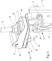
- eine Detaildarstellung einer eingebauten Sicherungsvorrichtung;
- Fig. 5
- eine Schnittdarstellung durch eine an einem Tor eingebaute Sicherungsvorrichtung;
- Fig. 6
- wie
Fig. 5 , jedoch mit einer Sicherungsvorrichtung im betätigten Zustand; - Fig. 7
- eine Sicherungsvorrichtung in einer perspektivischen Darstellung von unten gesehen;
- Fig. 8
- eine Draufsicht auf ein Oberteil der Sicherungsvorrichtung;
- Fig. 9
- einen Schnitt durch eine nicht erfindungsgemäße Ausführungsform einer Sicherungsvorrichtung im geschlossenen Zustand;
- Fig. 10
- wie
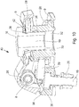
Fig. 9 , jedoch im geöffneten Zustand; - Fig. 11
- die Sicherungsvorrichtung gemäß
Fig. 9 ohne Verbindungselement; - Fig. 12
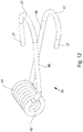
- eine bevorzugte Ausführung eines Federelementes in perspektivischer Darstellung, und
- Fig. 13
- eine perspektivische Darstellung der Sicherungsvorrichtung von der Rückseite betrachtet.
- Durch die Darstellung der
Fig. 1 wird ein Montageteil 3, welches mittels Schraubelementen 4 an einem nicht dargestellten Torblatt eines Tores, insbesondere eines Sektionaltores im unteren Bereich der letzten Sektion angebracht wird, wiedergegeben. Aus derFig. 1 ist im oberen Teil eine Sicherungsvorrichtung 1, 40 erkennbar, die mit einem Zugseil 5, welches über eine Umlenkung 11 geführt wird, verbunden ist. Der direkte Anschluss des Zugseils 5 über die Sicherungsvorrichtung 1, 40 und wird über eine Einstellschraube 6 in Verbindung mit einer Kontermutter 14 bewerkstelligt.
Die Umlenkung 11 ist auf einer gemeinsamen Achse 12 mit einer außen angebrachten Laufrolle 2 verbunden. Der Teil mit der Umlenkung 11 schützt eine Abdeckung 13.
In der Seitenansicht derFig. 2 wird deutlich, dass das Zugseil 5 zum Einen an der Sicherungsvorrichtung 1, 40 beispielsweise über eine Öse 25 angeschlossen ist und nach dem Verlassen der Umlenkung 11 geht das Zugseil 5 an eine nicht dargestellte angetriebene Wickelwelle, um eine Betätigung des Torblattes ausführen zu können. Für die bereits aus derFig. 1 bekannt gewordene Achse 12 ist innerhalb der Umlenkung 11 eine Bohrung 23 vorhanden.
Durch die Vorderansicht derFig. 3 wird noch einmal deutlich die Montage der Sicherungsvorrichtung 1, 40 im oberen Teil auf dem Montageteil 3 sichtbar. Dabei ist die Sicherungsvorrichtung 1, 40 mittels eines Schraubelementes 15 mit dem Montageteil 3 kraft- und formschlüssig verbunden. Ferner wird durch dieFig. 3 deutlich eine Seilanbindung 10 des Zugseiles 5. Gegen ein unbeabsichtigtes Verlassen des Zugseiles 5 aus der Umlenkung 11, beispielsweise bei einem Riss des Zugseiles 5, ist eine Zugseilsicherung 22 im Bereich der Umlenkung 11 vorhanden. Diese Zugseilsicherung 22 verhindert, dass beispielsweise bei einem Öffnen der Verbindung des Zugseiles 5 im Bereich der Öse 25 das Zugseil 5 aus der Umlenkung 11 heraus sich bewegt.
Die Sicherungsvorrichtung 1, 40 besteht im Wesentlichen aus einem Basisteil 9, das eine Ausnehmung 21 aufweist und mit dem Montageteil 3 über das Schraubelement 15 in Verbindung mit einer Mutter 20 befestigt ist. Durch die Ausnehmung 21 wird sichergestellt, dass beispielsweise eingetretenes Wasser nicht in der Sicherungsvorrichtung verbleibt und somit abfließen kann.
Mit dem Basisteil 9 ist über eine Drehachse 8 ein Oberteil 7 der Sicherungsvorrichtung 1, 40 verbunden. Innerhalb des Oberteils 7 ist, wie dieFig. 8 deutlich macht, ein Durchbruch 34 vorhanden. Der Durchbruch 34 ist oval ausgelegt und weist zu seinem Inneren vorstehende Mitnehmer 35 auf. Diese seitlichen Mitnehmer 35 haben vorzugsweise die Form eines Kreisbogenabschnittes oder dergleichen, wobei sich auf der oberen Rundung ein Verbindungselement 16 abstützt. Durch den Durchbruch 34 wird das Verbindungselement 16 sichtbar. Durch das Verbindungselement 16 geht die Einstellschraube 6, die durch die Kontermutter 14 gesichert wird. Über eine Längeneinstellung mittels der Einstellschraube 6 ist das, über die Öse 25 und die Seilanbindung 10, angeschlossene Zugseil 5 verbunden. - In einer teilweisen geschnittenen Darstellung wird gemäß der
Fig. 5 die erfindungsgemäße Ausführungsform der Sicherungsvorrichtung 1 in einer solchen Position wiedergegeben, die der Einbausituation derFig. 4 entspricht. Zur Übersichtlichkeit sind jedoch die Einstellschraube 6 und auch die Seilanbindung 10 nicht dargestellt worden.
Innerhalb des Basisteiles 9 ist eine runde Durchgangsbohrung 32 vorhanden, die von dem Verbindungselement 16 durchsetzt wird. Das Verbindungselement 16 ist dabei als kreisrundes Bauteil mit einem Führungsbereich 33 ausgeführt und weist im oberen Teil auf seinen Umfang eine umlaufende Vertiefung 26 auf. In diese Vertiefung 26 greifen die gemäß derFig. 8 bereits beschriebenen Mitnehmer 35 und ein Federelement 28 ein und gestatten es so, dass das Verbindungselement 16 schwimmend innerhalb das Oberteiles 7 eingebettet ist und bei einem Verschwenken des Oberteiles 7 um die Drehachse 8 kann durch die Kraft des Federelementes 28 das Verbindungselement 16 seine relative Lage verändern. In axialer Richtung ist innerhalb des Verbindungselementes 16 eine Bohrung 19 für die Verbindung zur Einstellschraube 6 vorhanden. Hier könnte auch ein nicht dargestelltes Gewinde innerhalb der Bohrung 19 vorhanden sein.
Die Sicherungsvorrichtung 1 ist mit einem Federelement 28 ausgestattet, das es erlaubt, bei einem Reißen des Zugseiles 5 die Lage des Oberteiles 7 gegenüber dem Basisteil 9 zu verändern. Dabei schmiegt oder stützt sich zum einen das Federelement 18 um das Basisteil 9 und das andere Federelementende 27 ist innerhalb der Vertiefung 26 des Verbindungselementes 16 eingebettet. Durch das Einbetten des Federelementendes 27 in das Verbindungselement 16 wird mit einem Ansprechen der Sicherungsvorrichtung 1 automatisch eine Lageveränderung des Verbindungselementes 16 die Drehachse 8 bewirkt. Durch die Mitnehmer 35 wird das Oberteil 7 durch das Verbindungselement 16 um den Drehpunkt verschwenkt. Diese Lageveränderung des Oberteiles 7 hat zur Folge, dass ein Sensor oder Schaltelement 29 über eine Betätigungskante 31 oder dergleichen, in diesem Falle unter Verwendung einer Schaltfahne 30, betätigt wird. Das Sensor- oder Schaltelement 29 ist elektrisch mit dem Motorkreislauf so verbunden, dass bei einem Ansprechen des Sensor- oder Schaltelementes 29 eine sofortige Stillsetzung des Motorantriebes bewirkt wird.
Aus derFig. 6 kann deutlich die Lageveränderung des Oberteiles 7 zum Basisteil 9 entnommen werden. Es wird deutlich, dass durch das Federelement 28 das Verbindungselement 16 seine relative Position zu dem Basisteil 9 verändert hat. Aus dieser Darstellung derFig. 6 kann auch das Ansprechen des Sensor- oder Schaltelementes 29 über eine Betätigungskante 31 und eine Schaltfahne 30 entnommen werden. Gleichzeitig ist an dem Oberteil 7 ein Anschlag 24, der die Schwenkbewegung des Oberteiles 7 gegenüber dem Basisteil 9 begrenzt.
Aus der Darstellung derFig. 7 , die die Sicherungsvorrichtung 1 von ihrer Unterseite aus sichtbar macht, kann insbesondere die durchlaufende Ausnehmung 21 entnommen werden, durch die ein Ablaufen von eingetretenem Wasser bewirkt wird. - Durch die
Fig. 9 wird eine weitere nicht erfindungsgemäße Ausführungsform einer Sicherungsvorrichtung 40 bekannt. In diesem Ausführungsbeispiel wird das Verbindungselement 16 nicht durch das Federelement 28 belastet. Auch bei dieser Ausführungsform liegt das Verbindungselement 16 auf den Mitnehmern 35 schwimmend auf. Somit stützt sich das Federelement 28 mit seinen Federenden 27 auf dem Basisteil 9 und gegen das Oberteil 7 ab. Das Verbindungselement 16 weist unterhalb seines oberen Randes eine umlaufende Nut auf, die in derFig. 9 mit einer Halbbohrung 36 innerhalb des Basisteiles 7 korrespondiert. Gleichzeitig fluchtet die Halbbohrung 36 mit einer Haltefläche 42 des Oberteiles 7. So ist es möglich, dass ein Sicherungselement 49 durch die Halbbohrung 36 geschoben wird, um die Sicherungsvorrichtung 40 gegen die Federkraft zusammenzuhalten, und um die Montage zu erleichtern (Fig. 13 ).
Die Stellung der Sicherungsvorrichtung 40 mit durch das Federelement 28 angehobenen Oberteil 7 kann derFig. 10 entnommen werden. Deutlich wird hier auch das Anheben des Verbindungselementes 16.
In der Darstellung derFig. 11 kann durch das Fehlen des Verbindungselementes 16 der Bereich des Mitnehmers 35 und die Verbindungsstrecke für das Sicherungselement 49 sichtbar. Das hier nicht dargestellte Sicherungselement 49 geht dabei durch eine Bohrung 43 des Basisteiles 9 und damit fluchtenden Halteflächen 42 in der Oberteil 7 über. Wenn nach der Montage das Sicherungselement 49 nicht mehr gebraucht wird, kann es in eine Parkbohrung 48 gesteckt werden. Das Sicherungselement 49 kann aber auch zu Prüfzwecken des Sensor- oder Schaltelementes 29 über eine Öffnung 38 verwendet werden. An der Sicherungsvorrichtung 40 ist eine elektrische Verbindung 39 vorhanden. Die Drehachse 8 wird durch ein Sicherungselement 41 gesichert. - Das innerhalb der Sicherungsvorrichtung 1, 40 verwendete Federelement 28 kann in einer Einzeldarstellung der
Fig. 12 näher betrachtet werden. Ausgehend von einem Wickel 44 mit einem Aufnahmebereich 45 für die Drehachse 8 sind zwei in der Ruhestellung gespreizte Federarme 46 vorhanden, die in gegeneinander gebogene Bereiche 47 in den Federelementenden 27 enden. -
- 1.
- Sicherungsvorrichtung
- 2.
- Laufrolle
- 3.
- Montageteil
- 4.
- Schraubelement
- 5.
- Zugseil
- 6.
- Einstellschraube
- 7.
- Oberteil
- 8.
- Drehachse
- 9.
- Basisteil
- 10.
- Seilanbindung
- 11.
- Umlenkung
- 12.
- Achse
- 13.
- Abdeckung
- 14.
- Kontermutter
- 15.
- Schraubelement
- 16.
- Verbindungselement
- 17.
- Durchbruch
- 18.
- Führungshülse
- 19.
- Bohrung
- 20.
- Mutter
- 21.
- Ausnehmung
- 22.
- Zugseilsicherung
- 23.
- Bohrung
- 24.
- Anschlag
- 25.
- Öse
- 26.
- Vertiefung
- 27.
- Federelementende
- 28.
- Federelement
- 29.
- Sensor oder Schaltelement
- 30.
- Schaltfahne
- 31.
- Betätigungskante
- 32.
- Durchgangsbohrung
- 33.
- Führungsbereich
- 34.
- Durchbruch
- 35.
- Mitnehmer
- 36.
- Halbbohrung
- 37.
- Flansch
- 38.
- Öffnung
- 39.
- elektrische Verbindung
- 40.
- Sicherungsvorrichtung
- 41.
- Sicherungselement
- 42.
- Haltefläche
- 43.
- Bohrung
- 44.
- Wickel
- 45.
- Aufnahmebereich
- 46.
- Federarm
- 47.
- gebogener Bereich
- 48.
- Parkbohrung
- 49.
- Sicherungselement
Claims (3)
- Sicherungsvorrichtung (1, 40) für ein ortsveränderbares Torblatt eines Tores, insbesondere eines Sektionaltores, das zwischen einer Öffnungsstellung und einer Schließstellung über Führungsschienen verfahren wird, wobei das Torblatt seitlich mit Zugseilen (5) ausgestattet ist, die im unteren Bereich des Torblattes befestigt und jeweils über Umlenkungen (11) geführt sind, wobei die Befestigung mindestens eines Zugseiles (5) über die Sicherungsvorrichtung (1, 40) so ausgeführt ist, dass bei geschlossenem Torblatt eine stufenlose Einstellung der Zugseillänge gegeben ist, wobei die Sicherungsvorrichtung (1, 40) aus einem feststehenden Basisteil (9) und über eine Drehachse (8) in seiner Position zum Basisteil (9) veränderbarem Oberteil mit darin beweglich gelagertem Verbindungselement (16) besteht, wobei eine Längenänderung des Zugseiles (5) von dem Oberteil (7) erfasst und durch ein Sensor- oder Schaltelement (29) der Sicherungsvorrichtung (1, 40) detektiert wird, dadurch gekennzeichnet, dass das Verbindungselement (16) als kreisrundes Bauteil mit einem Führungsbereich (33) ausgebildet ist und im oberen Teil auf seinem Umfang eine umlaufende Vertiefung (26) aufweist, wobei das Oberteil (7) einen ovalförmigen Durchbruch (34) mit seitlich vorstehenden Mitnehmern (35) aufweist, die in die Vertiefung (26) des Verbindungselements (16) eingreifen, wobei die Sicherungsvorrichtung (1, 40) ferner ein Federelement (28) aufweist, welches sich zum einen um das Basisteil (9) schmiegt oder stützt, wobei das andere Federelementende (27) innerhalb der Vertiefung (26) des Verbindungselements (16) eingebettet ist, wobei das Verbindungselement (16) in dem Oberteil (7) schwimmend gelagert in einer Durchgangsbohrung (32) des Basisteils (9) geführt wird, wobei innerhalb des Verbindungelements (16) in axialer Richtung eine Bohrung (19) vorhanden ist, durch die eine Einstellschraube (6) geht, die durch eine Kontermutter (14) gesichert wird, wobei das Zugseil (5) über eine Seilanordnung (10) und eine Öse (25) an der Einstellschraube (6) anschließbar ist, wodurch das Zugseil (5) über eine Längeneinstellung mittels der Einstellschraube (6) mit der Sicherungsvorrichtung (1, 40) verbindbar ist, so dass bei einem Reißen oder Entspannen des Zeugseiles (5) sich die Lage des Oberteils (7) durch das Federelement (28) gegenüber dem Basisteil (9) verändert, dabei wird das Oberteil (7) durch das Verbindungselement (16) über die Mitnehmer (35) so um die Drehachse (8) verschwenkt, dass der Sensor oder das Schaltelement (29) über eine an dem Oberteil (7) vorhandene Betätigungskante (31) betätigt wird.
- Sicherungsvorrichtung nach Anspruch 1, dadurch gekennzeichnet, dass ein- durch die Betätigungskante (31) über den Sensor- oder das Schaltelement (29) direkt oder indirekt erzeugtes Signal direkt oder indirekt in einen Motorfunktionskreis eingreifen kann.
- Tor, insbesondere Sektionaltor, mit mindestens einer Sicherungsvorrichtung (1, 40) gemäß den vorhergehenden Ansprüchen.
Priority Applications (1)
| Application Number | Priority Date | Filing Date | Title |
|---|---|---|---|
| PL12164707T PL2514896T3 (pl) | 2011-04-20 | 2012-04-19 | Urządzenie zabezpieczające |
Applications Claiming Priority (1)
| Application Number | Priority Date | Filing Date | Title |
|---|---|---|---|
| DE202011000948U DE202011000948U1 (de) | 2011-04-20 | 2011-04-20 | Sicherungsvorrichtung |
Publications (3)
| Publication Number | Publication Date |
|---|---|
| EP2514896A2 EP2514896A2 (de) | 2012-10-24 |
| EP2514896A3 EP2514896A3 (de) | 2014-12-17 |
| EP2514896B1 true EP2514896B1 (de) | 2018-11-28 |
Family
ID=44317500
Family Applications (1)
| Application Number | Title | Priority Date | Filing Date |
|---|---|---|---|
| EP12164707.7A Active EP2514896B1 (de) | 2011-04-20 | 2012-04-19 | Sicherungsvorrichtung |
Country Status (5)
| Country | Link |
|---|---|
| EP (1) | EP2514896B1 (de) |
| DE (1) | DE202011000948U1 (de) |
| DK (1) | DK2514896T3 (de) |
| ES (1) | ES2713093T3 (de) |
| PL (1) | PL2514896T3 (de) |
Cited By (1)
| Publication number | Priority date | Publication date | Assignee | Title |
|---|---|---|---|---|
| EP3819452A1 (de) | 2019-11-08 | 2021-05-12 | Alpha Deuren International BV | Tor |
Families Citing this family (5)
| Publication number | Priority date | Publication date | Assignee | Title |
|---|---|---|---|---|
| DE102018103745B4 (de) | 2018-02-20 | 2024-09-26 | Cedes Ag | Schlaffseilsicherungsanordnung für ein Antriebszugmittel |
| DE102020104577B3 (de) * | 2020-02-21 | 2021-01-21 | Alpha Deuren International Bv | Elektrisches Schaltelement |
| EP4314457A1 (de) * | 2021-03-25 | 2024-02-07 | ASSA ABLOY Entrance Systems AB | Überwachungsanordnung in einem deckensektionaltor |
| DE202024106393U1 (de) | 2024-11-08 | 2024-12-06 | Alcomex Beheer Bv | Tragseilüberwachungseinheit für ein Torblatt |
| DE202024106394U1 (de) | 2024-11-08 | 2024-12-23 | Alcomex Beheer Bv | Tragseilüberwachungseinheit für ein Torblatt |
Family Cites Families (6)
| Publication number | Priority date | Publication date | Assignee | Title |
|---|---|---|---|---|
| DE7912249U1 (de) | 1979-04-26 | 1979-09-06 | Tuerenwerke Riexinger Gmbh & Co Kg, 7129 Brackenheim | Seilzug mit toraufhaenger und darin eingebauter schlaffseilsicherung fuer ein deckenglieder- oder rolltor |
| DE29503553U1 (de) * | 1995-01-05 | 1996-05-09 | MARANTEC Antriebs- und Steuerungstechnik GmbH & Co. Produktions-KG, 33428 Marienfeld | Überwachungseinrichtung für ein Tragseil eines Torblattes |
| CA2263666A1 (en) * | 1999-03-18 | 2000-09-18 | Pierre-Louis Foucault | Cable failure device |
| DE10113847A1 (de) | 2001-03-21 | 2002-09-26 | Hoermann Kg | Sicherungsvorrichtung |
| DE20204194U1 (de) * | 2002-03-15 | 2003-07-24 | Marantec Antriebs- und Steuerungstechnik GmbH & Co. KG, 33428 Marienfeld | Sicherheitsschaltereinrichtung zum Schalten eines Torantriebes |
| NL1030916C2 (nl) * | 2006-01-13 | 2007-07-17 | Flexi Force B V | Kabelbreukbeveiligingsmechanisme. |
-
2011
- 2011-04-20 DE DE202011000948U patent/DE202011000948U1/de not_active Expired - Lifetime
-
2012
- 2012-04-19 ES ES12164707T patent/ES2713093T3/es active Active
- 2012-04-19 PL PL12164707T patent/PL2514896T3/pl unknown
- 2012-04-19 EP EP12164707.7A patent/EP2514896B1/de active Active
- 2012-04-19 DK DK12164707.7T patent/DK2514896T3/en active
Non-Patent Citations (1)
| Title |
|---|
| None * |
Cited By (1)
| Publication number | Priority date | Publication date | Assignee | Title |
|---|---|---|---|---|
| EP3819452A1 (de) | 2019-11-08 | 2021-05-12 | Alpha Deuren International BV | Tor |
Also Published As
| Publication number | Publication date |
|---|---|
| DK2514896T3 (en) | 2019-03-11 |
| EP2514896A3 (de) | 2014-12-17 |
| EP2514896A2 (de) | 2012-10-24 |
| ES2713093T3 (es) | 2019-05-17 |
| DE202011000948U1 (de) | 2011-06-28 |
| PL2514896T3 (pl) | 2019-05-31 |
Similar Documents
| Publication | Publication Date | Title |
|---|---|---|
| DE102012014696B4 (de) | Dachträger für ein Kraftfahrzeug, Verfahren zum Betreiben eines Steuergeräts eines Kraftfahrzeugs sowie entsprechendes Steuergerät | |
| DE102012111397B4 (de) | Motorhaubenverriegelungsvorrichtung mit Zwei-Stufen-Führung für ein Fahrzeug | |
| DE3815890C2 (de) | Fernbetätigter Riegelmechanismus | |
| EP2514896A2 (de) | Sicherungsvorrichtung | |
| EP3066282B1 (de) | Schliesseinrichtung für eine tür oder klappe | |
| DE102020122059B4 (de) | Antriebseinrichtung für eine Klappe | |
| EP2874933B1 (de) | Aufzugsanlage mit sicherheitsvorrichtung | |
| EP2634785A1 (de) | Schaltvorrichtung | |
| DE202004017769U1 (de) | Linearantrieb | |
| DE102017209719A1 (de) | Fensterheberbaugruppe mit Sicherungselement und Sicherungsabschnitt für die Sicherung eines Zugmittels | |
| EP3667010B1 (de) | Anschlagvorrichtung für eine automatische türdichtung, insbesondere für eine pivot- oder pendeltür, anordnung aus einer automatischen türdichtung und einer anschlagvorrichtung | |
| EP3394368A1 (de) | Kraftfahrzeugschloss mit drehfallenabstützung | |
| DE19949186A1 (de) | Türscharnier | |
| DE102009039623A1 (de) | Torantriebsvorrichtung mit Zugmittelüberwachungseinrichtung sowie damit versehenes Tor | |
| EP2877372B1 (de) | Dachträgereinrichtung für ein kraftfahrzeug | |
| DE102012000452A1 (de) | Vorrichtung zum Verriegeln einer Fahrzeugtür | |
| EP3166373B1 (de) | Klemmmodul zur befestigung an einer tragschiene | |
| DE19855697A1 (de) | Federbruchsicherung | |
| EP3870788B1 (de) | Fensterhebersystem und kraftfahrzeugtür | |
| DE102009043395A1 (de) | Stabilisator für den unteren Anschlag eines Fensterglases bei einer Fahrzeugtür | |
| DE102009024551A1 (de) | Zaunpfosten mit verschwenkbarem Ausleger | |
| DE2917023A1 (de) | Seilzug mit toraufhaenger und darin eingebauter schlaffseilsicherung fuer ein deckenglieder- oder rolltor | |
| EP3163007B1 (de) | Vorrichtung zur endabschaltung einer motorischen antriebsvorrichtung einer wickelwelle eines rollladens | |
| DE102005002878A1 (de) | Verschluss an einer Tür oder Klappe eines Fahrzeugs | |
| DE7912249U1 (de) | Seilzug mit toraufhaenger und darin eingebauter schlaffseilsicherung fuer ein deckenglieder- oder rolltor |
Legal Events
| Date | Code | Title | Description |
|---|---|---|---|
| PUAI | Public reference made under article 153(3) epc to a published international application that has entered the european phase |
Free format text: ORIGINAL CODE: 0009012 |
|
| AK | Designated contracting states |
Kind code of ref document: A2 Designated state(s): AL AT BE BG CH CY CZ DE DK EE ES FI FR GB GR HR HU IE IS IT LI LT LU LV MC MK MT NL NO PL PT RO RS SE SI SK SM TR |
|
| AX | Request for extension of the european patent |
Extension state: BA ME |
|
| PUAL | Search report despatched |
Free format text: ORIGINAL CODE: 0009013 |
|
| AK | Designated contracting states |
Kind code of ref document: A3 Designated state(s): AL AT BE BG CH CY CZ DE DK EE ES FI FR GB GR HR HU IE IS IT LI LT LU LV MC MK MT NL NO PL PT RO RS SE SI SK SM TR |
|
| AX | Request for extension of the european patent |
Extension state: BA ME |
|
| RIC1 | Information provided on ipc code assigned before grant |
Ipc: E05D 13/00 20060101AFI20141107BHEP Ipc: E05F 15/18 20060101ALN20141107BHEP Ipc: E05F 15/00 20060101ALN20141107BHEP |
|
| 17P | Request for examination filed |
Effective date: 20150616 |
|
| RBV | Designated contracting states (corrected) |
Designated state(s): AL AT BE BG CH CY CZ DE DK EE ES FI FR GB GR HR HU IE IS IT LI LT LU LV MC MK MT NL NO PL PT RO RS SE SI SK SM TR |
|
| 17Q | First examination report despatched |
Effective date: 20160915 |
|
| STAA | Information on the status of an ep patent application or granted ep patent |
Free format text: STATUS: EXAMINATION IS IN PROGRESS |
|
| GRAP | Despatch of communication of intention to grant a patent |
Free format text: ORIGINAL CODE: EPIDOSNIGR1 |
|
| STAA | Information on the status of an ep patent application or granted ep patent |
Free format text: STATUS: GRANT OF PATENT IS INTENDED |
|
| RIC1 | Information provided on ipc code assigned before grant |
Ipc: E05F 15/00 20060101ALN20180619BHEP Ipc: E05D 13/00 20060101AFI20180619BHEP Ipc: E05F 15/41 20150101ALN20180619BHEP |
|
| INTG | Intention to grant announced |
Effective date: 20180720 |
|
| GRAS | Grant fee paid |
Free format text: ORIGINAL CODE: EPIDOSNIGR3 |
|
| GRAA | (expected) grant |
Free format text: ORIGINAL CODE: 0009210 |
|
| STAA | Information on the status of an ep patent application or granted ep patent |
Free format text: STATUS: THE PATENT HAS BEEN GRANTED |
|
| AK | Designated contracting states |
Kind code of ref document: B1 Designated state(s): AL AT BE BG CH CY CZ DE DK EE ES FI FR GB GR HR HU IE IS IT LI LT LU LV MC MK MT NL NO PL PT RO RS SE SI SK SM TR |
|
| REG | Reference to a national code |
Ref country code: GB Ref legal event code: FG4D Free format text: NOT ENGLISH |
|
| REG | Reference to a national code |
Ref country code: CH Ref legal event code: EP |
|
| REG | Reference to a national code |
Ref country code: AT Ref legal event code: REF Ref document number: 1070436 Country of ref document: AT Kind code of ref document: T Effective date: 20181215 |
|
| REG | Reference to a national code |
Ref country code: DE Ref legal event code: R096 Ref document number: 502012013895 Country of ref document: DE |
|
| REG | Reference to a national code |
Ref country code: IE Ref legal event code: FG4D Free format text: LANGUAGE OF EP DOCUMENT: GERMAN |
|
| REG | Reference to a national code |
Ref country code: DK Ref legal event code: T3 Effective date: 20190304 |
|
| REG | Reference to a national code |
Ref country code: SE Ref legal event code: TRGR |
|
| REG | Reference to a national code |
Ref country code: NL Ref legal event code: FP |
|
| REG | Reference to a national code |
Ref country code: LT Ref legal event code: MG4D |
|
| PG25 | Lapsed in a contracting state [announced via postgrant information from national office to epo] |
Ref country code: IS Free format text: LAPSE BECAUSE OF FAILURE TO SUBMIT A TRANSLATION OF THE DESCRIPTION OR TO PAY THE FEE WITHIN THE PRESCRIBED TIME-LIMIT Effective date: 20190328 Ref country code: NO Free format text: LAPSE BECAUSE OF FAILURE TO SUBMIT A TRANSLATION OF THE DESCRIPTION OR TO PAY THE FEE WITHIN THE PRESCRIBED TIME-LIMIT Effective date: 20190228 Ref country code: LT Free format text: LAPSE BECAUSE OF FAILURE TO SUBMIT A TRANSLATION OF THE DESCRIPTION OR TO PAY THE FEE WITHIN THE PRESCRIBED TIME-LIMIT Effective date: 20181128 Ref country code: BG Free format text: LAPSE BECAUSE OF FAILURE TO SUBMIT A TRANSLATION OF THE DESCRIPTION OR TO PAY THE FEE WITHIN THE PRESCRIBED TIME-LIMIT Effective date: 20190228 Ref country code: HR Free format text: LAPSE BECAUSE OF FAILURE TO SUBMIT A TRANSLATION OF THE DESCRIPTION OR TO PAY THE FEE WITHIN THE PRESCRIBED TIME-LIMIT Effective date: 20181128 Ref country code: LV Free format text: LAPSE BECAUSE OF FAILURE TO SUBMIT A TRANSLATION OF THE DESCRIPTION OR TO PAY THE FEE WITHIN THE PRESCRIBED TIME-LIMIT Effective date: 20181128 Ref country code: FI Free format text: LAPSE BECAUSE OF FAILURE TO SUBMIT A TRANSLATION OF THE DESCRIPTION OR TO PAY THE FEE WITHIN THE PRESCRIBED TIME-LIMIT Effective date: 20181128 |
|
| REG | Reference to a national code |
Ref country code: ES Ref legal event code: FG2A Ref document number: 2713093 Country of ref document: ES Kind code of ref document: T3 Effective date: 20190517 |
|
| PG25 | Lapsed in a contracting state [announced via postgrant information from national office to epo] |
Ref country code: RS Free format text: LAPSE BECAUSE OF FAILURE TO SUBMIT A TRANSLATION OF THE DESCRIPTION OR TO PAY THE FEE WITHIN THE PRESCRIBED TIME-LIMIT Effective date: 20181128 Ref country code: AL Free format text: LAPSE BECAUSE OF FAILURE TO SUBMIT A TRANSLATION OF THE DESCRIPTION OR TO PAY THE FEE WITHIN THE PRESCRIBED TIME-LIMIT Effective date: 20181128 Ref country code: GR Free format text: LAPSE BECAUSE OF FAILURE TO SUBMIT A TRANSLATION OF THE DESCRIPTION OR TO PAY THE FEE WITHIN THE PRESCRIBED TIME-LIMIT Effective date: 20190301 Ref country code: PT Free format text: LAPSE BECAUSE OF FAILURE TO SUBMIT A TRANSLATION OF THE DESCRIPTION OR TO PAY THE FEE WITHIN THE PRESCRIBED TIME-LIMIT Effective date: 20190328 |
|
| PG25 | Lapsed in a contracting state [announced via postgrant information from national office to epo] |
Ref country code: IT Free format text: LAPSE BECAUSE OF FAILURE TO SUBMIT A TRANSLATION OF THE DESCRIPTION OR TO PAY THE FEE WITHIN THE PRESCRIBED TIME-LIMIT Effective date: 20181128 Ref country code: CZ Free format text: LAPSE BECAUSE OF FAILURE TO SUBMIT A TRANSLATION OF THE DESCRIPTION OR TO PAY THE FEE WITHIN THE PRESCRIBED TIME-LIMIT Effective date: 20181128 |
|
| REG | Reference to a national code |
Ref country code: DE Ref legal event code: R097 Ref document number: 502012013895 Country of ref document: DE |
|
| PG25 | Lapsed in a contracting state [announced via postgrant information from national office to epo] |
Ref country code: SM Free format text: LAPSE BECAUSE OF FAILURE TO SUBMIT A TRANSLATION OF THE DESCRIPTION OR TO PAY THE FEE WITHIN THE PRESCRIBED TIME-LIMIT Effective date: 20181128 Ref country code: SK Free format text: LAPSE BECAUSE OF FAILURE TO SUBMIT A TRANSLATION OF THE DESCRIPTION OR TO PAY THE FEE WITHIN THE PRESCRIBED TIME-LIMIT Effective date: 20181128 Ref country code: EE Free format text: LAPSE BECAUSE OF FAILURE TO SUBMIT A TRANSLATION OF THE DESCRIPTION OR TO PAY THE FEE WITHIN THE PRESCRIBED TIME-LIMIT Effective date: 20181128 Ref country code: RO Free format text: LAPSE BECAUSE OF FAILURE TO SUBMIT A TRANSLATION OF THE DESCRIPTION OR TO PAY THE FEE WITHIN THE PRESCRIBED TIME-LIMIT Effective date: 20181128 |
|
| PLBE | No opposition filed within time limit |
Free format text: ORIGINAL CODE: 0009261 |
|
| STAA | Information on the status of an ep patent application or granted ep patent |
Free format text: STATUS: NO OPPOSITION FILED WITHIN TIME LIMIT |
|
| PG25 | Lapsed in a contracting state [announced via postgrant information from national office to epo] |
Ref country code: SI Free format text: LAPSE BECAUSE OF FAILURE TO SUBMIT A TRANSLATION OF THE DESCRIPTION OR TO PAY THE FEE WITHIN THE PRESCRIBED TIME-LIMIT Effective date: 20181128 |
|
| 26N | No opposition filed |
Effective date: 20190829 |
|
| REG | Reference to a national code |
Ref country code: CH Ref legal event code: PL |
|
| PG25 | Lapsed in a contracting state [announced via postgrant information from national office to epo] |
Ref country code: LU Free format text: LAPSE BECAUSE OF NON-PAYMENT OF DUE FEES Effective date: 20190419 Ref country code: MC Free format text: LAPSE BECAUSE OF FAILURE TO SUBMIT A TRANSLATION OF THE DESCRIPTION OR TO PAY THE FEE WITHIN THE PRESCRIBED TIME-LIMIT Effective date: 20181128 |
|
| PG25 | Lapsed in a contracting state [announced via postgrant information from national office to epo] |
Ref country code: LI Free format text: LAPSE BECAUSE OF NON-PAYMENT OF DUE FEES Effective date: 20190430 Ref country code: CH Free format text: LAPSE BECAUSE OF NON-PAYMENT OF DUE FEES Effective date: 20190430 |
|
| PG25 | Lapsed in a contracting state [announced via postgrant information from national office to epo] |
Ref country code: TR Free format text: LAPSE BECAUSE OF FAILURE TO SUBMIT A TRANSLATION OF THE DESCRIPTION OR TO PAY THE FEE WITHIN THE PRESCRIBED TIME-LIMIT Effective date: 20181128 |
|
| PG25 | Lapsed in a contracting state [announced via postgrant information from national office to epo] |
Ref country code: IE Free format text: LAPSE BECAUSE OF NON-PAYMENT OF DUE FEES Effective date: 20190419 |
|
| REG | Reference to a national code |
Ref country code: AT Ref legal event code: MM01 Ref document number: 1070436 Country of ref document: AT Kind code of ref document: T Effective date: 20190419 |
|
| PG25 | Lapsed in a contracting state [announced via postgrant information from national office to epo] |
Ref country code: AT Free format text: LAPSE BECAUSE OF NON-PAYMENT OF DUE FEES Effective date: 20190419 |
|
| PG25 | Lapsed in a contracting state [announced via postgrant information from national office to epo] |
Ref country code: CY Free format text: LAPSE BECAUSE OF FAILURE TO SUBMIT A TRANSLATION OF THE DESCRIPTION OR TO PAY THE FEE WITHIN THE PRESCRIBED TIME-LIMIT Effective date: 20181128 |
|
| PG25 | Lapsed in a contracting state [announced via postgrant information from national office to epo] |
Ref country code: MT Free format text: LAPSE BECAUSE OF FAILURE TO SUBMIT A TRANSLATION OF THE DESCRIPTION OR TO PAY THE FEE WITHIN THE PRESCRIBED TIME-LIMIT Effective date: 20181128 Ref country code: HU Free format text: LAPSE BECAUSE OF FAILURE TO SUBMIT A TRANSLATION OF THE DESCRIPTION OR TO PAY THE FEE WITHIN THE PRESCRIBED TIME-LIMIT; INVALID AB INITIO Effective date: 20120419 |
|
| PG25 | Lapsed in a contracting state [announced via postgrant information from national office to epo] |
Ref country code: MK Free format text: LAPSE BECAUSE OF FAILURE TO SUBMIT A TRANSLATION OF THE DESCRIPTION OR TO PAY THE FEE WITHIN THE PRESCRIBED TIME-LIMIT Effective date: 20181128 |
|
| PGFP | Annual fee paid to national office [announced via postgrant information from national office to epo] |
Ref country code: NL Payment date: 20250418 Year of fee payment: 14 |
|
| PGFP | Annual fee paid to national office [announced via postgrant information from national office to epo] |
Ref country code: PL Payment date: 20250410 Year of fee payment: 14 Ref country code: DE Payment date: 20250422 Year of fee payment: 14 |
|
| PGFP | Annual fee paid to national office [announced via postgrant information from national office to epo] |
Ref country code: GB Payment date: 20250423 Year of fee payment: 14 Ref country code: ES Payment date: 20250529 Year of fee payment: 14 Ref country code: DK Payment date: 20250429 Year of fee payment: 14 |
|
| PGFP | Annual fee paid to national office [announced via postgrant information from national office to epo] |
Ref country code: BE Payment date: 20250418 Year of fee payment: 14 |
|
| PGFP | Annual fee paid to national office [announced via postgrant information from national office to epo] |
Ref country code: FR Payment date: 20250425 Year of fee payment: 14 |
|
| PGFP | Annual fee paid to national office [announced via postgrant information from national office to epo] |
Ref country code: SE Payment date: 20250429 Year of fee payment: 14 |