EP2514918A1 - Trépan tranchant et porte-pointes - Google Patents
Trépan tranchant et porte-pointes Download PDFInfo
- Publication number
- EP2514918A1 EP2514918A1 EP20110163236 EP11163236A EP2514918A1 EP 2514918 A1 EP2514918 A1 EP 2514918A1 EP 20110163236 EP20110163236 EP 20110163236 EP 11163236 A EP11163236 A EP 11163236A EP 2514918 A1 EP2514918 A1 EP 2514918A1
- Authority
- EP
- European Patent Office
- Prior art keywords
- bit
- holder
- cutting
- cutting bit
- surface portion
- Prior art date
- Legal status (The legal status is an assumption and is not a legal conclusion. Google has not performed a legal analysis and makes no representation as to the accuracy of the status listed.)
- Granted
Links
- 238000005553 drilling Methods 0.000 claims abstract description 5
- 238000003801 milling Methods 0.000 claims abstract description 5
- 238000005065 mining Methods 0.000 claims abstract description 5
- 239000000463 material Substances 0.000 claims description 12
- 230000003993 interaction Effects 0.000 claims description 7
- 230000007704 transition Effects 0.000 description 11
- 230000000295 complement effect Effects 0.000 description 4
- 229910003460 diamond Inorganic materials 0.000 description 4
- 239000010432 diamond Substances 0.000 description 4
- 229910000831 Steel Inorganic materials 0.000 description 3
- 239000010959 steel Substances 0.000 description 3
- 229910052582 BN Inorganic materials 0.000 description 2
- PZNSFCLAULLKQX-UHFFFAOYSA-N Boron nitride Chemical compound N#B PZNSFCLAULLKQX-UHFFFAOYSA-N 0.000 description 2
- 230000008901 benefit Effects 0.000 description 2
- 230000005540 biological transmission Effects 0.000 description 2
- 238000007545 Vickers hardness test Methods 0.000 description 1
- 238000010521 absorption reaction Methods 0.000 description 1
- 229910052799 carbon Inorganic materials 0.000 description 1
- -1 carbon nitrides Chemical class 0.000 description 1
- 230000003247 decreasing effect Effects 0.000 description 1
- 230000001419 dependent effect Effects 0.000 description 1
- 239000000428 dust Substances 0.000 description 1
- 238000005516 engineering process Methods 0.000 description 1
- 230000002452 interceptive effect Effects 0.000 description 1
- 239000002073 nanorod Substances 0.000 description 1
Images


Classifications
-
- E—FIXED CONSTRUCTIONS
- E21—EARTH OR ROCK DRILLING; MINING
- E21C—MINING OR QUARRYING
- E21C35/00—Details of, or accessories for, machines for slitting or completely freeing the mineral from the seam, not provided for in groups E21C25/00 - E21C33/00, E21C37/00 or E21C39/00
- E21C35/18—Mining picks; Holders therefor
- E21C35/19—Means for fixing picks or holders
Definitions
- the present disclosure relates to a rotatable bit and a bit holder for use in a heavy-duty mining or drilling apparatus or in a road milling apparatus.
- the disclosure particularly relates to so-called "pick type bits”.
- a drive body which may have the form of e.g. a drum or a drill head, is provided with a number of replaceable bits, which present a very hard cutting point.
- Non-limiting examples of such drive bodies are shown in Figs 1 and 14-20 of US2008/258536A1 .
- the bit shown in US2008/258536A1 comprises a head portion, which may be approximately conical and taper towards a cutting point; and a shank, which is insertable into a bit holder.
- the bit is a wear part, and hence it is desirable to be able to rapidly replace worn bits, and also to produce such bits at as low cost as possible.
- the bit holder is, in turn, fixedly connected to the drive body.
- the functions of the bit holder are to ensure that the bit is angled in the desired direction and to replaceably receive the bit.
- the bit holder may be integrated with the drive body, it may be formed in one piece with the drive body, or it may be attached to the drive body.
- the bit holder may protrude more or less from the surface of the drive body.
- US 5,261,499 discloses a drill bit, which is designed according to the principles set forth above, and where the head portion of the bit is rotatable relative to the shank, which serves to distribute wear more evenly over the head portion.
- US 3,342,531 discloses various drill bit designs, which provide strictly conical bit heads, which are attachable on a shank, which is in turn attachable to a bit holder.
- US 2008/0309148A1 shows a bit design according to the precharacterizing portion of claim 1.
- a single tip cutting bit for use in a heavy-duty mining, drilling or milling operation.
- the cutting bit comprises a generally conical body, a first end of which presenting a cutting point and a second end of which presenting an axially extending recess, presenting a generally convex surface portion and having locking means for releasably and rotatably connecting the cutting bit to a protruding part of a bit holder.
- the recess has an entrance portion presenting a generally conical surface portion.
- generally conical should be construed to include also frustoconical bodies, and other bodies which are rotationally symmetrical, or approximately so, with a generally conical cross section.
- the "entrance portion” is a portion which is situated inside the recess, at the second end of the conical body, and which is designed to be active in force transfer between the bit and the bit holder.
- the rotatable connection may be so conceived that the bit and bit holder are rotatable relative to each other when the bit is subjected no or a relatively small load, while the bit and bit holder may not be rotatable relative to each other upon being subjected to greater loads. Between cuts, there may be a relatively loose contact, or even a small play between the interacting conical/convex surfaces and/or conical surfaces.
- the convex surface portion and the conical entrance portion provide for effective load transmission.
- the interaction between conical and convex/concave surfaces provides for improved absorption of impact loads through the tapered surfaces, with increased resistance to shear loads.
- the claimed geometry also operates to self-center the bit onto the bit holder, which is advantageous from a force transfer perspective.
- the disclosed design allows for a larger protruding part without having to weaken the bit by too much removal of material.
- the locking means may be spaced inwardly from an opening of the recess.
- the convex surface portion may be positioned between the locking means and an opening of the recess.
- the convex surface portion may be positioned between the conical surface portion and the locking means.
- a distance from a base of conical body to an innermost portion of the locking means is less than or equal to half a total height of the generally conical body.
- a radius of the convex surface portion is greater than or equal to 1 ⁇ 4 of a distance from a base of the conical body to an innermost portion of the locking means.
- a radius of the convex surface portion is less than or equal to twice a distance from a base of the conical body to an innermost portion of the locking means.
- An outer surface portion of the conical body may be generally concave.
- the locking means may comprise a bearing. Hence, relative rotational movement is facilitated.
- the generally conical body may be formed mainly of steel and/or carbide.
- the cutting point may be at least coated with a super hard material, or a combination of super hard materials.
- the cutting point may thus be formed partly or entirely of the super hard material or materials.
- Super hard materials may be defined as materials having a hardness value exceeding 40 GPa (gigapascals) when measured by the Vickers hardness test, and include, but are not limited to, diamond, cubic boron nitride, carbon nitrides and aggregated diamond nanorods.
- a bit holder for a cutting bit.
- the bit holder comprises a holder body, a protruding part, extending from the holder body, and being adapted to extend into a recess of a cutting bit as claimed in any one of the preceding claims, and locking means positioned on the protruding part for releasably locking the cutting bit to the bit holder.
- the protruding part presents a concave surface portion, adapted for abutment against the convex surface portion of the cutting bit.
- the holder has a shoulder portion presenting a generally conical surface portion, for interaction with the entrance portion of the cutting bit.
- the "holder body” is a body which attaches in a relatively permanent manner to a drive body, and which receives the more easily replaceable cutting bit.
- the "shoulder portion” is a portion which is situated at the transition from the protrusion to the holder body, and which thus presents an outwardly facing conical surface portion.
- the concave surface portion provides for effective load transmission.
- the bit holder may be adapted for being permanently secured to a drive body.
- the protruding part and the holder body are formed in one piece.
- the one piece arrangement provides increased resistance against fatigue, as compared with an arrangement where the protruding part is formed of a separate part, which is attached to the holder body.
- a system comprising a cutting bit as described above and a bit holder as described above.
- a second end of the cutting bit may extend radially beyond a bit facing surface of the bit holder.
- the entrance portion may extend axially beyond the shoulder portion when the cutting bit is connected to the bit holder.
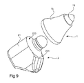
- Figs 1 and 2 illustrate a pick system, comprising a cutting bit 1 and a bit holder 2.
- the cutting bit has a cutting point 13, and at a second end 12, the cutting bit presents an axially extending recess 14, which is adapted for receiving a protrusion 22 forming part of the bit holder 2.
- a cutting bit body 15 may be formed of e.g. steel, carbide or any other hard material.
- the cutting point 13 may be formed of carbide with a wear layer of a super hard material, such as diamond, polycrystalline diamond or cubic boron nitride, or only of the super hard material.
- the bit holder 2 may comprise a holder body 21, which may be formed of steel and presenting a protrusion 22, which is adapted for receiving the cutting bit 1.
- the protrusion and the holder body may be formed in one piece.
- the bit holder is adapted to be connected to a drive body, such as a drum or a drill head, in a relatively permanent manner.
- the term "permanent" here does not exclude that the bit holder is removable from the drive body without destroying either of them.
- an axial distance D from a base surface 18 of the conical body to an innermost portion of the groove forming part of the locking device 19 may be less than or equal to half a total height G of the generally conical body, including the cutting point.
- a radius R of the convex surface portion may be greater than or equal to about 1 ⁇ 4 of a distance D from the base surface 18 of the conical body to an innermost portion of the groove forming part of the locking device 19.
- a radius R of the convex surface portion may be less than or equal to twice a distance D from a base surface 18 of conical body to an innermost portion of the groove forming part of the locking device 19.
- the bit holder may have a bit facing surface 223, which is defined as the surface of the bit holder, which coincides with an axial projection of the recess onto the bit holder.
- the bit facing surface is generally annular.
- the bit facing surface faces the recess of the bit and may be positioned closer to the holder body than the locking means.
- a part of the bit facing surface may be concave to mate with the convex surface described above.
- At least a portion of the second end 12 of the bit may extend axially so far as to axially coincide entirely with the bit facing surface when the protruding part is completely received in the recess.
- the second end 12 extends so far as to coincide entirely with the bit facing surface over an annular segment of the bit facing surface when the protruding part is completely received in the recess.
- the second end 12 may also extend axially beyond the bit facing surface, either entirely or over an annular segment of the bit facing surface when the protruding part is completely received in the recess.
- the base surface 18 may be substantially annular and continuous, i.e. free from axial slits.
- Figs 3a-3b and 6 illustrate a first embodiment of a cutting bit 1 and a bit holder 2.
- the cutting bit 1 has a generally conical, or frusto-conical body 15, the envelope surface of which having a convex surface portion 16, or being substantially convex in its entirety.
- the body 15 may be substantially symmetrical.
- the cutting bit 1 presents a recess 14 starting at a base surface 18 and extending axially into the body 15 and ending at a recess bottom 141, which in this embodiment is substantially hemispherical.
- a locking device 19 is positioned in the recess 14.
- the locking device 19 may comprise a circumferential groove, in which a locking ring may be arranged.
- the locking ring may be resilient. Its periphery may be continuous or discontinuous, e.g. crenellated.
- the locking device may be designed to provide a sufficient gap to allow a rotational movement between the bit and the bit holder once the locking device has been activated to connect a bit 1 to a bit holder 2.
- the locking device may comprise at least one part arranged on the cutting bit and one part arranged on the bit holder.
- the locking means may comprise one or more locking protrusions, which are to be received in a complementary locking recess.
- the locking protrusion may be formed in one piece with either the cutting bit or the bit holder, or they may be provided in the form of a separate part, which is initially mounted on the bit holder or in the cutting bit.
- transition surface 17 which may present a convex surface portion (as seen in cross section), or which may be convex in its entirety.
- the bit holder may have a shape which is complementary to that of the recess 14, with a small gap allowing for relative rotational movement between the bit and the bit holder.
- the protrusion may have a substantially hemispherical distal end 222, a locking device, which may be formed as a circumferential groove, and a transition surface 221, adapted for interaction with the transition surface 17, and thus presenting a generally concave surface portion extending from the locking device.
- Figs 4a-4b and 7 illustrate a second embodiment of a cutting bit 1' and a bit holder 2'.
- the cutting bit 1' has a generally conical, or frusto-conical body 15', the envelope surface of which having a convex surface portion 16, or being substantially convex in its entirety.
- the body 15' may be substantially symmetrical.
- the cutting bit 1' presents a recess 14 starting at a base surface 18 and extending axially into the body 15' and ending at a recess bottom 141', which in this embodiment is substantially flat with chamfered edges.
- a locking device 19 is positioned in the recess 14.
- the locking device 19 may comprise a circumferential groove, in which a locking ring may be arranged.
- the locking ring may be resilient.
- transition surface 17 which may present a convex surface portion (as seen in cross section), or which may be convex in its entirety.
- the bit holder 2' may have a shape which is complementary to that of the recess 14, with a small gap allowing for relative rotational movement between the bit and the bit holder.
- the protrusion may have a substantially flat distal end 222', with chamfered edges; a locking device, which may be formed as a circumferential groove, and a transition surface 221, adapted for interaction with the transition surface 17, and thus presenting a generally concave surface portion extending from the locking device.
- Figs 5a-5b and 8 illustrate a third embodiment of a cutting bit 1"and a bit holder 2'.
- the cutting bit 1" has a generally conical, or frusto-conical body 15', the envelope surface of which having a convex surface portion 16, or being substantially convex in its entirety.
- the body 15' may be substantially symmetrical.
- the cutting bit 1 presents a recess 14 starting at a base surface 18 and extending axially into the body 15' and ending at a recess bottom 141", which in this embodiment is substantially flat with rounded edges.
- a locking device 19 is positioned in the recess 14.
- the locking device 19 may comprise a circumferential groove, in which a locking ring may be arranged.
- the locking ring may be resilient.
- One or more bearings 191, 192 which may be in the form of ball bearings, are provided between the locking device 19 and the base surface 18.
- transition surface 17 which may present a convex surface portion (as seen in cross section), or which may be convex in its entirety.
- the convex transition surface may, as an alternative, originate at the lowermost bearing 192 and extend towards, or all the way to, the base surface 18.
- the bearings 191, 192 may comprise a plurality of balls and a ball holder, as is conventional in ball bearing technology.
- the bearing or bearings 191, 192 may be provided in addition to, or instead of, the locking device 19.
- the bit holder 2' may have a shape which is complementary to that of the recess 14, with a small gap allowing for relative rotational movement between the bit and the bit holder.
- the protrusion may have a substantially flat distal end 222', with rounded edges; a locking device, which may be formed as a circumferential groove, and a transition surface 221, adapted for interaction with the transition surface 17, and thus presenting a generally concave surface portion extending from the locking device.
- the protrusion 22' may further have one or more bearing grooves adapted for receiving the bearings arranged in the recess 14' of the bit 1".
- the holder may present a bit facing surface 223, 224, comprising one part 223 which may be conical for interaction with the conical surface of the entrance portion of the bit recess 14 and one part 224 which may be generally flat.
- bit holder 2', 2' presents only the conical surface 223, and no such generally flat part.
- annular grooves are provided on protruding part 22 of the bit holder and in the recess 14 of the cutting bit.
- other locking device arrangements are not excluded.
- bearings may be connected to the recess 14' of the bit or to the protrusion 22'.
- An advantage of connecting the bearings to the recess 14' would be that they are replaced every time the bit 1" is replaced.
- An advantage of connecting the bearings to the protrusion 22' is that they would then be reused, thus reducing the complexity and cost of the bit 1".
- the bearing or bearings may form part of, or entirely constitute, the locking device.
- the cutting bit at its second end 12 with a skirt (not shown) extending axially from the base surface 18 and enclosing at least part of the holder, thereby providing additional protection of the holder and in particular the holder's interface with the cutting bit.
- the skirt may be formed in one piece with the bit or by a separate part which is attached to the bit body, and it may extend all the way around the recess 14. There may be a radial gap between an innermost surface of the skirt and the holder.
- the skirt may be designed not to participate in the transfer of forces from the bit to the bit holder.
Landscapes
- Engineering & Computer Science (AREA)
- Mining & Mineral Resources (AREA)
- Mechanical Engineering (AREA)
- Life Sciences & Earth Sciences (AREA)
- General Life Sciences & Earth Sciences (AREA)
- Geochemistry & Mineralogy (AREA)
- Geology (AREA)
- Drilling And Exploitation, And Mining Machines And Methods (AREA)
- Earth Drilling (AREA)
Priority Applications (6)
| Application Number | Priority Date | Filing Date | Title |
|---|---|---|---|
| EP11163236.0A EP2514918B1 (fr) | 2011-04-20 | 2011-04-20 | Trépan tranchant et porte-pointes |
| CN201280019526.3A CN103492673B (zh) | 2011-04-20 | 2012-02-20 | 切割头和切割头保持器 |
| PCT/EP2012/052859 WO2012143153A2 (fr) | 2011-04-20 | 2012-02-20 | Outil de coupe et porte-outil |
| AU2012244559A AU2012244559B2 (en) | 2011-04-20 | 2012-02-20 | Cutting bit and bit holder |
| US14/112,639 US8960810B2 (en) | 2011-04-20 | 2012-02-20 | Cutting bit and bit holder |
| ZA2013/07646A ZA201307646B (en) | 2011-04-20 | 2013-10-14 | Cutting bit and bit holder |
Applications Claiming Priority (1)
| Application Number | Priority Date | Filing Date | Title |
|---|---|---|---|
| EP11163236.0A EP2514918B1 (fr) | 2011-04-20 | 2011-04-20 | Trépan tranchant et porte-pointes |
Publications (2)
| Publication Number | Publication Date |
|---|---|
| EP2514918A1 true EP2514918A1 (fr) | 2012-10-24 |
| EP2514918B1 EP2514918B1 (fr) | 2015-07-29 |
Family
ID=44484068
Family Applications (1)
| Application Number | Title | Priority Date | Filing Date |
|---|---|---|---|
| EP11163236.0A Not-in-force EP2514918B1 (fr) | 2011-04-20 | 2011-04-20 | Trépan tranchant et porte-pointes |
Country Status (6)
| Country | Link |
|---|---|
| US (1) | US8960810B2 (fr) |
| EP (1) | EP2514918B1 (fr) |
| CN (1) | CN103492673B (fr) |
| AU (1) | AU2012244559B2 (fr) |
| WO (1) | WO2012143153A2 (fr) |
| ZA (1) | ZA201307646B (fr) |
Cited By (3)
| Publication number | Priority date | Publication date | Assignee | Title |
|---|---|---|---|---|
| EP2845997A1 (fr) | 2013-09-06 | 2015-03-11 | Sandvik Intellectual Property AB | Ensemble de retenue de trépan tranchant |
| US20150076894A1 (en) * | 2013-09-19 | 2015-03-19 | Sandvik Intellectual Property Ab | Cutting bit and bit assembly |
| EP2963237A1 (fr) | 2014-07-03 | 2016-01-06 | Sandvik Intellectual Property AB | Ensemble de retenue de trépan de coupe à angle variable |
Families Citing this family (7)
| Publication number | Priority date | Publication date | Assignee | Title |
|---|---|---|---|---|
| CN104394899B (zh) | 2012-12-20 | 2017-04-05 | 甘布罗伦迪亚股份公司 | 血液套件组件连接检测 |
| US10465512B2 (en) | 2017-02-28 | 2019-11-05 | Kennametal Inc. | Rotatable cutting tool |
| US10640934B2 (en) * | 2017-11-13 | 2020-05-05 | Caterpillar Paving Products Inc. | Reclaiming drum having interchangeable rectangular and V-shaped paddles |
| CN108825227B (zh) * | 2018-08-08 | 2024-08-09 | 徐州徐工基础工程机械有限公司 | 掘进机切割装置和掘进机 |
| AU2019387712B2 (en) * | 2018-11-26 | 2025-12-11 | Ulterra Drilling Technologies, L.P. | Drill bit for boring earth and other hard materials |
| USD909165S1 (en) | 2019-08-27 | 2021-02-02 | Kennametal Inc | Adapter block |
| US10934840B1 (en) | 2019-08-27 | 2021-03-02 | Kennametal Inc. | Self-aligning adapter block |
Citations (6)
| Publication number | Priority date | Publication date | Assignee | Title |
|---|---|---|---|---|
| US3342531A (en) | 1965-02-16 | 1967-09-19 | Cincinnati Mine Machinery Co | Conical cutter bits held by resilient retainer for free rotation |
| US3932952A (en) * | 1973-12-17 | 1976-01-20 | Caterpillar Tractor Co. | Multi-material ripper tip |
| US5261499A (en) | 1992-07-15 | 1993-11-16 | Kennametal Inc. | Two-piece rotatable cutting bit |
| EP0819208A1 (fr) * | 1995-04-06 | 1998-01-21 | Kennametal South Africa (Proprietary) Limited | Extraction d'un porte-pic |
| US20080258536A1 (en) | 2006-08-11 | 2008-10-23 | Hall David R | High-impact Resistant Tool |
| US20080309148A1 (en) | 2006-08-11 | 2008-12-18 | Hall David R | Degradation Assembly Shield |
Family Cites Families (8)
| Publication number | Priority date | Publication date | Assignee | Title |
|---|---|---|---|---|
| US3331637A (en) * | 1965-05-07 | 1967-07-18 | Cincinnati Mine Machinery Co | Cutter bits and mounting means therefor |
| DE7532482U (de) * | 1975-10-11 | 1976-02-19 | Ugine Carbone, Grenoble (Frankreich) | Drehmeissel |
| GB1568992A (en) * | 1977-03-28 | 1980-06-11 | Hoy & Co Ltd Austin | Assembly for holding mineral cutter picks |
| US4299424A (en) * | 1979-12-03 | 1981-11-10 | National Mine Service Company | Cutting tool assembly |
| US4911504A (en) * | 1988-07-20 | 1990-03-27 | Kennametal Inc. | Cutter bit and tip |
| US20100244545A1 (en) * | 2006-06-16 | 2010-09-30 | Hall David R | Shearing Cutter on a Degradation Drum |
| CN201025036Y (zh) * | 2007-04-27 | 2008-02-20 | 桂林电子科技大学 | 可重复使用截齿体的镐形截齿 |
| US8322796B2 (en) * | 2009-04-16 | 2012-12-04 | Schlumberger Technology Corporation | Seal with contact element for pick shield |
-
2011
- 2011-04-20 EP EP11163236.0A patent/EP2514918B1/fr not_active Not-in-force
-
2012
- 2012-02-20 AU AU2012244559A patent/AU2012244559B2/en not_active Ceased
- 2012-02-20 CN CN201280019526.3A patent/CN103492673B/zh not_active Expired - Fee Related
- 2012-02-20 WO PCT/EP2012/052859 patent/WO2012143153A2/fr not_active Ceased
- 2012-02-20 US US14/112,639 patent/US8960810B2/en not_active Expired - Fee Related
-
2013
- 2013-10-14 ZA ZA2013/07646A patent/ZA201307646B/en unknown
Patent Citations (6)
| Publication number | Priority date | Publication date | Assignee | Title |
|---|---|---|---|---|
| US3342531A (en) | 1965-02-16 | 1967-09-19 | Cincinnati Mine Machinery Co | Conical cutter bits held by resilient retainer for free rotation |
| US3932952A (en) * | 1973-12-17 | 1976-01-20 | Caterpillar Tractor Co. | Multi-material ripper tip |
| US5261499A (en) | 1992-07-15 | 1993-11-16 | Kennametal Inc. | Two-piece rotatable cutting bit |
| EP0819208A1 (fr) * | 1995-04-06 | 1998-01-21 | Kennametal South Africa (Proprietary) Limited | Extraction d'un porte-pic |
| US20080258536A1 (en) | 2006-08-11 | 2008-10-23 | Hall David R | High-impact Resistant Tool |
| US20080309148A1 (en) | 2006-08-11 | 2008-12-18 | Hall David R | Degradation Assembly Shield |
Cited By (5)
| Publication number | Priority date | Publication date | Assignee | Title |
|---|---|---|---|---|
| EP2845997A1 (fr) | 2013-09-06 | 2015-03-11 | Sandvik Intellectual Property AB | Ensemble de retenue de trépan tranchant |
| US20150076894A1 (en) * | 2013-09-19 | 2015-03-19 | Sandvik Intellectual Property Ab | Cutting bit and bit assembly |
| EP2851507A1 (fr) | 2013-09-19 | 2015-03-25 | Sandvik Intellectual Property AB | Trépan tranchant et ensemble trépan |
| US9359894B2 (en) | 2013-09-19 | 2016-06-07 | Sandvik Intellectual Property Ab | Cutting bit and bit assembly |
| EP2963237A1 (fr) | 2014-07-03 | 2016-01-06 | Sandvik Intellectual Property AB | Ensemble de retenue de trépan de coupe à angle variable |
Also Published As
| Publication number | Publication date |
|---|---|
| WO2012143153A2 (fr) | 2012-10-26 |
| EP2514918B1 (fr) | 2015-07-29 |
| CN103492673B (zh) | 2016-09-21 |
| AU2012244559A1 (en) | 2013-10-31 |
| CN103492673A (zh) | 2014-01-01 |
| WO2012143153A3 (fr) | 2013-04-04 |
| US8960810B2 (en) | 2015-02-24 |
| ZA201307646B (en) | 2021-05-26 |
| US20140042795A1 (en) | 2014-02-13 |
| AU2012244559B2 (en) | 2017-04-20 |
Similar Documents
| Publication | Publication Date | Title |
|---|---|---|
| EP2514918B1 (fr) | Trépan tranchant et porte-pointes | |
| JP6127463B2 (ja) | 掘削工具 | |
| US20040004389A1 (en) | Replacable wear surface for bit support | |
| EP2812532B1 (fr) | Outil de piquage et ensemble comprenant celui-ci | |
| WO2014033227A2 (fr) | Ensemble pioche, ensemble trépan et outil de dégradation | |
| US9556733B2 (en) | Tunnel boring machine disc cutters and related methods of manufacture | |
| JP7474884B2 (ja) | ミーリングビット | |
| AU2017216588A1 (en) | Drill bit for rock drilling tool, and rock drilling tool | |
| CN101796263A (zh) | 牙轮钻具或牙轮钻头 | |
| EP2921639A1 (fr) | Trépan à percussion avec de multiples ensembles d'inserts de coupe avant | |
| CA2172457C (fr) | Tete de tariere, creuse | |
| US12247486B2 (en) | Bolsters for degradation picks | |
| JP2016135983A (ja) | 掘削チップおよび掘削ビット |
Legal Events
| Date | Code | Title | Description |
|---|---|---|---|
| PUAI | Public reference made under article 153(3) epc to a published international application that has entered the european phase |
Free format text: ORIGINAL CODE: 0009012 |
|
| 17P | Request for examination filed |
Effective date: 20110420 |
|
| AK | Designated contracting states |
Kind code of ref document: A1 Designated state(s): AL AT BE BG CH CY CZ DE DK EE ES FI FR GB GR HR HU IE IS IT LI LT LU LV MC MK MT NL NO PL PT RO RS SE SI SK SM TR |
|
| AX | Request for extension of the european patent |
Extension state: BA ME |
|
| GRAP | Despatch of communication of intention to grant a patent |
Free format text: ORIGINAL CODE: EPIDOSNIGR1 |
|
| INTG | Intention to grant announced |
Effective date: 20150407 |
|
| GRAS | Grant fee paid |
Free format text: ORIGINAL CODE: EPIDOSNIGR3 |
|
| GRAA | (expected) grant |
Free format text: ORIGINAL CODE: 0009210 |
|
| AK | Designated contracting states |
Kind code of ref document: B1 Designated state(s): AL AT BE BG CH CY CZ DE DK EE ES FI FR GB GR HR HU IE IS IT LI LT LU LV MC MK MT NL NO PL PT RO RS SE SI SK SM TR |
|
| REG | Reference to a national code |
Ref country code: GB Ref legal event code: FG4D |
|
| REG | Reference to a national code |
Ref country code: CH Ref legal event code: EP |
|
| REG | Reference to a national code |
Ref country code: AT Ref legal event code: REF Ref document number: 739465 Country of ref document: AT Kind code of ref document: T Effective date: 20150815 |
|
| REG | Reference to a national code |
Ref country code: IE Ref legal event code: FG4D |
|
| REG | Reference to a national code |
Ref country code: DE Ref legal event code: R096 Ref document number: 602011018158 Country of ref document: DE |
|
| REG | Reference to a national code |
Ref country code: AT Ref legal event code: MK05 Ref document number: 739465 Country of ref document: AT Kind code of ref document: T Effective date: 20150729 |
|
| REG | Reference to a national code |
Ref country code: LT Ref legal event code: MG4D |
|
| REG | Reference to a national code |
Ref country code: NL Ref legal event code: MP Effective date: 20150729 |
|
| PG25 | Lapsed in a contracting state [announced via postgrant information from national office to epo] |
Ref country code: FI Free format text: LAPSE BECAUSE OF FAILURE TO SUBMIT A TRANSLATION OF THE DESCRIPTION OR TO PAY THE FEE WITHIN THE PRESCRIBED TIME-LIMIT Effective date: 20150729 Ref country code: NO Free format text: LAPSE BECAUSE OF FAILURE TO SUBMIT A TRANSLATION OF THE DESCRIPTION OR TO PAY THE FEE WITHIN THE PRESCRIBED TIME-LIMIT Effective date: 20151029 Ref country code: LT Free format text: LAPSE BECAUSE OF FAILURE TO SUBMIT A TRANSLATION OF THE DESCRIPTION OR TO PAY THE FEE WITHIN THE PRESCRIBED TIME-LIMIT Effective date: 20150729 Ref country code: LV Free format text: LAPSE BECAUSE OF FAILURE TO SUBMIT A TRANSLATION OF THE DESCRIPTION OR TO PAY THE FEE WITHIN THE PRESCRIBED TIME-LIMIT Effective date: 20150729 Ref country code: GR Free format text: LAPSE BECAUSE OF FAILURE TO SUBMIT A TRANSLATION OF THE DESCRIPTION OR TO PAY THE FEE WITHIN THE PRESCRIBED TIME-LIMIT Effective date: 20151030 |
|
| PG25 | Lapsed in a contracting state [announced via postgrant information from national office to epo] |
Ref country code: SE Free format text: LAPSE BECAUSE OF FAILURE TO SUBMIT A TRANSLATION OF THE DESCRIPTION OR TO PAY THE FEE WITHIN THE PRESCRIBED TIME-LIMIT Effective date: 20150729 Ref country code: ES Free format text: LAPSE BECAUSE OF FAILURE TO SUBMIT A TRANSLATION OF THE DESCRIPTION OR TO PAY THE FEE WITHIN THE PRESCRIBED TIME-LIMIT Effective date: 20150729 Ref country code: PT Free format text: LAPSE BECAUSE OF FAILURE TO SUBMIT A TRANSLATION OF THE DESCRIPTION OR TO PAY THE FEE WITHIN THE PRESCRIBED TIME-LIMIT Effective date: 20151130 Ref country code: IS Free format text: LAPSE BECAUSE OF FAILURE TO SUBMIT A TRANSLATION OF THE DESCRIPTION OR TO PAY THE FEE WITHIN THE PRESCRIBED TIME-LIMIT Effective date: 20151129 Ref country code: AT Free format text: LAPSE BECAUSE OF FAILURE TO SUBMIT A TRANSLATION OF THE DESCRIPTION OR TO PAY THE FEE WITHIN THE PRESCRIBED TIME-LIMIT Effective date: 20150729 Ref country code: PL Free format text: LAPSE BECAUSE OF FAILURE TO SUBMIT A TRANSLATION OF THE DESCRIPTION OR TO PAY THE FEE WITHIN THE PRESCRIBED TIME-LIMIT Effective date: 20150729 Ref country code: HR Free format text: LAPSE BECAUSE OF FAILURE TO SUBMIT A TRANSLATION OF THE DESCRIPTION OR TO PAY THE FEE WITHIN THE PRESCRIBED TIME-LIMIT Effective date: 20150729 Ref country code: RS Free format text: LAPSE BECAUSE OF FAILURE TO SUBMIT A TRANSLATION OF THE DESCRIPTION OR TO PAY THE FEE WITHIN THE PRESCRIBED TIME-LIMIT Effective date: 20150729 |
|
| PG25 | Lapsed in a contracting state [announced via postgrant information from national office to epo] |
Ref country code: NL Free format text: LAPSE BECAUSE OF FAILURE TO SUBMIT A TRANSLATION OF THE DESCRIPTION OR TO PAY THE FEE WITHIN THE PRESCRIBED TIME-LIMIT Effective date: 20150729 |
|
| PG25 | Lapsed in a contracting state [announced via postgrant information from national office to epo] |
Ref country code: EE Free format text: LAPSE BECAUSE OF FAILURE TO SUBMIT A TRANSLATION OF THE DESCRIPTION OR TO PAY THE FEE WITHIN THE PRESCRIBED TIME-LIMIT Effective date: 20150729 Ref country code: DK Free format text: LAPSE BECAUSE OF FAILURE TO SUBMIT A TRANSLATION OF THE DESCRIPTION OR TO PAY THE FEE WITHIN THE PRESCRIBED TIME-LIMIT Effective date: 20150729 Ref country code: IT Free format text: LAPSE BECAUSE OF FAILURE TO SUBMIT A TRANSLATION OF THE DESCRIPTION OR TO PAY THE FEE WITHIN THE PRESCRIBED TIME-LIMIT Effective date: 20150729 Ref country code: CZ Free format text: LAPSE BECAUSE OF FAILURE TO SUBMIT A TRANSLATION OF THE DESCRIPTION OR TO PAY THE FEE WITHIN THE PRESCRIBED TIME-LIMIT Effective date: 20150729 Ref country code: SK Free format text: LAPSE BECAUSE OF FAILURE TO SUBMIT A TRANSLATION OF THE DESCRIPTION OR TO PAY THE FEE WITHIN THE PRESCRIBED TIME-LIMIT Effective date: 20150729 |
|
| REG | Reference to a national code |
Ref country code: DE Ref legal event code: R097 Ref document number: 602011018158 Country of ref document: DE |
|
| PG25 | Lapsed in a contracting state [announced via postgrant information from national office to epo] |
Ref country code: RO Free format text: LAPSE BECAUSE OF FAILURE TO SUBMIT A TRANSLATION OF THE DESCRIPTION OR TO PAY THE FEE WITHIN THE PRESCRIBED TIME-LIMIT Effective date: 20150729 |
|
| PLBE | No opposition filed within time limit |
Free format text: ORIGINAL CODE: 0009261 |
|
| STAA | Information on the status of an ep patent application or granted ep patent |
Free format text: STATUS: NO OPPOSITION FILED WITHIN TIME LIMIT |
|
| 26N | No opposition filed |
Effective date: 20160502 |
|
| PG25 | Lapsed in a contracting state [announced via postgrant information from national office to epo] |
Ref country code: SI Free format text: LAPSE BECAUSE OF FAILURE TO SUBMIT A TRANSLATION OF THE DESCRIPTION OR TO PAY THE FEE WITHIN THE PRESCRIBED TIME-LIMIT Effective date: 20150729 Ref country code: BE Free format text: LAPSE BECAUSE OF NON-PAYMENT OF DUE FEES Effective date: 20160430 |
|
| REG | Reference to a national code |
Ref country code: CH Ref legal event code: PL |
|
| GBPC | Gb: european patent ceased through non-payment of renewal fee |
Effective date: 20160420 |
|
| PG25 | Lapsed in a contracting state [announced via postgrant information from national office to epo] |
Ref country code: BE Free format text: LAPSE BECAUSE OF FAILURE TO SUBMIT A TRANSLATION OF THE DESCRIPTION OR TO PAY THE FEE WITHIN THE PRESCRIBED TIME-LIMIT Effective date: 20150729 Ref country code: LU Free format text: LAPSE BECAUSE OF FAILURE TO SUBMIT A TRANSLATION OF THE DESCRIPTION OR TO PAY THE FEE WITHIN THE PRESCRIBED TIME-LIMIT Effective date: 20160420 |
|
| REG | Reference to a national code |
Ref country code: IE Ref legal event code: MM4A |
|
| REG | Reference to a national code |
Ref country code: FR Ref legal event code: ST Effective date: 20161230 |
|
| PG25 | Lapsed in a contracting state [announced via postgrant information from national office to epo] |
Ref country code: FR Free format text: LAPSE BECAUSE OF NON-PAYMENT OF DUE FEES Effective date: 20160502 Ref country code: GB Free format text: LAPSE BECAUSE OF NON-PAYMENT OF DUE FEES Effective date: 20160420 Ref country code: LI Free format text: LAPSE BECAUSE OF NON-PAYMENT OF DUE FEES Effective date: 20160430 Ref country code: CH Free format text: LAPSE BECAUSE OF NON-PAYMENT OF DUE FEES Effective date: 20160430 |
|
| PG25 | Lapsed in a contracting state [announced via postgrant information from national office to epo] |
Ref country code: IE Free format text: LAPSE BECAUSE OF NON-PAYMENT OF DUE FEES Effective date: 20160420 |
|
| PG25 | Lapsed in a contracting state [announced via postgrant information from national office to epo] |
Ref country code: SM Free format text: LAPSE BECAUSE OF FAILURE TO SUBMIT A TRANSLATION OF THE DESCRIPTION OR TO PAY THE FEE WITHIN THE PRESCRIBED TIME-LIMIT Effective date: 20150729 Ref country code: CY Free format text: LAPSE BECAUSE OF FAILURE TO SUBMIT A TRANSLATION OF THE DESCRIPTION OR TO PAY THE FEE WITHIN THE PRESCRIBED TIME-LIMIT Effective date: 20150729 Ref country code: HU Free format text: LAPSE BECAUSE OF FAILURE TO SUBMIT A TRANSLATION OF THE DESCRIPTION OR TO PAY THE FEE WITHIN THE PRESCRIBED TIME-LIMIT; INVALID AB INITIO Effective date: 20110420 |
|
| PG25 | Lapsed in a contracting state [announced via postgrant information from national office to epo] |
Ref country code: TR Free format text: LAPSE BECAUSE OF FAILURE TO SUBMIT A TRANSLATION OF THE DESCRIPTION OR TO PAY THE FEE WITHIN THE PRESCRIBED TIME-LIMIT Effective date: 20150729 Ref country code: MK Free format text: LAPSE BECAUSE OF FAILURE TO SUBMIT A TRANSLATION OF THE DESCRIPTION OR TO PAY THE FEE WITHIN THE PRESCRIBED TIME-LIMIT Effective date: 20150729 Ref country code: MT Free format text: LAPSE BECAUSE OF NON-PAYMENT OF DUE FEES Effective date: 20160430 Ref country code: MC Free format text: LAPSE BECAUSE OF FAILURE TO SUBMIT A TRANSLATION OF THE DESCRIPTION OR TO PAY THE FEE WITHIN THE PRESCRIBED TIME-LIMIT Effective date: 20150729 |
|
| PG25 | Lapsed in a contracting state [announced via postgrant information from national office to epo] |
Ref country code: BG Free format text: LAPSE BECAUSE OF FAILURE TO SUBMIT A TRANSLATION OF THE DESCRIPTION OR TO PAY THE FEE WITHIN THE PRESCRIBED TIME-LIMIT Effective date: 20150729 |
|
| PG25 | Lapsed in a contracting state [announced via postgrant information from national office to epo] |
Ref country code: AL Free format text: LAPSE BECAUSE OF FAILURE TO SUBMIT A TRANSLATION OF THE DESCRIPTION OR TO PAY THE FEE WITHIN THE PRESCRIBED TIME-LIMIT Effective date: 20150729 |
|
| PGFP | Annual fee paid to national office [announced via postgrant information from national office to epo] |
Ref country code: DE Payment date: 20210323 Year of fee payment: 11 |
|
| REG | Reference to a national code |
Ref country code: DE Ref legal event code: R119 Ref document number: 602011018158 Country of ref document: DE |
|
| PG25 | Lapsed in a contracting state [announced via postgrant information from national office to epo] |
Ref country code: DE Free format text: LAPSE BECAUSE OF NON-PAYMENT OF DUE FEES Effective date: 20221103 |