EP2514924A2 - Système et procédé de modification d'une encoche de rotor - Google Patents
Système et procédé de modification d'une encoche de rotor Download PDFInfo
- Publication number
- EP2514924A2 EP2514924A2 EP12164333A EP12164333A EP2514924A2 EP 2514924 A2 EP2514924 A2 EP 2514924A2 EP 12164333 A EP12164333 A EP 12164333A EP 12164333 A EP12164333 A EP 12164333A EP 2514924 A2 EP2514924 A2 EP 2514924A2
- Authority
- EP
- European Patent Office
- Prior art keywords
- slot
- drill
- rotor
- clamp
- vertical axis
- Prior art date
- Legal status (The legal status is an assumption and is not a legal conclusion. Google has not performed a legal analysis and makes no representation as to the accuracy of the status listed.)
- Withdrawn
Links
- 238000000034 method Methods 0.000 title claims abstract description 16
- 238000012986 modification Methods 0.000 description 10
- 230000004048 modification Effects 0.000 description 10
- 239000003570 air Substances 0.000 description 3
- 230000008901 benefit Effects 0.000 description 3
- 239000000567 combustion gas Substances 0.000 description 3
- 230000000295 complement effect Effects 0.000 description 3
- 239000012530 fluid Substances 0.000 description 3
- 238000005516 engineering process Methods 0.000 description 2
- 239000007789 gas Substances 0.000 description 2
- 238000005259 measurement Methods 0.000 description 2
- 239000012080 ambient air Substances 0.000 description 1
- 235000015895 biscuits Nutrition 0.000 description 1
- 230000005611 electricity Effects 0.000 description 1
- 239000000446 fuel Substances 0.000 description 1
- 230000006870 function Effects 0.000 description 1
- 238000003780 insertion Methods 0.000 description 1
- 230000037431 insertion Effects 0.000 description 1
- 238000007689 inspection Methods 0.000 description 1
- 238000009434 installation Methods 0.000 description 1
- 238000012423 maintenance Methods 0.000 description 1
- 238000012552 review Methods 0.000 description 1
Images




Classifications
-
- F—MECHANICAL ENGINEERING; LIGHTING; HEATING; WEAPONS; BLASTING
- F01—MACHINES OR ENGINES IN GENERAL; ENGINE PLANTS IN GENERAL; STEAM ENGINES
- F01D—NON-POSITIVE DISPLACEMENT MACHINES OR ENGINES, e.g. STEAM TURBINES
- F01D5/00—Blades; Blade-carrying members; Heating, heat-insulating, cooling or antivibration means on the blades or the members
- F01D5/005—Repairing methods or devices
-
- F—MECHANICAL ENGINEERING; LIGHTING; HEATING; WEAPONS; BLASTING
- F01—MACHINES OR ENGINES IN GENERAL; ENGINE PLANTS IN GENERAL; STEAM ENGINES
- F01D—NON-POSITIVE DISPLACEMENT MACHINES OR ENGINES, e.g. STEAM TURBINES
- F01D5/00—Blades; Blade-carrying members; Heating, heat-insulating, cooling or antivibration means on the blades or the members
- F01D5/30—Fixing blades to rotors; Blade roots ; Blade spacers
- F01D5/3007—Fixing blades to rotors; Blade roots ; Blade spacers of axial insertion type
-
- F—MECHANICAL ENGINEERING; LIGHTING; HEATING; WEAPONS; BLASTING
- F05—INDEXING SCHEMES RELATING TO ENGINES OR PUMPS IN VARIOUS SUBCLASSES OF CLASSES F01-F04
- F05D—INDEXING SCHEME FOR ASPECTS RELATING TO NON-POSITIVE-DISPLACEMENT MACHINES OR ENGINES, GAS-TURBINES OR JET-PROPULSION PLANTS
- F05D2230/00—Manufacture
- F05D2230/10—Manufacture by removing material
-
- F—MECHANICAL ENGINEERING; LIGHTING; HEATING; WEAPONS; BLASTING
- F05—INDEXING SCHEMES RELATING TO ENGINES OR PUMPS IN VARIOUS SUBCLASSES OF CLASSES F01-F04
- F05D—INDEXING SCHEME FOR ASPECTS RELATING TO NON-POSITIVE-DISPLACEMENT MACHINES OR ENGINES, GAS-TURBINES OR JET-PROPULSION PLANTS
- F05D2230/00—Manufacture
- F05D2230/80—Repairing, retrofitting or upgrading methods
-
- Y—GENERAL TAGGING OF NEW TECHNOLOGICAL DEVELOPMENTS; GENERAL TAGGING OF CROSS-SECTIONAL TECHNOLOGIES SPANNING OVER SEVERAL SECTIONS OF THE IPC; TECHNICAL SUBJECTS COVERED BY FORMER USPC CROSS-REFERENCE ART COLLECTIONS [XRACs] AND DIGESTS
- Y10—TECHNICAL SUBJECTS COVERED BY FORMER USPC
- Y10T—TECHNICAL SUBJECTS COVERED BY FORMER US CLASSIFICATION
- Y10T29/00—Metal working
- Y10T29/49—Method of mechanical manufacture
- Y10T29/49716—Converting
-
- Y—GENERAL TAGGING OF NEW TECHNOLOGICAL DEVELOPMENTS; GENERAL TAGGING OF CROSS-SECTIONAL TECHNOLOGIES SPANNING OVER SEVERAL SECTIONS OF THE IPC; TECHNICAL SUBJECTS COVERED BY FORMER USPC CROSS-REFERENCE ART COLLECTIONS [XRACs] AND DIGESTS
- Y10—TECHNICAL SUBJECTS COVERED BY FORMER USPC
- Y10T—TECHNICAL SUBJECTS COVERED BY FORMER US CLASSIFICATION
- Y10T408/00—Cutting by use of rotating axially moving tool
- Y10T408/55—Cutting by use of rotating axially moving tool with work-engaging structure other than Tool or tool-support
- Y10T408/563—Work-gripping clamp
-
- Y—GENERAL TAGGING OF NEW TECHNOLOGICAL DEVELOPMENTS; GENERAL TAGGING OF CROSS-SECTIONAL TECHNOLOGIES SPANNING OVER SEVERAL SECTIONS OF THE IPC; TECHNICAL SUBJECTS COVERED BY FORMER USPC CROSS-REFERENCE ART COLLECTIONS [XRACs] AND DIGESTS
- Y10—TECHNICAL SUBJECTS COVERED BY FORMER USPC
- Y10T—TECHNICAL SUBJECTS COVERED BY FORMER US CLASSIFICATION
- Y10T408/00—Cutting by use of rotating axially moving tool
- Y10T408/65—Means to drive tool
- Y10T408/675—Means to drive tool including means to move Tool along tool-axis
- Y10T408/6764—Laterally adjustable Tool
Definitions
- the present invention generally involves a system and method for modifying a rotor.
- embodiments of the present invention provide a system and method for creating a cavity in a slot in the rotor.
- a typical gas turbine includes an axial compressor at the front, one or more combustors around the middle, and a turbine at the rear.
- the compressor generally includes a casing that surrounds and encloses alternating stages of circumferentially mounted stator vanes and rotating blades.
- the stator vanes typically attach to the casing, and the rotating blades typically attach to a rotor inside the compressor.
- Ambient air enters the compressor, and each stage of stator vanes directs the airflow onto the following stage of rotating blades to progressively impart kinetic energy to the working fluid (air) to bring it to a highly energized state.
- the working fluid exits the compressor and flows to the combustors where it mixes with fuel and ignites to generate combustion gases having a high temperature and pressure.
- the combustion gases exit the combustors and flow to the turbine where they expand to produce work. For example, expansion of the combustion gases in the turbine may rotate a shaft connected to a generator to produce electricity.
- the rotating blades in the compressor typically connect to the rotor in a manner that allows the rotating blades to be periodically removed for maintenance, inspections, and/or replacement.
- the rotating blades may include a root or base that slides into a complementary dovetail slot in the rotor.
- the complementary surfaces between the root and the dovetail slot prevent each blade from moving radially, and the area on the rotor surrounding the slot may be "staked" or plastically deformed to prevent the root from moving axially in the slot.
- each rotating blade may be removed from the rotor, and the same or a replacement blade may be reinserted into the dovetail slot before the rotor is re-staked to hold the blade in place.
- the modification to the slot in the rotor typically requires substantial disassembly of the compressor and associated equipment to provide suitable access to the rotor.
- the casing surrounding the rotating blades is often completely removed, and scaffolding is erected around the rotor to support the equipment and personnel performing the modification.
- the gas turbine itself may be situated in a building having walls and/or a roof that must be removed or otherwise opened to provide sufficient access to the rotor.
- This disassembly and staging is expensive to perform, extends the time needed for the rotor modification, and increases the outage associated with the modification. Therefore, an improved system and method for modifying the slot in the rotor that reduces the amount of disassembly of the compressor and staging would be useful.
- the present invention resides in a system for modifying a slot in a rotor, including a base having a vertical axis, a drill slidingly connected to the base along the vertical axis, and a clamp is connected to the base and configured to engage with an interior surface of the slot.
- the system may further include a means for aligning the drill above the slot.
- the present invention also resides in a method for modifying a slot in a rotor, including locating a drill proximate to the slot and inserting a clamp into the slot, wherein the clamp is slidingly connected to the drill.
- the method further includes engaging the clamp with an interior surface of the slot and operating the drill to create a cavity in the slot.
- a drill may be mounted on the rotor in the radial space previously occupied by a removed blade, allowing the modification to be performed without requiring complete removal of a casing or any walls or other structures surrounding the rotor.
- the system may include means for moving, axially aligning, measuring movement, and/or limiting movement of the drill so that the modification may be precisely and repeatably performed in the confined space.
- Fig. 1 provides a cross sectional view of an exemplary compressor 10 to illustrate various embodiments of the present invention.
- the compressor 10 generally includes alternating stages of stator vanes 12 and rotating blades 14 as is known in the art.
- the first stage of stator vanes 12 is commonly referred to as the inlet guide vane and may be adjustable to vary the amount or volume of air flow through the compressor 10.
- Each stage of stator vanes 12 and rotating blades 14 generally comprises a plurality of circumferentially arranged airfoils, with the stator vanes 12 attached to a casing 16 surrounding the compressor 10 and the rotating blades 14 attached to a rotor 18 generally aligned with an axial centerline of the compressor 10.
- the stator vanes 12 direct the airflow entering the compressor 10 onto the following stage of rotating blades 14 to progressively impart kinetic energy to the working fluid (air) to bring it to a highly energized state.
- Fig. 2 provides an enlarged perspective view of a portion of a first stage of rotating blades 14 in the compressor 10.
- the rotating blades 14 extend radially from a rim 20 of the rotor 18.
- Each blade 14 generally includes a root 22 that slides into a slot 24 in the rim 20, and the complementary surfaces between the root 22 and the slot 24 prevent each blade 14 from moving radially.
- the rim 20 of the rotor 18 may be "staked" or plastically deformed, producing the characteristic stake marks 26 shown in Fig. 2 , to prevent the root 22 from moving axially in the slot 24.
- Fig. 3 provides an enlarged perspective view of the first stage of rotating blades 14 shown in Fig. 2 after being modified with an embodiment of the present invention.
- a portion of the rim 20 has been machined to form a cavity 28 in the slot 24.
- An insert 30 or biscuit has been placed in the cavity 28 and staked to axially restrain the root 22 in the slot 24.
- each rotating blade 14 may be repeatedly removed from the rotor 18, and a new insert 30 may be placed in the cavity 28 to stake the rotating blade 14 in place once reinstalled.
- Figs. 4-7 provide perspective, top, front, and side views, respectively, of a system 40 for modifying the rotor 18 according to an embodiment of the present invention.
- the system 40 generally comprises a drill 42 slidingly connected to a base 44 along a vertical axis 46.
- the drill 42 may comprise, for example, a pneumatic, hydraulic, or electric motor 48 connected by a gearbox 50 to a drill chuck 52 configured to retain a drill bit 54, as is known in the art. Cables 56 connected to the motor 48 may supply pneumatic, hydraulic, or electric power to operate the motor 48, and a controller 58 may allow an operator to remotely actuate the motor 48 as desired.
- One or more gears may provide a geared connection 60 between the drill 42 and the base 44 to provide a mechanical advantage for sliding the drill 42 along a rail 62 aligned with or parallel to the vertical axis 46.
- the number and orientation of gears and particular gear ratio achieved by the geared connection 60 may be easily determined by one of ordinary skill in the art without undue experimentation and is not a limitation of the present invention unless specifically recited in the claims.
- a handle 64 may be operably connected to the geared connection 60 so that rotation of the handle 64 causes the geared connection 60 to advance or retract the drill 42 along the rail 62, thus repositioning the drill 42 vertically with respect to the base 44.
- actuation of the motor 48 will drive the drill bit 54 to machine or bore the cavity 28 in the rotor 18, and the handle may be further rotated to advance or retract the drill bit 54 in the cavity 28.
- the system 40 may further include one or more components or devices that precisely position the drill 42 and/or base 44 with respect to the slot 24, that precisely measure movement of the drill 42 along the vertical axis 46, and/or that limit radial movement of the drill 42 along the vertical axis 46.
- the system 40 may include means for axially aligning the drill 42 and/or the base 44 with respect to the slot 24.
- the means for axially aligning the drill 42 and/or the base 44 with respect to the slot 24 may comprise, for example, one or more projections or alignment tabs 66 that extend radially from the drill 42 and/or base 44. In this manner, the one or more projections may contact with the front face of the rotor 18 to axially align the drill 42 and/or base 44 with respect to the slot 24.
- Other suitable structures for performing the function of axially aligning the drill 42 and/or base 44 with respect to the slot 24 may comprise one or more detents, measurement strips, straight edges, pins, or similar devices attached to the drill 42 and/or base 44.
- the system 40 may include means for measuring movement of the drill 42 along the vertical axis 46.
- the means for measuring movement of the drill 42 along the vertical axis 46 may comprise any sensor that measures radial movement of the drill 42 along the vertical axis 46.
- the means for measuring movement of the drill 42 along the vertical axis 46 may comprise a micrometer 68 connected to the drill 42 so that the micrometer 68 moves radially with the drill 42 as the drill 42 slides along the vertical axis 46.
- the micrometer 68 may include a retractable plunger 70 configured to contact a reference plate 72 so that the micrometer 68 may measure movement of the retractable plunger 70 as the drill 42 moves along the vertical axis 46.
- the micrometer 68 or other sensor may be connected to the base 44 or other stationary component with respect to the drill 42 to measure radial movement of the drill 42 along the vertical axis 46.
- the system 40 may include means for limiting movement of the drill 42 along the vertical axis 46.
- a mechanical stop 74 between the drill 42 and the base 44 physically limits vertical movement of the drill 42 with respect to the base 44 and thus along the vertical axis 46.
- the mechanical stop 74 may comprise, for example, a stud 76 in threaded engagement with the base 44 so that the height of the stud 76 relative to the base 44 may be adjusted.
- the mechanical stop 74 may further include a lock 78, such as a bolt, nut, or ring, configured to engage the stud 76 and prevent the stud 76 from inadvertent movement.
- Additional suitable structures for limiting movement of the drill 42 along the vertical axis 46 may include, for example a detent, notch, or other mechanical device located on the geared connection 60 and/or rail 62 that limits radial movement of the drill 42 along the vertical axis 46.
- the system 40 may further include means for aligning the drill 42, base 44, and/or vertical axis 46 above or radially outward from the slot 24.
- the means for aligning the drill 42, base 44, and/or vertical axis 46 above the slot 24 comprises a clamp 80 slidingly connected to the drill 42 and/or base 44 and that fits inside the slot 24.
- An outer perimeter 82 of the clamp 80 may approximately conform to the interior surface of the slot 24 so that when the clamp 80 is axially slid into the slot 24, at least a portion of the clamp 80 engages with the interior surface of the slot 24 to hold the drill 42, base 44, and/or vertical axis 46 above the slot 24.
- the clamp 80 may additionally include, for example, one or more projections 84 in threaded engagement with a set screw 86. Rotation of the set screw 86 may force the one or more projections 84 against an inclined surface 88 inside the clamp 80 to extend the projections 84 beyond the outer perimeter 82 of the clamp 80 to further bind the clamp 80 to the slot 24, thus preventing the system 40 from inadvertently moving while the drill 42 is operating.
- Additional suitable structures for aligning the drill 42, base 44, and/or vertical axis 46 above the slot 24 may include, for example, a vice, spanner, jack, or other equivalent mechanical device connected to at least one of the drill 42 or base 44 that may fixedly connect the system 40 to the slot 24.
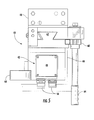
- Figs. 8-10 illustrate the system 40 shown in Figs. 4-7 being used to modify the rotor 18 of the exemplary compressor 10 shown in Fig. 1 .
- the casing 16 has been unbolted, and stationary jacks 90 have been installed between the sections of the casing 16 to create an opening in the casing 16 of approximately 18-24 inches. This opening is large enough to allow insertion of the system 40 through the opening without requiring complete removal of the casing 16 or adjacent structures.
- the rotating blades 14 in the first stage have been removed, and the system 40 has been located above or proximate to the slot 24 being modified.
- the clamp 80 is aligned with the slot 24 being modified, and the system 40 is slid axially rearward, causing the clamp 80 to slide rearward inside the slot 24 until the alignment tabs 66 abut the front surface of the rotor 18.
- the drill 42 is axially aligned with the slot 24 to machine the cavity 28 in the desired position, and the outer surface 82 of the clamp 80 engages with the interior surface of the slot 24 to hold the system 40 in place.
- the set screw 86 if present, may be rotated to further tighten the clamp 80 inside the slot 24. For example, as previously discussed with respect to Fig. 7 , rotation of the set screw 86 may force the projections 84 against the inclined surface 88 inside the clamp 80 to extend the projections 84 beyond the outer perimeter 82 of the clamp 80 to further bind the clamp 80 to the slot 24.
- the handle 64 has been rotated to move the drill 42 radially inward along the vertical axis 46 until the drill bit 54 contacts the inner surface of the slot 24 at the desired location of the cavity 28.
- a precision block 92 having the same thickness as the insert 30 may be placed on top of the mechanical stop 74, and the stud 76 may be rotated until the precision block 92 abuts the drill 42.
- the precision block 92 may then be removed from the mechanical stop 74, and the lock 78 may be applied to the stud 76 so that the resulting distance between the drill 42 and the top of the stud 76 equals the desired depth of the cavity 28 to be machined into the slot 24.
- the micrometer 68 With the drill bit 54 in contact with the inner surface of the slot 24, the micrometer 68 may be zeroed to allow accurate measurement of the radial movement of the drill 42 along the vertical axis 46.
- Fig. 10 the drill 42 has been actuated, and the handle 64 has been rotated to advance the drill 42 radially inward along the vertical axis 46.
- the drill bit 54 machines the cavity 28 into the bottom of the slot 24.
- the micrometer 68 provides a continuous indication of the depth of the drill bit 54 in the slot 24, and the mechanical stop 74 ensures that the desired depth of the cavity 28 is not exceeded.
- the handle 64 may be rotated in the opposite direction to withdraw the drill 42 radially outward along the vertical axis 46.
- the set screw 86 if present, may then be rotated to loosen the clamp 80 inside the slot 24.
- the system 40 may then be slid axially forward until the clamp 80 clears the slot 24, and the system 40 may be located proximate to or above the next slot 24 to be machined.
- the system 40 described and illustrated with respect to Figs. 4-10 provides one or more benefits over the existing technology used to modify rotors.
- the system 40 contemplated within the scope of the present invention is considerably smaller and lighter than the existing technology.
- the drill 42 and clamp 80 are designed to be located or aligned with the same slot 24, allowing the system 40 to fit within the width created by the removal of a single rotating blade 14.
- the lighter weight of the system 40 allows the system 40 to be more easily manipulated within the tight confines around the rotor 18.
- the system 40 does not require the complete removal of the casing 16 and/or adjacent structures, installation of scaffolding, or the use of an external crane to move the system 40 between slots 24, all of which result in substantial savings in preparing the rotor 18 for modification and restoring the rotor 18 to service upon completion of the modification.
Landscapes
- Engineering & Computer Science (AREA)
- Mechanical Engineering (AREA)
- General Engineering & Computer Science (AREA)
- Structures Of Non-Positive Displacement Pumps (AREA)
Applications Claiming Priority (1)
| Application Number | Priority Date | Filing Date | Title |
|---|---|---|---|
| US13/089,987 US20120269592A1 (en) | 2011-04-19 | 2011-04-19 | System and method for modifying a rotor |
Publications (1)
| Publication Number | Publication Date |
|---|---|
| EP2514924A2 true EP2514924A2 (fr) | 2012-10-24 |
Family
ID=45999675
Family Applications (1)
| Application Number | Title | Priority Date | Filing Date |
|---|---|---|---|
| EP12164333A Withdrawn EP2514924A2 (fr) | 2011-04-19 | 2012-04-16 | Système et procédé de modification d'une encoche de rotor |
Country Status (3)
| Country | Link |
|---|---|
| US (1) | US20120269592A1 (fr) |
| EP (1) | EP2514924A2 (fr) |
| CN (1) | CN102744441A (fr) |
Cited By (1)
| Publication number | Priority date | Publication date | Assignee | Title |
|---|---|---|---|---|
| EP2764936A3 (fr) * | 2013-02-08 | 2016-06-22 | General Electric Company | Système de fraisage d'aubes de rotor de turbomachine et procédé de réparation sur site de telles aubes |
Families Citing this family (8)
| Publication number | Priority date | Publication date | Assignee | Title |
|---|---|---|---|---|
| US9943920B2 (en) | 2015-03-27 | 2018-04-17 | General Electric Company | Method for electro-chemical machining turbine wheel in-situ |
| US9623492B2 (en) * | 2015-03-27 | 2017-04-18 | General Electric Company | Milling tool for portion of slot in rotor |
| US9827628B2 (en) | 2015-03-27 | 2017-11-28 | General Electric Company | Fixture for electro-chemical machining electrode |
| US20170056980A1 (en) * | 2015-08-24 | 2017-03-02 | General Electric Company | Fixture for securing component to be drilled and method of drilling same |
| US10634349B2 (en) | 2015-08-24 | 2020-04-28 | General Electric Company | Wear pad system for turbine combustion systems and method for coupling wear pad into turbine combustion system |
| US10005139B2 (en) * | 2015-12-21 | 2018-06-26 | General Electric Company | Portable milling tool with method for turbomachine milling |
| CN107060895B (zh) * | 2017-06-05 | 2019-01-01 | 上海理工大学 | 预扭动叶装配工具及装置 |
| DE102017220833A1 (de) * | 2017-11-22 | 2019-05-23 | Siemens Aktiengesellschaft | Messsystem zur Erfassung der räumlichen Lage eines Sicherungsstiftes und Verfahren zum Ausbohren eines Sicherungsstiftes |
Citations (1)
| Publication number | Priority date | Publication date | Assignee | Title |
|---|---|---|---|---|
| US20090077795A1 (en) | 2007-09-20 | 2009-03-26 | General Electric Company | Replaceable Staking Insert |
Family Cites Families (14)
| Publication number | Priority date | Publication date | Assignee | Title |
|---|---|---|---|---|
| US2868043A (en) * | 1957-05-20 | 1959-01-13 | Ollice C Robbins | Portable horizontal drill |
| US2911860A (en) * | 1958-01-28 | 1959-11-10 | Winslow Product Engineering Co | Collet foot for power tool |
| US2909949A (en) * | 1958-05-02 | 1959-10-27 | James C Winslow | Power drill with work holding device and spacing means |
| US2963927A (en) * | 1959-10-26 | 1960-12-13 | Boeing Co | Self aligning drill motor clamp |
| US3048416A (en) * | 1961-04-24 | 1962-08-07 | Harry F Rogers | Expandable pipe mandrel |
| US3115798A (en) * | 1962-08-27 | 1963-12-31 | Carlton S Donaway | Lathe spindle and collet stops |
| US3224104A (en) * | 1964-02-17 | 1965-12-21 | Ii Robert E Platt | Dial indicator gauging attachment |
| US3663115A (en) * | 1970-04-20 | 1972-05-16 | Zephyr Mfg Co | Portable drill with power drawbar clamping device |
| USRE30519E (en) * | 1979-11-15 | 1981-02-17 | Accessory support plates for a magnet base drill | |
| US5101557A (en) * | 1990-11-14 | 1992-04-07 | General Electric Company | Method for machining rotors |
| US5252010A (en) * | 1991-03-22 | 1993-10-12 | Technical Manufacturing Corporation | Adjustable stop assembly for a press |
| US5161291A (en) * | 1992-01-21 | 1992-11-10 | Westinghouse Electric Corp. | Adjustable machining apparatus for machining a cylindrical workpiece |
| JPH07290309A (ja) * | 1994-04-22 | 1995-11-07 | Hitachi Koki Co Ltd | Cチャンネル用ボール盤の芯出し機構 |
| CN1765589A (zh) * | 2003-06-27 | 2006-05-03 | 密尔沃基电动工具公司 | 电动工具、转接头及其操作方法 |
-
2011
- 2011-04-19 US US13/089,987 patent/US20120269592A1/en not_active Abandoned
-
2012
- 2012-04-16 EP EP12164333A patent/EP2514924A2/fr not_active Withdrawn
- 2012-04-19 CN CN201210129831XA patent/CN102744441A/zh active Pending
Patent Citations (1)
| Publication number | Priority date | Publication date | Assignee | Title |
|---|---|---|---|---|
| US20090077795A1 (en) | 2007-09-20 | 2009-03-26 | General Electric Company | Replaceable Staking Insert |
Cited By (2)
| Publication number | Priority date | Publication date | Assignee | Title |
|---|---|---|---|---|
| EP2764936A3 (fr) * | 2013-02-08 | 2016-06-22 | General Electric Company | Système de fraisage d'aubes de rotor de turbomachine et procédé de réparation sur site de telles aubes |
| US9988906B2 (en) | 2013-02-08 | 2018-06-05 | General Electric Company | Turbomachine rotor blade milling machine system and method of field repairing a turbomachine rotor blade |
Also Published As
| Publication number | Publication date |
|---|---|
| US20120269592A1 (en) | 2012-10-25 |
| CN102744441A (zh) | 2012-10-24 |
Similar Documents
| Publication | Publication Date | Title |
|---|---|---|
| US8402625B2 (en) | System and method for modifying a rotor | |
| EP2514924A2 (fr) | Système et procédé de modification d'une encoche de rotor | |
| US9623492B2 (en) | Milling tool for portion of slot in rotor | |
| EP2551474B1 (fr) | Procédé pour supporter un arbre dans une turbine | |
| CN102554302B (zh) | 用于机械加工护罩块的方法和装置 | |
| EP2764936A2 (fr) | Système de fraisage d'aubes de rotor de turbomachine et procédé de réparation sur site de telles aubes | |
| CN114263503B (zh) | 涡轮转子的平衡配重进入端口 | |
| EP2687729B1 (fr) | Structure de rotor | |
| DE102014118021A1 (de) | Turbomaschinen-Kaltspaltjustage | |
| EP2652270A1 (fr) | Procédé de détermination du diamètre d'un rotor équipé d'aubes mobiles d'une turbomachine | |
| JP7053142B2 (ja) | 携帯型ミル工具および、ミル処理する方法 | |
| EP2008759B1 (fr) | Accessoire et procédé d'alignement d'outils | |
| JP2016056805A (ja) | 缶型燃焼器を取り付け又は取り外し、交換し及びメンテナンスするための装置及び方法 | |
| EP3542032B1 (fr) | Outils et procédés de retrait d'aube directrice d'entrée | |
| JP6824651B2 (ja) | ターボ機械のダブテールスロットを補修するための方法及びシステム | |
| EP2730753B1 (fr) | Système pour l'assemblage et le désassemblage d'une section de turbine d'une turbine à gaz | |
| CN112743137B (zh) | 用于机加工燃气涡轮发动机的壳体的内表面中的狭槽的系统和方法 | |
| JP7019426B2 (ja) | 燃焼缶メンテナンス装置および方法 | |
| CN117703532A (zh) | 一种透平叶片安装方法及透平叶片组件 |
Legal Events
| Date | Code | Title | Description |
|---|---|---|---|
| PUAI | Public reference made under article 153(3) epc to a published international application that has entered the european phase |
Free format text: ORIGINAL CODE: 0009012 |
|
| AK | Designated contracting states |
Kind code of ref document: A2 Designated state(s): AL AT BE BG CH CY CZ DE DK EE ES FI FR GB GR HR HU IE IS IT LI LT LU LV MC MK MT NL NO PL PT RO RS SE SI SK SM TR |
|
| AX | Request for extension of the european patent |
Extension state: BA ME |
|
| STAA | Information on the status of an ep patent application or granted ep patent |
Free format text: STATUS: THE APPLICATION IS DEEMED TO BE WITHDRAWN |
|
| 18D | Application deemed to be withdrawn |
Effective date: 20151103 |