EP2514927A2 - Unabhängig gesteuerte Gasturbineneintrittsleitschaufeln und variable Leitschaufeln - Google Patents
Unabhängig gesteuerte Gasturbineneintrittsleitschaufeln und variable Leitschaufeln Download PDFInfo
- Publication number
- EP2514927A2 EP2514927A2 EP12164847A EP12164847A EP2514927A2 EP 2514927 A2 EP2514927 A2 EP 2514927A2 EP 12164847 A EP12164847 A EP 12164847A EP 12164847 A EP12164847 A EP 12164847A EP 2514927 A2 EP2514927 A2 EP 2514927A2
- Authority
- EP
- European Patent Office
- Prior art keywords
- vsv
- igv
- servo
- vsvs
- cylinder set
- Prior art date
- Legal status (The legal status is an assumption and is not a legal conclusion. Google has not performed a legal analysis and makes no representation as to the accuracy of the status listed.)
- Granted
Links
Images



Classifications
-
- F—MECHANICAL ENGINEERING; LIGHTING; HEATING; WEAPONS; BLASTING
- F01—MACHINES OR ENGINES IN GENERAL; ENGINE PLANTS IN GENERAL; STEAM ENGINES
- F01D—NON-POSITIVE DISPLACEMENT MACHINES OR ENGINES, e.g. STEAM TURBINES
- F01D17/00—Regulating or controlling by varying flow
- F01D17/10—Final actuators
- F01D17/12—Final actuators arranged in stator parts
- F01D17/14—Final actuators arranged in stator parts varying effective cross-sectional area of nozzles or guide conduits
- F01D17/16—Final actuators arranged in stator parts varying effective cross-sectional area of nozzles or guide conduits by means of nozzle vanes
- F01D17/162—Final actuators arranged in stator parts varying effective cross-sectional area of nozzles or guide conduits by means of nozzle vanes for axial flow, i.e. the vanes turning around axes which are essentially perpendicular to the rotor centre line
-
- F—MECHANICAL ENGINEERING; LIGHTING; HEATING; WEAPONS; BLASTING
- F02—COMBUSTION ENGINES; HOT-GAS OR COMBUSTION-PRODUCT ENGINE PLANTS
- F02C—GAS-TURBINE PLANTS; AIR INTAKES FOR JET-PROPULSION PLANTS; CONTROLLING FUEL SUPPLY IN AIR-BREATHING JET-PROPULSION PLANTS
- F02C7/00—Features, components parts, details or accessories, not provided for in, or of interest apart form groups F02C1/00 - F02C6/00; Air intakes for jet-propulsion plants
- F02C7/04—Air intakes for gas-turbine plants or jet-propulsion plants
- F02C7/057—Control or regulation
-
- F—MECHANICAL ENGINEERING; LIGHTING; HEATING; WEAPONS; BLASTING
- F05—INDEXING SCHEMES RELATING TO ENGINES OR PUMPS IN VARIOUS SUBCLASSES OF CLASSES F01-F04
- F05D—INDEXING SCHEME FOR ASPECTS RELATING TO NON-POSITIVE-DISPLACEMENT MACHINES OR ENGINES, GAS-TURBINES OR JET-PROPULSION PLANTS
- F05D2240/00—Components
- F05D2240/10—Stators
- F05D2240/12—Fluid guiding means, e.g. vanes
-
- F—MECHANICAL ENGINEERING; LIGHTING; HEATING; WEAPONS; BLASTING
- F05—INDEXING SCHEMES RELATING TO ENGINES OR PUMPS IN VARIOUS SUBCLASSES OF CLASSES F01-F04
- F05D—INDEXING SCHEME FOR ASPECTS RELATING TO NON-POSITIVE-DISPLACEMENT MACHINES OR ENGINES, GAS-TURBINES OR JET-PROPULSION PLANTS
- F05D2260/00—Function
- F05D2260/40—Transmission of power
- F05D2260/406—Transmission of power through hydraulic systems
Definitions
- the invention relates generally to gas turbines and, more specifically, to variable stator vane assemblies used with gas turbines.
- air is pressurized in a compressor and channeled to a combustor where it is mixed with fuel and ignited for generating hot combustion gases.
- the hot combustion gases flow downstream into one or more turbine stages, which extract energy therefrom for producing useful work.
- At least some known compressors have a plurality of axial stages that compress the air in turn as it flows downstream.
- Each compressor stage may include a row of rotor blades extending radially outwardly from a compressor spool or disk, and a cooperating row of stator vanes extending radially inwardly from an annular casing.
- VSVs variable stator vanes
- the invention resides in a system that adjusts positions of gas turbine inlet guide vanes (IGVs) and variable stator vanes (VSVs).
- the system includes a hydraulic power unit providing a supply of hydraulic fluid, an IGV servo in fluid communication with the hydraulic power unit, and a VSV servo in fluid communication with the hydraulic power unit.
- An IGV cylinder set is provided in fluid communication with the hydraulic power unit via the IGV servo and is connected to the IGVs.
- the IGV cylinder set effects displacement of the IGVs between a closed position and a fully open position.
- a VSV cylinder set is provided in fluid communication with the hydraulic power unit via the VSV servo.
- the VSVs include multiple stages linked together with a torque shaft.
- the VSV cylinder set is connected to the torque shaft, and the VSV cylinder set effects simultaneous displacement of the stages of the VSVs between a closed position and a fully open position.
- the IGV servo and the VSV servo respectively control delivery of hydraulic fluid from the hydraulic power unit to the IGV cylinder set and the VSV cylinder set, and the IGV servo and the VSV servo are independently controllable.
- the invention resides in a gas turbine including a compressor receiving inlet air and mixing the inlet air with fuel, a combustor that receives the inlet air and fuel mixture and that combusts the mixture to produce hot products of combustion, and a turbine receiving the hot products of combustion and converting the hot products of combustion into work.
- the compressor includes inlet guide vanes (IGVs) and variable stator vanes (VSVs), where respective positions of the IGVs and the VSVs affect a performance efficiency of the gas turbine.
- the compressor includes the system described above for adjusting the positions of the IGVs and the VSVs.
- the invention resides in a method of adjusting positions of gas turbine inlet guide vanes (IGVs) and variable stator vanes (VSVs) including the steps of providing a supply of hydraulic fluid with a hydraulic power unit; connecting an IGV servo in fluid communication with the hydraulic power unit; connecting a VSV servo in fluid communication with the hydraulic power unit; displacing the IGVs between a closed position and a fully open position with an IGV cylinder set in fluid communication with the hydraulic power unit via the IGV servo; and displacing the VSVs between a closed position and a fully open position with a VSV cylinder set in fluid communication with the hydraulic power unit via the VSV servo, the VSVs including multiple stages linked together with a torque shaft, wherein VSV cylinder set is connected to the torque shaft, the step of displacing the VSVs comprising simultaneously displacing the stages of the VSVs via the torque shaft.
- the IGV servo and the VSV servo respectively control delivery of hydraulic
- FIG. 1 is a schematic block diagram of a gas turbine 10 including a hydraulic actuation system 12 for independently controlling gas turbine compressor inlet guide vanes (IGVs) 14 and variable stator vanes (VSVs) 16.
- IGVs gas turbine compressor inlet guide vanes
- VSVs variable stator vanes
- air is pressurized in a compressor 18 and mixed with fuel and ignited in a combustor 20 producing hot combustion gases.
- the hot combustion gases flow downstream into a turbine 22 including one or more turbine stages that extract energy from the hot combustion gases to produce useful work.
- the actuation system 12 provides for independently-controllable IGVs 14 and VSVs 16 via hydraulic actuators connected to a hydraulic power unit 24 and controlled by a hydraulic control assembly 26.
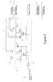
- FIGS. 2 and 3 show a hydraulic circuit diagram of the actuation system 12.
- hydraulic fluid at a nominal pressure is provided from a reservoir in the hydraulic power unit 24.
- Hydraulic fluid is provided to IGV actuators or cylinders 28 and VSV actuators or cylinders 30 under the control of the hydraulic control assembly 26.
- two cylinders 28, 30 are associated with each of the IGVs and the VSVs, one each corresponding to each side of the unit.
- the cylinders 28, 30 are controlled to control respective positions of the IGVs 14 and the VSVs 16 between a closed position restricting air flow and a fully opened position permitting maximum air flow.
- the hydraulic fluid supply from the hydraulic power unit 24 is piped to a manifold 32 that splits the supply stream between the IGV and the VSV portions of the actuation system 12.
- a filter 34 serves to filter the fluid upon entry in the manifold 32 to protect downstream valves from potential debris and the like.
- Fluid flow to the cylinders 28, 30 is controlled by an IGV servo valve 36 for the IGVs and a VSV servo valve 38 for the VSVs.
- the IGV servo 36 and the VSV servo 38 respectively control delivery of hydraulic fluid from the hydraulic power unit 24 to the IGV cylinders 28 and the VSV cylinders 30 and are independently controllable.
- the servo valves 36, 38 act to port the fluid supply to either the head or cap end of the cylinders 28, 30 to produce either a "retract" or "extend” motion of the actuator rods 40, 42.
- retracting the rods 40, 42 corresponds to opening the vanes 14, 16, and extending the rods 40, 42 corresponds to closing the vanes 14, 16.
- Hydraulic fluid is ported away from the non-supply side of the actuators 28, 30, either head or cap side depending on intended motion, back to the control module 26.
- the control module 26 communicates with the main gas turbine control system and ports fluid accordingly to reach and/or maintain desired vane positions for the IGVs and the VSVs.
- exhaust temperature can be measured as an indication of turbine operation/efficiency. Positions of the IGVs 14 and the VSVs 16 may be adjusted according to the exhaust temperature to improve gas turbine output.
- the circuit includes inline screens 44 between the servos 36, 38 and the cylinders 28, 30.
- the inline screens 44 serve to prevent debris from getting into the servo valves 36, 38, particularly as hydraulic fluid is returned to the servos 36, 38 from the cylinders 28, 30.
- An air bleed 46 enables air to be removed from the system at high points.
- the air bleed 46 comprises a manual valve or button that requires operator actuation during maintenance or shut down operations.
- FIG. 4 shows an exemplary IGV actuator showing the internal LVDTs 48.
- each actuator is provided with two independent LVDTs 48.
- a rod end plug 50 seals the LVDTs 48 and prevents field adjustment.
- each of the IGV side and the VSV side of the hydraulic circuit includes trip valves 52 that are used to port the hydraulic fluid to one side of each cylinder 28, 30, forcing it into a position in which the IGVs 14 and the VSVs 16 are closed.
- the trip valves 52 force the cylinders 28, 30 into their extended position.
- Trip commands are used during gas turbine emergency shut down, which could be caused by various factors internal or external to the IGV/VSV system.
- This trip functionality provides compressor protection during emergency shut down situations to limit airflow and prevent the unit from dangerous over-speed events. Additionally, in a preferred construction, the trip valves are configured such that the IGVs always lead the VSVs to close, thereby preventing a compressor stall or surge event.
- FIGS. 5 and 6 are perspective views of right and left side sections of the compressor showing the IGVs 14 and the VSVs 16. As shown, there are two actuators/cylinders 28, 30 for each of the IGVs 14 and the VSVs 16, one on each side.
- the IGVs 14 are connected to a unison ring 54 attached to a vane pin (inside the c-channel part of the unison ring).
- the unison ring 54 moves the vanes 14 in tandem, and the IGV cylinders 28 act on the unison ring 54.
- the IGVs 14 comprise a single stage of variable vanes closest to the air inlet of the gas turbine compressor.
- the VSVs 16 comprise multi-stage variable vanes in this instance with three individual stages linked together with a mechanical shaft or torque shaft 56.
- Rods 58 are connected to the torque shaft 56 at one end and are connected at an opposite end to unison rings 54 of each of the VSV stages.
- the VSV cylinders 30 act on the torque shaft 56.
- the described embodiments enable hydraulic actuation of separate sets of variable vanes independently for improved gas turbine efficiency, performance and load turn down capability. Independently controllable vane angle settings between two separate sets of vanes allow the gas turbine compressor to operate more effectively. Also, the trip functionality provides compressor protection during emergency shut down situations. Packaging a pair of servo and trip valves together with a hydraulic manifold with a single supply and a single drain connection allows for a smaller installed footprint.
- the described embodiments provide a simple interface to the field installed hydraulic interconnect piping to and from the reservoir. Since the actuators are mounted to the gas turbine casings, the IGV/VSV system hardware can be shipped installed on the gas turbine, thereby reducing installation time and more easily maintaining cleanliness of the hydraulic components.
Landscapes
- Engineering & Computer Science (AREA)
- Chemical & Material Sciences (AREA)
- Combustion & Propulsion (AREA)
- Mechanical Engineering (AREA)
- General Engineering & Computer Science (AREA)
- Control Of Turbines (AREA)
- Structures Of Non-Positive Displacement Pumps (AREA)
- Supercharger (AREA)
Applications Claiming Priority (1)
| Application Number | Priority Date | Filing Date | Title |
|---|---|---|---|
| US13/091,540 US9068470B2 (en) | 2011-04-21 | 2011-04-21 | Independently-controlled gas turbine inlet guide vanes and variable stator vanes |
Publications (3)
| Publication Number | Publication Date |
|---|---|
| EP2514927A2 true EP2514927A2 (de) | 2012-10-24 |
| EP2514927A3 EP2514927A3 (de) | 2018-01-10 |
| EP2514927B1 EP2514927B1 (de) | 2019-10-23 |
Family
ID=46084804
Family Applications (1)
| Application Number | Title | Priority Date | Filing Date |
|---|---|---|---|
| EP12164847.1A Active EP2514927B1 (de) | 2011-04-21 | 2012-04-19 | Unabhängig gesteuerte Gasturbineneintrittsleitschaufeln und variable Leitschaufeln |
Country Status (3)
| Country | Link |
|---|---|
| US (1) | US9068470B2 (de) |
| EP (1) | EP2514927B1 (de) |
| CN (1) | CN102758654B (de) |
Cited By (9)
| Publication number | Priority date | Publication date | Assignee | Title |
|---|---|---|---|---|
| CN102966386A (zh) * | 2012-11-12 | 2013-03-13 | 国家电网公司 | 一种电液伺服控制装置 |
| US9492780B2 (en) | 2014-01-16 | 2016-11-15 | Bha Altair, Llc | Gas turbine inlet gas phase contaminant removal |
| EP2508762A3 (de) * | 2011-04-08 | 2018-04-11 | General Electric Company | Regelung eines Verdichtungssystems mit unabhängig voneinander betätigten Eintrittsleitschaufeln und / oder Leitschaufeln |
| US10502136B2 (en) | 2014-10-06 | 2019-12-10 | Bha Altair, Llc | Filtration system for use in a gas turbine engine assembly and method of assembling thereof |
| EP3594456A1 (de) * | 2018-07-11 | 2020-01-15 | MTU Aero Engines GmbH | Verstelleinrichtung und verfahren zur verstellung eines leitgitters einer turbomaschine |
| EP3650711A1 (de) * | 2018-11-06 | 2020-05-13 | Rolls-Royce plc | Modularer linearantrieb |
| EP3453892B1 (de) * | 2017-08-22 | 2020-06-24 | Hamilton Sundstrand Corporation | Elektrisch-hydraulisches betätigungssystem für eine sicherheitskritische anwendung |
| CN114922694A (zh) * | 2022-06-10 | 2022-08-19 | 中国联合重型燃气轮机技术有限公司 | 用于驱动可调导叶的燃气轮机流体驱动系统 |
| EP4390064A1 (de) * | 2022-12-23 | 2024-06-26 | Rolls-Royce Deutschland Ltd & Co KG | Gasturbinentriebwerkssteuerungssystem und verfahren zur begrenzung der turbinenüberdrehzahl bei einem wellenversagen |
Families Citing this family (27)
| Publication number | Priority date | Publication date | Assignee | Title |
|---|---|---|---|---|
| US20120134783A1 (en) | 2010-11-30 | 2012-05-31 | General Electric Company | System and method for operating a compressor |
| US20130074512A1 (en) * | 2011-09-23 | 2013-03-28 | Steven William Tillery | Inlet fluid flow and impingement angle control |
| DE102012007129A1 (de) * | 2012-04-10 | 2013-10-10 | Rolls-Royce Deutschland Ltd & Co Kg | Leitschaufelverstellvorrichtung einer Gasturbine |
| US9500200B2 (en) * | 2012-04-19 | 2016-11-22 | General Electric Company | Systems and methods for detecting the onset of compressor stall |
| EP2971598B1 (de) * | 2013-03-13 | 2019-08-21 | United Technologies Corporation | Steuersystem mit verstellbarer leitschaufel |
| US10001066B2 (en) * | 2014-08-28 | 2018-06-19 | General Electric Company | Rotary actuator for variable geometry vanes |
| US10443509B2 (en) | 2014-10-31 | 2019-10-15 | General Electric Company | System and method for turbomachinery vane prognostics and diagnostics |
| US20170108032A1 (en) * | 2015-10-16 | 2017-04-20 | General Electric Company | Stepped shaft assembly |
| US9982686B2 (en) | 2015-11-04 | 2018-05-29 | General Electric Company | Turnbuckle dampening links |
| US10215047B2 (en) | 2015-12-28 | 2019-02-26 | General Electric Company | Actuation system utilizing MEMS technology |
| US10408217B2 (en) | 2016-03-15 | 2019-09-10 | General Electric Company | Controlling a compressor of a gas turbine engine |
| US10400680B2 (en) | 2016-09-28 | 2019-09-03 | General Electric Company | System and method for synchronizing the operation of airfoil actuators of a gas turbine engine |
| US10519964B2 (en) | 2016-12-06 | 2019-12-31 | General Electric Company | System and method for turbomachinery rotor and blade prognostics and diagnostics |
| US10125779B2 (en) | 2016-12-06 | 2018-11-13 | General Electric Company | System and method for turbomachinery vane diagnostics |
| US10961919B2 (en) | 2017-08-29 | 2021-03-30 | Pratt & Whitney Canada Corp | Corrected parameters control logic for variable geometry mechanisms |
| US10704411B2 (en) | 2018-08-03 | 2020-07-07 | General Electric Company | Variable vane actuation system for a turbo machine |
| CN109764012B (zh) * | 2019-03-06 | 2024-05-07 | 上海电气燃气轮机有限公司 | 一种液压执行机构及燃气轮机 |
| GB201903062D0 (en) * | 2019-03-07 | 2019-04-24 | Rolls Royce Plc | Fuel control system |
| US20220098995A1 (en) * | 2020-07-23 | 2022-03-31 | Williams International Co., L.L.C. | Gas-turbine-engine overspeed protection system |
| US20230265862A1 (en) | 2022-02-21 | 2023-08-24 | General Electric Company | Turbofan engine having angled inlet pre-swirl vanes |
| US11725526B1 (en) | 2022-03-08 | 2023-08-15 | General Electric Company | Turbofan engine having nacelle with non-annular inlet |
| CN114576012B (zh) * | 2022-03-29 | 2023-09-26 | 华北电力科学研究院有限责任公司 | 燃气轮机进口导叶调节方法及装置 |
| CN116412178A (zh) * | 2023-04-04 | 2023-07-11 | 上海置道液压控制技术有限公司 | 一种燃机进气导叶的油动机执行系统 |
| US12209557B1 (en) | 2023-11-30 | 2025-01-28 | General Electric Company | Gas turbine engine with forward swept outlet guide vanes |
| US12385430B2 (en) | 2023-11-30 | 2025-08-12 | General Electric Company | Gas turbine engine with forward swept outlet guide vanes |
| US12228037B1 (en) | 2023-12-04 | 2025-02-18 | General Electric Company | Guide vane assembly with fixed and variable pitch inlet guide vanes |
| US12313021B1 (en) | 2024-03-14 | 2025-05-27 | General Electric Company | Outer nacelle with inlet guide vanes and acoustic treatment |
Family Cites Families (26)
| Publication number | Priority date | Publication date | Assignee | Title |
|---|---|---|---|---|
| US2780064A (en) * | 1953-11-10 | 1957-02-05 | Gen Dynamics Corp | Accumulator for hydraulic systems |
| US2931168A (en) * | 1955-05-24 | 1960-04-05 | Gen Electric | Variable stator engine control system |
| US3973391A (en) | 1974-08-08 | 1976-08-10 | Westinghouse Electric Corporation | Control apparatus for modulating the inlet guide vanes of a gas turbine employed in a combined cycle electric power generating plant as a function of load or inlet blade path temperature |
| US3914066A (en) * | 1974-09-27 | 1975-10-21 | Gen Motors Corp | Vane actuation system |
| GB2206381B (en) | 1987-06-30 | 1991-10-09 | Rolls Royce Plc | A variable stator vane arrangement for a compressor |
| US5102049A (en) | 1987-11-24 | 1992-04-07 | The United States Of America As Represented By The Secretary Of The Air Force | Vane control mechanism |
| GB2227527B (en) * | 1989-01-25 | 1993-06-09 | Rolls Royce Plc | A variable stator vane arrangement for an axial flow compressor |
| US5622473A (en) | 1995-11-17 | 1997-04-22 | General Electric Company | Variable stator vane assembly |
| JP3600438B2 (ja) * | 1998-05-22 | 2004-12-15 | 三菱重工業株式会社 | ガスタービンの可変翼回転装置 |
| US6209198B1 (en) | 1998-12-16 | 2001-04-03 | General Electric Company | Method of assembling a variable stator vane assembly |
| US6226974B1 (en) | 1999-06-25 | 2001-05-08 | General Electric Co. | Method of operation of industrial gas turbine for optimal performance |
| US6794766B2 (en) | 2001-06-29 | 2004-09-21 | General Electric Company | Method and operational strategy for controlling variable stator vanes of a gas turbine power generator compressor component during under-frequency events |
| US6735955B2 (en) | 2001-10-10 | 2004-05-18 | Goodrich Pump & Engine Control Systems, Inc. | Control system for positioning compressor inlet guide vanes |
| US7220098B2 (en) | 2003-05-27 | 2007-05-22 | General Electric Company | Wear resistant variable stator vane assemblies |
| GB2402180B (en) | 2003-05-30 | 2006-09-20 | Rolls Royce Plc | Variable stator vane actuating levers |
| GB0326544D0 (en) | 2003-11-14 | 2003-12-17 | Rolls Royce Plc | Variable stator vane arrangement for a compressor |
| US7096657B2 (en) | 2003-12-30 | 2006-08-29 | Honeywell International, Inc. | Gas turbine engine electromechanical variable inlet guide vane actuation system |
| GB2412947B (en) | 2004-04-07 | 2006-06-14 | Rolls Royce Plc | Variable stator vane assemblies |
| US7125222B2 (en) | 2004-04-14 | 2006-10-24 | General Electric Company | Gas turbine engine variable vane assembly |
| FR2885969B1 (fr) | 2005-05-17 | 2007-08-10 | Snecma Moteurs Sa | Systeme de commande d'etages d'aubes de stator a angle de calage variable de turbomachine |
| US7278819B2 (en) | 2005-07-05 | 2007-10-09 | General Electric Company | Variable stator vane lever arm assembly and method of assembling same |
| JP4699130B2 (ja) * | 2005-08-03 | 2011-06-08 | 三菱重工業株式会社 | ガスタービンの入口案内翼制御装置 |
| US7445427B2 (en) | 2005-12-05 | 2008-11-04 | General Electric Company | Variable stator vane assembly and bushing thereof |
| US7413401B2 (en) | 2006-01-17 | 2008-08-19 | General Electric Company | Methods and apparatus for controlling variable stator vanes |
| JP2010196550A (ja) * | 2009-02-24 | 2010-09-09 | Mitsubishi Heavy Ind Ltd | 回転軸とレバーの取付構造、回転軸とレバーの取付方法、及び、流体機械 |
| US8152406B1 (en) * | 2010-11-08 | 2012-04-10 | Saudi Arabian Oil Company | Crash barrier with over-pressure relief system |
-
2011
- 2011-04-21 US US13/091,540 patent/US9068470B2/en not_active Expired - Fee Related
-
2012
- 2012-04-19 EP EP12164847.1A patent/EP2514927B1/de active Active
- 2012-04-23 CN CN201210138743.6A patent/CN102758654B/zh not_active Expired - Fee Related
Non-Patent Citations (1)
| Title |
|---|
| None |
Cited By (11)
| Publication number | Priority date | Publication date | Assignee | Title |
|---|---|---|---|---|
| EP2508762A3 (de) * | 2011-04-08 | 2018-04-11 | General Electric Company | Regelung eines Verdichtungssystems mit unabhängig voneinander betätigten Eintrittsleitschaufeln und / oder Leitschaufeln |
| CN102966386A (zh) * | 2012-11-12 | 2013-03-13 | 国家电网公司 | 一种电液伺服控制装置 |
| CN102966386B (zh) * | 2012-11-12 | 2016-06-08 | 国家电网公司 | 一种电液伺服控制装置 |
| US9492780B2 (en) | 2014-01-16 | 2016-11-15 | Bha Altair, Llc | Gas turbine inlet gas phase contaminant removal |
| US10502136B2 (en) | 2014-10-06 | 2019-12-10 | Bha Altair, Llc | Filtration system for use in a gas turbine engine assembly and method of assembling thereof |
| EP3453892B1 (de) * | 2017-08-22 | 2020-06-24 | Hamilton Sundstrand Corporation | Elektrisch-hydraulisches betätigungssystem für eine sicherheitskritische anwendung |
| EP3594456A1 (de) * | 2018-07-11 | 2020-01-15 | MTU Aero Engines GmbH | Verstelleinrichtung und verfahren zur verstellung eines leitgitters einer turbomaschine |
| EP3650711A1 (de) * | 2018-11-06 | 2020-05-13 | Rolls-Royce plc | Modularer linearantrieb |
| CN114922694A (zh) * | 2022-06-10 | 2022-08-19 | 中国联合重型燃气轮机技术有限公司 | 用于驱动可调导叶的燃气轮机流体驱动系统 |
| EP4390064A1 (de) * | 2022-12-23 | 2024-06-26 | Rolls-Royce Deutschland Ltd & Co KG | Gasturbinentriebwerkssteuerungssystem und verfahren zur begrenzung der turbinenüberdrehzahl bei einem wellenversagen |
| US12140090B2 (en) | 2022-12-23 | 2024-11-12 | Rolls-Royce Deutschland Ltd & Co Kg | Gas turbine engine control system and method for limiting turbine overspeed in case of a shaft failure |
Also Published As
| Publication number | Publication date |
|---|---|
| EP2514927A3 (de) | 2018-01-10 |
| CN102758654A (zh) | 2012-10-31 |
| US20120269613A1 (en) | 2012-10-25 |
| US9068470B2 (en) | 2015-06-30 |
| CN102758654B (zh) | 2015-09-23 |
| EP2514927B1 (de) | 2019-10-23 |
Similar Documents
| Publication | Publication Date | Title |
|---|---|---|
| EP2514927B1 (de) | Unabhängig gesteuerte Gasturbineneintrittsleitschaufeln und variable Leitschaufeln | |
| US11448127B2 (en) | Translating inlet for adjusting airflow distortion in gas turbine engine | |
| US9103228B2 (en) | Variable stator vane control system | |
| JP6050870B2 (ja) | 可変形状ベーンのための回転式アクチュエータ | |
| US10563589B2 (en) | Engine overspeed protection with thrust control | |
| EP3219956A2 (de) | Turbinenmotorauswerferdrosselungssteuerung | |
| CN101498244A (zh) | 用于涡轮冷却的装置及相关方法 | |
| CN102171418A (zh) | 控制包括筒形连杆的燃气涡轮发动机的变几何设备的系统 | |
| EP3163053A1 (de) | Ablassventilanordnung für gasturbine | |
| GB2536357A (en) | Gas bleed arrangement | |
| US10590856B2 (en) | Gas turbine engine having an annular core bleed | |
| US10309246B2 (en) | Passive clearance control system for gas turbomachine | |
| US10408217B2 (en) | Controlling a compressor of a gas turbine engine | |
| US11401825B2 (en) | Gas turbine engine control system and method for limiting turbine overspeed in case of a shaft failure | |
| EP2941538B1 (de) | Verfahren zum axialschubausgleich, turbine und turbinenmotor | |
| US9429036B2 (en) | Cooling system for control valve actuators | |
| GB2521508A (en) | Energy efficient pump system | |
| EP3483418B1 (de) | Zwischengekühlte gekühlte kühlungsintegrierte luftkreislaufmaschine |
Legal Events
| Date | Code | Title | Description |
|---|---|---|---|
| PUAI | Public reference made under article 153(3) epc to a published international application that has entered the european phase |
Free format text: ORIGINAL CODE: 0009012 |
|
| AK | Designated contracting states |
Kind code of ref document: A2 Designated state(s): AL AT BE BG CH CY CZ DE DK EE ES FI FR GB GR HR HU IE IS IT LI LT LU LV MC MK MT NL NO PL PT RO RS SE SI SK SM TR |
|
| AX | Request for extension of the european patent |
Extension state: BA ME |
|
| PUAL | Search report despatched |
Free format text: ORIGINAL CODE: 0009013 |
|
| AK | Designated contracting states |
Kind code of ref document: A3 Designated state(s): AL AT BE BG CH CY CZ DE DK EE ES FI FR GB GR HR HU IE IS IT LI LT LU LV MC MK MT NL NO PL PT RO RS SE SI SK SM TR |
|
| AX | Request for extension of the european patent |
Extension state: BA ME |
|
| RIC1 | Information provided on ipc code assigned before grant |
Ipc: F01D 17/16 20060101AFI20171205BHEP Ipc: F02C 7/057 20060101ALI20171205BHEP |
|
| STAA | Information on the status of an ep patent application or granted ep patent |
Free format text: STATUS: REQUEST FOR EXAMINATION WAS MADE |
|
| 17P | Request for examination filed |
Effective date: 20180710 |
|
| RBV | Designated contracting states (corrected) |
Designated state(s): AL AT BE BG CH CY CZ DE DK EE ES FI FR GB GR HR HU IE IS IT LI LT LU LV MC MK MT NL NO PL PT RO RS SE SI SK SM TR |
|
| GRAP | Despatch of communication of intention to grant a patent |
Free format text: ORIGINAL CODE: EPIDOSNIGR1 |
|
| STAA | Information on the status of an ep patent application or granted ep patent |
Free format text: STATUS: GRANT OF PATENT IS INTENDED |
|
| INTG | Intention to grant announced |
Effective date: 20190509 |
|
| GRAS | Grant fee paid |
Free format text: ORIGINAL CODE: EPIDOSNIGR3 |
|
| GRAA | (expected) grant |
Free format text: ORIGINAL CODE: 0009210 |
|
| STAA | Information on the status of an ep patent application or granted ep patent |
Free format text: STATUS: THE PATENT HAS BEEN GRANTED |
|
| AK | Designated contracting states |
Kind code of ref document: B1 Designated state(s): AL AT BE BG CH CY CZ DE DK EE ES FI FR GB GR HR HU IE IS IT LI LT LU LV MC MK MT NL NO PL PT RO RS SE SI SK SM TR |
|
| REG | Reference to a national code |
Ref country code: GB Ref legal event code: FG4D |
|
| REG | Reference to a national code |
Ref country code: CH Ref legal event code: EP |
|
| REG | Reference to a national code |
Ref country code: IE Ref legal event code: FG4D |
|
| REG | Reference to a national code |
Ref country code: DE Ref legal event code: R096 Ref document number: 602012065014 Country of ref document: DE |
|
| REG | Reference to a national code |
Ref country code: AT Ref legal event code: REF Ref document number: 1193861 Country of ref document: AT Kind code of ref document: T Effective date: 20191115 |
|
| REG | Reference to a national code |
Ref country code: NL Ref legal event code: MP Effective date: 20191023 |
|
| REG | Reference to a national code |
Ref country code: LT Ref legal event code: MG4D |
|
| PG25 | Lapsed in a contracting state [announced via postgrant information from national office to epo] |
Ref country code: FI Free format text: LAPSE BECAUSE OF FAILURE TO SUBMIT A TRANSLATION OF THE DESCRIPTION OR TO PAY THE FEE WITHIN THE PRESCRIBED TIME-LIMIT Effective date: 20191023 Ref country code: PT Free format text: LAPSE BECAUSE OF FAILURE TO SUBMIT A TRANSLATION OF THE DESCRIPTION OR TO PAY THE FEE WITHIN THE PRESCRIBED TIME-LIMIT Effective date: 20200224 Ref country code: BG Free format text: LAPSE BECAUSE OF FAILURE TO SUBMIT A TRANSLATION OF THE DESCRIPTION OR TO PAY THE FEE WITHIN THE PRESCRIBED TIME-LIMIT Effective date: 20200123 Ref country code: SE Free format text: LAPSE BECAUSE OF FAILURE TO SUBMIT A TRANSLATION OF THE DESCRIPTION OR TO PAY THE FEE WITHIN THE PRESCRIBED TIME-LIMIT Effective date: 20191023 Ref country code: LV Free format text: LAPSE BECAUSE OF FAILURE TO SUBMIT A TRANSLATION OF THE DESCRIPTION OR TO PAY THE FEE WITHIN THE PRESCRIBED TIME-LIMIT Effective date: 20191023 Ref country code: NL Free format text: LAPSE BECAUSE OF FAILURE TO SUBMIT A TRANSLATION OF THE DESCRIPTION OR TO PAY THE FEE WITHIN THE PRESCRIBED TIME-LIMIT Effective date: 20191023 Ref country code: LT Free format text: LAPSE BECAUSE OF FAILURE TO SUBMIT A TRANSLATION OF THE DESCRIPTION OR TO PAY THE FEE WITHIN THE PRESCRIBED TIME-LIMIT Effective date: 20191023 Ref country code: ES Free format text: LAPSE BECAUSE OF FAILURE TO SUBMIT A TRANSLATION OF THE DESCRIPTION OR TO PAY THE FEE WITHIN THE PRESCRIBED TIME-LIMIT Effective date: 20191023 Ref country code: NO Free format text: LAPSE BECAUSE OF FAILURE TO SUBMIT A TRANSLATION OF THE DESCRIPTION OR TO PAY THE FEE WITHIN THE PRESCRIBED TIME-LIMIT Effective date: 20200123 Ref country code: PL Free format text: LAPSE BECAUSE OF FAILURE TO SUBMIT A TRANSLATION OF THE DESCRIPTION OR TO PAY THE FEE WITHIN THE PRESCRIBED TIME-LIMIT Effective date: 20191023 Ref country code: GR Free format text: LAPSE BECAUSE OF FAILURE TO SUBMIT A TRANSLATION OF THE DESCRIPTION OR TO PAY THE FEE WITHIN THE PRESCRIBED TIME-LIMIT Effective date: 20200124 |
|
| PGFP | Annual fee paid to national office [announced via postgrant information from national office to epo] |
Ref country code: GB Payment date: 20200323 Year of fee payment: 9 |
|
| PG25 | Lapsed in a contracting state [announced via postgrant information from national office to epo] |
Ref country code: IS Free format text: LAPSE BECAUSE OF FAILURE TO SUBMIT A TRANSLATION OF THE DESCRIPTION OR TO PAY THE FEE WITHIN THE PRESCRIBED TIME-LIMIT Effective date: 20200224 Ref country code: HR Free format text: LAPSE BECAUSE OF FAILURE TO SUBMIT A TRANSLATION OF THE DESCRIPTION OR TO PAY THE FEE WITHIN THE PRESCRIBED TIME-LIMIT Effective date: 20191023 Ref country code: RS Free format text: LAPSE BECAUSE OF FAILURE TO SUBMIT A TRANSLATION OF THE DESCRIPTION OR TO PAY THE FEE WITHIN THE PRESCRIBED TIME-LIMIT Effective date: 20191023 |
|
| PG25 | Lapsed in a contracting state [announced via postgrant information from national office to epo] |
Ref country code: AL Free format text: LAPSE BECAUSE OF FAILURE TO SUBMIT A TRANSLATION OF THE DESCRIPTION OR TO PAY THE FEE WITHIN THE PRESCRIBED TIME-LIMIT Effective date: 20191023 |
|
| REG | Reference to a national code |
Ref country code: DE Ref legal event code: R097 Ref document number: 602012065014 Country of ref document: DE |
|
| PG2D | Information on lapse in contracting state deleted |
Ref country code: IS |
|
| PG25 | Lapsed in a contracting state [announced via postgrant information from national office to epo] |
Ref country code: DK Free format text: LAPSE BECAUSE OF FAILURE TO SUBMIT A TRANSLATION OF THE DESCRIPTION OR TO PAY THE FEE WITHIN THE PRESCRIBED TIME-LIMIT Effective date: 20191023 Ref country code: CZ Free format text: LAPSE BECAUSE OF FAILURE TO SUBMIT A TRANSLATION OF THE DESCRIPTION OR TO PAY THE FEE WITHIN THE PRESCRIBED TIME-LIMIT Effective date: 20191023 Ref country code: RO Free format text: LAPSE BECAUSE OF FAILURE TO SUBMIT A TRANSLATION OF THE DESCRIPTION OR TO PAY THE FEE WITHIN THE PRESCRIBED TIME-LIMIT Effective date: 20191023 Ref country code: EE Free format text: LAPSE BECAUSE OF FAILURE TO SUBMIT A TRANSLATION OF THE DESCRIPTION OR TO PAY THE FEE WITHIN THE PRESCRIBED TIME-LIMIT Effective date: 20191023 Ref country code: IS Free format text: LAPSE BECAUSE OF FAILURE TO SUBMIT A TRANSLATION OF THE DESCRIPTION OR TO PAY THE FEE WITHIN THE PRESCRIBED TIME-LIMIT Effective date: 20200223 |
|
| PGFP | Annual fee paid to national office [announced via postgrant information from national office to epo] |
Ref country code: DE Payment date: 20200319 Year of fee payment: 9 |
|
| REG | Reference to a national code |
Ref country code: AT Ref legal event code: MK05 Ref document number: 1193861 Country of ref document: AT Kind code of ref document: T Effective date: 20191023 |
|
| PLBE | No opposition filed within time limit |
Free format text: ORIGINAL CODE: 0009261 |
|
| STAA | Information on the status of an ep patent application or granted ep patent |
Free format text: STATUS: NO OPPOSITION FILED WITHIN TIME LIMIT |
|
| PG25 | Lapsed in a contracting state [announced via postgrant information from national office to epo] |
Ref country code: SK Free format text: LAPSE BECAUSE OF FAILURE TO SUBMIT A TRANSLATION OF THE DESCRIPTION OR TO PAY THE FEE WITHIN THE PRESCRIBED TIME-LIMIT Effective date: 20191023 Ref country code: SM Free format text: LAPSE BECAUSE OF FAILURE TO SUBMIT A TRANSLATION OF THE DESCRIPTION OR TO PAY THE FEE WITHIN THE PRESCRIBED TIME-LIMIT Effective date: 20191023 |
|
| PGFP | Annual fee paid to national office [announced via postgrant information from national office to epo] |
Ref country code: IT Payment date: 20200318 Year of fee payment: 9 |
|
| 26N | No opposition filed |
Effective date: 20200724 |
|
| PG25 | Lapsed in a contracting state [announced via postgrant information from national office to epo] |
Ref country code: SI Free format text: LAPSE BECAUSE OF FAILURE TO SUBMIT A TRANSLATION OF THE DESCRIPTION OR TO PAY THE FEE WITHIN THE PRESCRIBED TIME-LIMIT Effective date: 20191023 Ref country code: MC Free format text: LAPSE BECAUSE OF FAILURE TO SUBMIT A TRANSLATION OF THE DESCRIPTION OR TO PAY THE FEE WITHIN THE PRESCRIBED TIME-LIMIT Effective date: 20191023 Ref country code: AT Free format text: LAPSE BECAUSE OF FAILURE TO SUBMIT A TRANSLATION OF THE DESCRIPTION OR TO PAY THE FEE WITHIN THE PRESCRIBED TIME-LIMIT Effective date: 20191023 |
|
| REG | Reference to a national code |
Ref country code: CH Ref legal event code: PL |
|
| PG25 | Lapsed in a contracting state [announced via postgrant information from national office to epo] |
Ref country code: LU Free format text: LAPSE BECAUSE OF NON-PAYMENT OF DUE FEES Effective date: 20200419 Ref country code: LI Free format text: LAPSE BECAUSE OF NON-PAYMENT OF DUE FEES Effective date: 20200430 Ref country code: CH Free format text: LAPSE BECAUSE OF NON-PAYMENT OF DUE FEES Effective date: 20200430 Ref country code: FR Free format text: LAPSE BECAUSE OF NON-PAYMENT OF DUE FEES Effective date: 20200430 |
|
| REG | Reference to a national code |
Ref country code: BE Ref legal event code: MM Effective date: 20200430 |
|
| PG25 | Lapsed in a contracting state [announced via postgrant information from national office to epo] |
Ref country code: BE Free format text: LAPSE BECAUSE OF NON-PAYMENT OF DUE FEES Effective date: 20200430 |
|
| PG25 | Lapsed in a contracting state [announced via postgrant information from national office to epo] |
Ref country code: IE Free format text: LAPSE BECAUSE OF NON-PAYMENT OF DUE FEES Effective date: 20200419 |
|
| REG | Reference to a national code |
Ref country code: DE Ref legal event code: R119 Ref document number: 602012065014 Country of ref document: DE |
|
| GBPC | Gb: european patent ceased through non-payment of renewal fee |
Effective date: 20210419 |
|
| PG25 | Lapsed in a contracting state [announced via postgrant information from national office to epo] |
Ref country code: DE Free format text: LAPSE BECAUSE OF NON-PAYMENT OF DUE FEES Effective date: 20211103 Ref country code: GB Free format text: LAPSE BECAUSE OF NON-PAYMENT OF DUE FEES Effective date: 20210419 |
|
| PG25 | Lapsed in a contracting state [announced via postgrant information from national office to epo] |
Ref country code: TR Free format text: LAPSE BECAUSE OF FAILURE TO SUBMIT A TRANSLATION OF THE DESCRIPTION OR TO PAY THE FEE WITHIN THE PRESCRIBED TIME-LIMIT Effective date: 20191023 Ref country code: MT Free format text: LAPSE BECAUSE OF FAILURE TO SUBMIT A TRANSLATION OF THE DESCRIPTION OR TO PAY THE FEE WITHIN THE PRESCRIBED TIME-LIMIT Effective date: 20191023 Ref country code: CY Free format text: LAPSE BECAUSE OF FAILURE TO SUBMIT A TRANSLATION OF THE DESCRIPTION OR TO PAY THE FEE WITHIN THE PRESCRIBED TIME-LIMIT Effective date: 20191023 |
|
| PG25 | Lapsed in a contracting state [announced via postgrant information from national office to epo] |
Ref country code: MK Free format text: LAPSE BECAUSE OF FAILURE TO SUBMIT A TRANSLATION OF THE DESCRIPTION OR TO PAY THE FEE WITHIN THE PRESCRIBED TIME-LIMIT Effective date: 20191023 |
|
| PG25 | Lapsed in a contracting state [announced via postgrant information from national office to epo] |
Ref country code: IT Free format text: LAPSE BECAUSE OF NON-PAYMENT OF DUE FEES Effective date: 20200419 |
|
| PG25 | Lapsed in a contracting state [announced via postgrant information from national office to epo] |
Ref country code: IT Free format text: LAPSE BECAUSE OF NON-PAYMENT OF DUE FEES Effective date: 20210419 |