EP2514929A2 - Elément de bride en matériau composite - Google Patents
Elément de bride en matériau composite Download PDFInfo
- Publication number
- EP2514929A2 EP2514929A2 EP12164712A EP12164712A EP2514929A2 EP 2514929 A2 EP2514929 A2 EP 2514929A2 EP 12164712 A EP12164712 A EP 12164712A EP 12164712 A EP12164712 A EP 12164712A EP 2514929 A2 EP2514929 A2 EP 2514929A2
- Authority
- EP
- European Patent Office
- Prior art keywords
- plies
- composite
- flange element
- flange
- component
- Prior art date
- Legal status (The legal status is an assumption and is not a legal conclusion. Google has not performed a legal analysis and makes no representation as to the accuracy of the status listed.)
- Withdrawn
Links
- 239000002131 composite material Substances 0.000 title claims abstract description 50
- 238000003892 spreading Methods 0.000 claims abstract description 5
- 239000000463 material Substances 0.000 claims description 16
- 238000009954 braiding Methods 0.000 claims description 9
- 239000004744 fabric Substances 0.000 claims description 8
- 238000009730 filament winding Methods 0.000 claims description 6
- 238000009941 weaving Methods 0.000 claims description 4
- 239000002759 woven fabric Substances 0.000 claims description 4
- 239000003365 glass fiber Substances 0.000 claims description 3
- 229920000642 polymer Polymers 0.000 claims description 3
- 239000004810 polytetrafluoroethylene Substances 0.000 claims description 3
- 229920001343 polytetrafluoroethylene Polymers 0.000 claims description 3
- 238000009950 felting Methods 0.000 claims description 2
- 238000009940 knitting Methods 0.000 claims description 2
- 238000009965 tatting Methods 0.000 claims description 2
- 239000004642 Polyimide Substances 0.000 claims 1
- 125000003118 aryl group Chemical group 0.000 claims 1
- 229920001721 polyimide Polymers 0.000 claims 1
- 239000010410 layer Substances 0.000 description 18
- 239000000835 fiber Substances 0.000 description 14
- 238000000034 method Methods 0.000 description 7
- 239000002184 metal Substances 0.000 description 5
- 229910052751 metal Inorganic materials 0.000 description 5
- 230000008901 benefit Effects 0.000 description 3
- 230000000694 effects Effects 0.000 description 3
- 238000004519 manufacturing process Methods 0.000 description 3
- 239000011347 resin Substances 0.000 description 3
- 229920005989 resin Polymers 0.000 description 3
- 239000002356 single layer Substances 0.000 description 3
- RTAQQCXQSZGOHL-UHFFFAOYSA-N Titanium Chemical compound [Ti] RTAQQCXQSZGOHL-UHFFFAOYSA-N 0.000 description 2
- 239000007769 metal material Substances 0.000 description 2
- 238000012856 packing Methods 0.000 description 2
- 239000010936 titanium Substances 0.000 description 2
- 229910052719 titanium Inorganic materials 0.000 description 2
- 239000011167 3D woven fabric Substances 0.000 description 1
- 229910000990 Ni alloy Inorganic materials 0.000 description 1
- 239000000853 adhesive Substances 0.000 description 1
- 230000001070 adhesive effect Effects 0.000 description 1
- 230000003466 anti-cipated effect Effects 0.000 description 1
- 230000009286 beneficial effect Effects 0.000 description 1
- 230000000903 blocking effect Effects 0.000 description 1
- 238000010276 construction Methods 0.000 description 1
- 238000002788 crimping Methods 0.000 description 1
- 239000000945 filler Substances 0.000 description 1
- 239000003292 glue Substances 0.000 description 1
- 239000003562 lightweight material Substances 0.000 description 1
- 238000003754 machining Methods 0.000 description 1
- 239000011159 matrix material Substances 0.000 description 1
- 150000002739 metals Chemical class 0.000 description 1
- 239000003973 paint Substances 0.000 description 1
- 229920003223 poly(pyromellitimide-1,4-diphenyl ether) Polymers 0.000 description 1
- 239000002861 polymer material Substances 0.000 description 1
- 238000011417 postcuring Methods 0.000 description 1
- 238000010008 shearing Methods 0.000 description 1
- 238000009732 tufting Methods 0.000 description 1
Images




Classifications
-
- F—MECHANICAL ENGINEERING; LIGHTING; HEATING; WEAPONS; BLASTING
- F01—MACHINES OR ENGINES IN GENERAL; ENGINE PLANTS IN GENERAL; STEAM ENGINES
- F01D—NON-POSITIVE DISPLACEMENT MACHINES OR ENGINES, e.g. STEAM TURBINES
- F01D25/00—Component parts, details, or accessories, not provided for in, or of interest apart from, other groups
- F01D25/24—Casings; Casing parts, e.g. diaphragms, casing fastenings
- F01D25/243—Flange connections; Bolting arrangements
-
- F—MECHANICAL ENGINEERING; LIGHTING; HEATING; WEAPONS; BLASTING
- F05—INDEXING SCHEMES RELATING TO ENGINES OR PUMPS IN VARIOUS SUBCLASSES OF CLASSES F01-F04
- F05D—INDEXING SCHEME FOR ASPECTS RELATING TO NON-POSITIVE-DISPLACEMENT MACHINES OR ENGINES, GAS-TURBINES OR JET-PROPULSION PLANTS
- F05D2300/00—Materials; Properties thereof
- F05D2300/60—Properties or characteristics given to material by treatment or manufacturing
- F05D2300/603—Composites; e.g. fibre-reinforced
- F05D2300/6034—Orientation of fibres, weaving, ply angle
Definitions
- This invention relates to a composite flange element, and particularly but not exclusively relates to a composite flange element for a turbomachine component.
- each component is conventional to provide a flange which abuts with the opposing flange and provides a means for connecting the two components.
- the flanges may also provide additional strength and stiffness to the components.
- flanges are often used with tubular components, particularly cylindrical components. However, the components may be hemispherical, conical or other similar structures.
- the component 2 of Figure 1 has a flange portion 4 projecting substantially perpendicularly to a portion 6 of the component 2.
- the flange portion 4 is provided with a plurality of holes 8 passing therethrough for connection with an abutting flange.
- Figure 2 shows a partial cross-section through the component 2, with the dashed line representing a central axial axis of the component.
- the component 2 may be a casing component of a turbomachine.
- a casing component would be manufactured from a metal, such as a titanium or a nickel alloy.
- metallic components usually have near homogeneous material properties irrespective of the component shape and method of manufacture.
- composite materials particularly fibre reinforced organic matrix composites, which are highly heterogeneous.
- the properties of these materials depend on the local fibre orientation and the strength and stiffness of the material may vary greatly between regions of the component. It is however desirable to use such composite materials since they are generally lighter than metallic materials and may be cheaper than high-strength low-density metals, such as titanium. Furthermore, particular directionality of strength can be tuned by appropriate selection of ply material and orientation.
- a composite component may be designed to ensure that it has the desired properties by selectively aligning the fibres in the composite material with the directions of anticipated loads. This may be performed on a local scale such that localised regions of the component are provided with appropriately oriented fibres to produce the desired properties for that region.
- casing components are often designed to withstand pressure vessel loads, to provide roundness stability, and to guarantee containment of a blade in the event of a blade-off.
- the main body of the component therefore has to have good hoop and axial strength and stiffness.
- the flange portion of the component must maintain its shape under asymmetric loading to prevent leakage from the interface between the two components.
- the present invention provides a composite flange having a ply layup which provides desirable properties for the flange and which enables the metal flange to be replaced by a composite material.
- the present invention provides a composite flange having a ply layup which provides desirable properties for the flange and which enables the metal flange to be replaced by a composite material. This has benefits to weight, cost and durability of the components.
- the present invention has particular application in turbomachines, particularly for casing components.
- FIG 3 shows a section through a composite flange element 10 in accordance with an aspect of the invention.
- the flange element 10 is part of a component, such as the component 2 shown in Figures 1 and 2 , and comprises a cylindrical portion 12 of a component and a flange portion 14.
- the flange portion 14 and the cylindrical portion 12 of the component are substantially perpendicular to one another, however this need not be the case and other orientations may be used, as will be described in more detail below.
- other shapes of component are contemplated.
- the flange portion 14 may be connected to a tubular portion 12 which may not be cylindrical. For example, it may have a square or oval cross section and may taper along its length.
- the composite flange element is shown abutted to a second flange element 16.
- the second flange element 16 may be a metal flange element, such as that shown in Figures 1 and 2 , but equally may be a composite flange element in accordance with an aspect of the invention.
- the second flange element has a cylindrical portion 18 and a flange portion 20.
- the flange portions 14, 20 of the composite and second flange elements 10, 16 abut one another and are connected through holes 22, 24 by a bolt 26, although other fastening means such as screws, rivets, welds or adhesive may be used.
- a plurality of holes 22, 24 may be spaced around the circumference of the flange portions 14, 20.
- the hole 22 in the composite flange element 10 is sufficiently larger in diameter than the bolt 26 to prevent the bolt 26 from contacting the composite material under conditions such as thermal expansion, bolt misalignment, etc.. Such contact may cause damage to the composite material. Care should also be taken to avoid snagging the thread of the bolt 26 on the composite material as the bolt is threaded through the hole.
- the bolt is provided with a washer 26 to spread the clamping load of the bolt and to avoid crush type failures at the edge of the hole.
- a metallic annular washer may be provided with a series of holes passing therethrough, which correspond to the holes around the circumference of the composite flange element 10.
- the annular washer may be formed from two or more arcuate sections to allow the washer to be fitted more easily.
- the washer may be formed from two semicircular sections.
- the openings in the hole 22 may be chamfered or countersunk to further spread the clamping load of the bolt and to avoid stress concentrations at the edge of the hole where it meets the washer 26.
- the load-spreading feature may be provided by one or more additional layers of material provided outward of the composite plies.
- These layers may be formed of glass fibre composite material, metallic material, or of polymer material. If more than one such layer is provided, they may be of the same or of different materials.
- Particularly suitable polymers would be those having a relatively low coefficient of friction, such as PTFE, or such as glass fibre strip impregnated with PTFE and sold under the registered trade mark "Vespel".
- the inner and outer corners where the portion 12 of the component meets the flange portion 14 may be provided with discontinuous fibres 28 in order to reduce the stress in this region of the composite flange element. These regions are resin-rich and it is difficult to provide structural fibres here.
- the discontinuous fibres may be provided by packing a filler preform into the mould or by using chopped fibre.
- the discontinuous fibres may be provided in one or more of the positions marked 28 in Figure 3 .
- these resin-rich regions may be removed by modifying the geometry of the composite flange element 10. Further still, the inner and outer corners may be manufactured so that they are over-sized and subsequently machined back to the desired shape. This would allow structural fibres to be used in these regions; however, the machining process would result in the fibres becoming discontinuous.
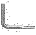
- Figure 4 is a schematic drawing and generally there would be far more plies than those shown. These may be comprised of blocks of plies (a stack of multiple plies cut to the same shape and handled together), thicknesses of 3D woven or stacked Non-Crimp-Fibre (NCF), or preforms held together by stitching, tufting or use of tackifiers. Alternatively, there could be many more single layers of unidirectional (UD) or woven material; layers of over-braiding (i.e. the casing structure is built up over a mandrel and passed though a braiding machine); or layers of filament winding (i.e. again built up on a mandrel, but in this case spun with fibre wrapping around it); or any combination of these methodologies.
- UD unidirectional
- over-braiding i.e. the casing structure is built up over a mandrel and passed though a braiding machine
- layers of filament winding i.e. again built up on a mandrel, but in this case
- the ply layup comprises one or more first plies 30 indicated by the cross-hatched portions, one or more second plies 32 indicated by the striped portions and one or more third plies 34 indicated by the blank portions.
- the ply layup further comprises resin-rich areas 36, ply drops 38 and ply butts 40.
- the ply drops 38 are located where the first plies 30 terminate and the ply butts are located where the second plies 32 abut the third plies 34.
- the first plies 30 extend over both the cylindrical portion 12 of the component and the flange portion 14.
- the second plies 32 extend over the flange portion 14 and one or more of the second plies 32 may optionally extend partially over the cylindrical portion 12 of the component. However, where the second plies 32 extend over the cylindrical portion 12 of the component, this is to a lesser extent than the first plies 30.
- the third plies 34 extend over the cylindrical portion 12 of the component and one or more of the third plies 34 may optionally extend partially over the flange portion 14. However, where the third plies 34 extend over the flange portion 14, this is again to a lesser extent than the first plies 30.
- the outermost layers of the first plies 30 cover the entire component. Inner layers of the first plies 30 may be curtailed to reduce weight.
- the outermost layers of the first plies 30 are generally the surfaces layers of the component, however additional layers may be added post-curing, such as internal liners, or surface protection layers such as anti-erosion material, or paint.
- Figure 5 shows the fibre orientation for the first plies 30.
- the first plies comprise a portion which corresponds to the cylindrical portion 12 of the component and a portion which corresponds to the flange portion 14. Over the cylindrical portion 12 of the component the fibres are oriented at 45° and thus take a helical path. Angles other than 45° may be used to vary the balance between torsional stiffness, hoop stiffness and axial stiffness. Angles may also vary on non-cylindrical shapes. These helical fibres provide torsional stiffness to the component.
- the first plies also provide protection from low energy impacts, such as from tool drops.
- the flange portion 14 also has helical fibres. When formed around the bend between the cylindrical portion 12 of the component and the flange portion 14 the fibres turn towards a circumferential or hoop orientation and thus are angled at less than 45°.
- the first plies 30 may be formed by braiding, which is a specific known method of interleaving tows or fibres. By using braiding, the first plies are formed as tubes which can follow the flange portion geometry without having a join or fold. Alternatively, the first plies may be formed by other methods of interleaving and interlocking, such as weaving or 3D weaving, knotting, felting, knitting or tatting. Filament winding is a form of 1.5D weaving, which may also be used.
- Figure 6 shows the fibre orientation for the second plies 32, over a section of the flange portion 14.
- the second plies 32 comprise radially oriented fibres 42 and circumferentially oriented fibres 44.
- the radial fibres 42 provide stiffness and strength to the flange portion 14 and the circumferential fibres provide hoop strength.
- the circumferential fibres 44 may not be necessary since, as described above, the helical fibres of the first plies 30 turn towards the circumferential or hoop orientation and thus provide hoop strength. Additional radial fibres 46 may be added at larger diameters.
- the second plies may be formed by tailored fibre placement. This is where tows of fibres are oriented in the desired directions and then stitched into place onto a backing sheet 45.
- FIG. 7 shows several layers of standard fabric, as shown in Figure 7 , having orthogonally oriented fibres.
- the layers are placed in different orientations around the flange portion 14, such that there are radially and circumferentially oriented fibres at positions around the flange portion 14 created by one of the layers.
- a larger number of layers creates an increasingly similar effect to that of tailored fibre placement, but at a lower cost.
- tailored fibre placement may be used to create a 3D shape from a flat backing sheet 45.
- the radial fibres 42 and additional radial fibres 46 may be stitched onto a flat backing sheet which is then darted to create the 3D shape.
- the section 48 is cut out from the backing sheet 45 and the cut edges are brought together to form the 3D shape shown on the right hand side of Figure 8 .
- the cut edges may be brought together by tacking the edges using glue or tackifier, or stitching the ply straight into place onto the previous layer(s).
- the circumferential fibres 44 may then be stitched onto the flange portion 14.
- filament winding or tape laying may be used to apply such a layer of fibres.
- the third plies 34 extend over the cylindrical portion 12 of the component and are required to provide the component with stiffness in both circumferential and axial directions.
- the third plies 34 may be a single layer woven fabric such as a 5 harness satin weave, which has not too much crimp but is interwoven enough to hold together during manufacturing. This is preferably wrapped around the barrel several times, so that the start and finish line of weakness is minimised.
- a multi-layer fabric may be chosen, such as a 3 or 4 ply Non Crimp Fabric (NCF).
- NCF Non Crimp Fabric
- the 0 and 90 degree fibres are virtually un-crimped, and held in place by very light interwoven fibres.
- the advantage of this material is that the material is inherently stiffer, because the crimping is eliminated, and layup is also quicker as several thicknesses of material are handled in each ply.
- the join line of weakness is more pronounced and can only be minimised over several blockings of layup.
- the material is less easily draped, making it difficult to shape it around even a part of the flange portion 14.
- a 3D woven fabric may be suited to use in a containment casing, where deflection under impact and spreading out the area of impact damage is desirable.
- 2 1 ⁇ 2 D braiding This is like 2D braiding, in that it creates a tube of material that is wrapped over a mandrel.
- axial fibres are also added, so that the tube is no longer "stretchy" (cannot be made to grow or shrink in diameter), as the axial fibres constrain it.
- the axial fibres constrain the shape so that the act of braiding creates a given shape, rather than a shape that can change by shearing of the fibres.
- the axial fibres are needed to provide axial stiffness to the cylindrical portion 12 of the component. The relative proportion of axial fibres can be chosen.
- the hoop stiffness is provided by the other fibres, which instead of being loosely braided in a very open form at a nominal 45°, they are packed at as shallow an angle as possible. In this way, they are very nearly hoop aligned, closely spaced, and braided straight into position, so the alignment and packing tolerance is good.
- filament winding may be used. This may be in combination with UD or with NCF or woven fabric with a higher tow number in the axial direction. This also has the benefit of minimising the join line problem.
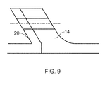
- Figure 9 shows an alternative embodiment of the invention, in which the flange portions 14 and 20 are angled. Such an arrangement allows filament winding to be used for the first plies 30.
Landscapes
- Engineering & Computer Science (AREA)
- Mechanical Engineering (AREA)
- General Engineering & Computer Science (AREA)
- Moulding By Coating Moulds (AREA)
- Laminated Bodies (AREA)
- Lining Or Joining Of Plastics Or The Like (AREA)
Applications Claiming Priority (1)
| Application Number | Priority Date | Filing Date | Title |
|---|---|---|---|
| GBGB1106794.9A GB201106794D0 (en) | 2011-04-21 | 2011-04-21 | A composite flange element |
Publications (2)
| Publication Number | Publication Date |
|---|---|
| EP2514929A2 true EP2514929A2 (fr) | 2012-10-24 |
| EP2514929A3 EP2514929A3 (fr) | 2018-01-17 |
Family
ID=44147377
Family Applications (1)
| Application Number | Title | Priority Date | Filing Date |
|---|---|---|---|
| EP12164712.7A Withdrawn EP2514929A3 (fr) | 2011-04-21 | 2012-04-19 | Elément de bride en matériau composite |
Country Status (3)
| Country | Link |
|---|---|
| US (1) | US9140140B2 (fr) |
| EP (1) | EP2514929A3 (fr) |
| GB (1) | GB201106794D0 (fr) |
Cited By (5)
| Publication number | Priority date | Publication date | Assignee | Title |
|---|---|---|---|---|
| WO2014200571A2 (fr) | 2013-02-19 | 2014-12-18 | United Technologies Corporation | Structure d'attachement composite à armure 3d |
| EP3098391A3 (fr) * | 2015-05-07 | 2017-02-22 | General Electric Company | Brides anti-cordage de bande de turbine |
| CN110821583A (zh) * | 2019-12-05 | 2020-02-21 | 中国航发四川燃气涡轮研究院 | 机匣筒体的边缘连接结构和机匣 |
| US10807322B2 (en) | 2015-04-30 | 2020-10-20 | Rolls-Royce Plc | Method of manufacturing a composite component |
| US11085316B2 (en) | 2018-08-22 | 2021-08-10 | Raytheon Technologies Corporation | Blade outer air seal formed of laminate and having radial support hooks |
Families Citing this family (27)
| Publication number | Priority date | Publication date | Assignee | Title |
|---|---|---|---|---|
| US9140135B2 (en) * | 2010-09-28 | 2015-09-22 | United Technologies Corporation | Metallic radius block for composite flange |
| GB201100585D0 (en) * | 2011-01-14 | 2011-03-02 | Magma Global Ltd | Connector arrangement for composite pipe |
| US9149997B2 (en) | 2012-09-14 | 2015-10-06 | United Technologies | Composite flange from braided preform |
| EP2883688B1 (fr) * | 2013-12-13 | 2021-09-22 | Safran Aero Boosters SA | Carter annulaire composite de compresseur de turbomachine et procédé d'obtention de celui-ci |
| EP2930316B1 (fr) | 2014-04-10 | 2021-01-27 | Safran Aero Boosters SA | Carter composite de compresseur de turbomachine axiale |
| US9796117B2 (en) | 2014-06-03 | 2017-10-24 | Gkn Aerospace Services Structures Corporation | Apparatus for forming a flange |
| US9935518B2 (en) * | 2014-08-14 | 2018-04-03 | Baker Hughes, A Ge Company, Llc | Shim free pothead housing connection to motor of electrical submersible well pump |
| BE1022462B1 (fr) * | 2014-09-12 | 2016-04-07 | Techspace Aero S.A. | Carter composite de compresseur basse pression de turbomachine axiale |
| US9937671B2 (en) * | 2016-01-15 | 2018-04-10 | Moog Inc. | All-composite torque tube with metal eyelets |
| DE102016205493A1 (de) | 2016-04-04 | 2017-10-05 | Schaeffler Technologies AG & Co. KG | Radflansch und Verfahren zur Herstellung des Radflansches |
| JP6747265B2 (ja) * | 2016-11-18 | 2020-08-26 | コニカミノルタ株式会社 | 可搬型放射線画像撮影装置 |
| CN107187074B (zh) * | 2017-07-27 | 2019-03-22 | 北京汽车集团有限公司 | 减小复合材料u型制件变形的方法 |
| EP3480479B1 (fr) * | 2017-11-01 | 2024-10-30 | Crompton Technology Group Limited | Arbre de transmission |
| EP3608092B1 (fr) * | 2018-08-10 | 2023-06-28 | Crompton Technology Group Limited | Connecteur composite et son procédé de fabrication |
| EP3608093B1 (fr) | 2018-08-10 | 2024-04-17 | Crompton Technology Group Limited | Connecteur composite et son procédé de fabrication |
| EP3608095B1 (fr) | 2018-08-10 | 2026-05-06 | Crompton Technology Group Limited | Connecteurs composites et leurs procédés de fabrication |
| EP3608091B1 (fr) | 2018-08-10 | 2025-10-01 | Crompton Technology Group Limited | Connecteur composite et son procédé de fabrication |
| EP3608094B1 (fr) | 2018-08-10 | 2024-09-25 | Crompton Technology Group Limited | Connecteur composite et son procédé de fabrication |
| EP3608089B1 (fr) | 2018-08-10 | 2022-10-12 | Crompton Technology Group Limited | Connecteur composite et son procédé de fabrication |
| EP3805623B1 (fr) | 2019-10-07 | 2023-11-29 | Crompton Technology Group Limited | Tuyaux composites en polymère renforcé de fibres et procédé de fabrication |
| RU201830U1 (ru) * | 2020-09-25 | 2021-01-14 | Общество с ограниченной ответственностью "УралАктив" | Вентилятор |
| EP4001677B1 (fr) * | 2020-11-19 | 2022-11-09 | AIRBUS HELICOPTERS DEUTSCHLAND GmbH | Arbre d'entraînement avec une bride intégré |
| RU2754054C1 (ru) * | 2020-12-23 | 2021-08-25 | Общество с ограниченной ответственностью "УралАктив" | Вентилятор |
| US20220307388A1 (en) | 2021-03-24 | 2022-09-29 | General Electric Company | Hybrid composite components |
| FR3135109B1 (fr) * | 2022-04-29 | 2024-05-24 | Safran Ceram | Anneau pour turbine de turbomachine |
| US12215592B1 (en) * | 2024-02-07 | 2025-02-04 | General Electric Company | Preform for making a casing structure for turbine engines |
| DE102024129035A1 (de) * | 2024-10-08 | 2026-04-09 | Rolls-Royce Deutschland Ltd & Co Kg | Ringförmiges Bauteil, Flugzeugtriebwerk mit einem ringförmigen Bauteil und Verfahren zur Herstellung eines ringförmigen Bauteils |
Family Cites Families (13)
| Publication number | Priority date | Publication date | Assignee | Title |
|---|---|---|---|---|
| US3298560A (en) | 1963-05-20 | 1967-01-17 | Standard Oil Co | Piping attachment means for plastic vessels |
| GB1509271A (en) | 1975-01-07 | 1978-05-04 | Oldham Seals Ltd | Hose with integral flanged end |
| GB1497107A (en) * | 1975-10-13 | 1978-01-05 | Uniroyal Ltd | Expansion joints and dredging sleeves |
| US4331723A (en) | 1980-11-05 | 1982-05-25 | The Boeing Company | Advanced composite |
| US5843355A (en) * | 1996-01-24 | 1998-12-01 | The Boeing Company | Method for molding a thermoplastic composite sine wave spar structure |
| US6520706B1 (en) | 2000-08-25 | 2003-02-18 | Lockheed Martin Corporation | Composite material support structures with sinusoidal webs and method of fabricating same |
| US7045084B1 (en) * | 2004-02-17 | 2006-05-16 | Northrop Grumman Corporation | Process for making a curved preform made from woven composite materials |
| US8079773B2 (en) * | 2005-10-18 | 2011-12-20 | General Electric Company | Methods and apparatus for assembling composite structures |
| US7871486B2 (en) | 2006-11-21 | 2011-01-18 | General Electric Company | Methods for making structures having mounting flanges |
| US7749927B2 (en) * | 2006-12-27 | 2010-07-06 | General Electric Company | Tethered corners and flanges and articles comprising the same |
| US7914256B2 (en) * | 2007-04-17 | 2011-03-29 | General Electric Company | Articles made from composite materials having toughened and untoughened regions |
| US8092164B2 (en) * | 2007-08-30 | 2012-01-10 | United Technologies Corporation | Overlap interface for a gas turbine engine composite engine case |
| US9017814B2 (en) * | 2007-10-16 | 2015-04-28 | General Electric Company | Substantially cylindrical composite articles and fan casings |
-
2011
- 2011-04-21 GB GBGB1106794.9A patent/GB201106794D0/en not_active Ceased
-
2012
- 2012-04-19 EP EP12164712.7A patent/EP2514929A3/fr not_active Withdrawn
- 2012-04-19 US US13/451,061 patent/US9140140B2/en active Active
Non-Patent Citations (1)
| Title |
|---|
| None |
Cited By (10)
| Publication number | Priority date | Publication date | Assignee | Title |
|---|---|---|---|---|
| WO2014200571A2 (fr) | 2013-02-19 | 2014-12-18 | United Technologies Corporation | Structure d'attachement composite à armure 3d |
| EP2959131A4 (fr) * | 2013-02-19 | 2016-11-09 | United Technologies Corp | Structure d'attachement composite à armure 3d |
| US10287918B2 (en) | 2013-02-19 | 2019-05-14 | United Technologies Corporation | Composite attachment structure with 3D weave |
| US10807322B2 (en) | 2015-04-30 | 2020-10-20 | Rolls-Royce Plc | Method of manufacturing a composite component |
| EP3098391A3 (fr) * | 2015-05-07 | 2017-02-22 | General Electric Company | Brides anti-cordage de bande de turbine |
| US10392950B2 (en) | 2015-05-07 | 2019-08-27 | General Electric Company | Turbine band anti-chording flanges |
| US11085316B2 (en) | 2018-08-22 | 2021-08-10 | Raytheon Technologies Corporation | Blade outer air seal formed of laminate and having radial support hooks |
| EP3613950B1 (fr) * | 2018-08-22 | 2023-09-27 | Raytheon Technologies Corporation | Joint d'air externe de lame composite et doté de crochets de support radiaux |
| CN110821583A (zh) * | 2019-12-05 | 2020-02-21 | 中国航发四川燃气涡轮研究院 | 机匣筒体的边缘连接结构和机匣 |
| CN110821583B (zh) * | 2019-12-05 | 2022-06-17 | 中国航发四川燃气涡轮研究院 | 机匣筒体的边缘连接结构和机匣 |
Also Published As
| Publication number | Publication date |
|---|---|
| US20120270006A1 (en) | 2012-10-25 |
| US9140140B2 (en) | 2015-09-22 |
| EP2514929A3 (fr) | 2018-01-17 |
| GB201106794D0 (en) | 2011-06-01 |
Similar Documents
| Publication | Publication Date | Title |
|---|---|---|
| US9140140B2 (en) | Composite flange element | |
| KR102044896B1 (ko) | 복합 팬케이스용 원주방향 보강재 | |
| JP3943572B2 (ja) | 繊維強化複合材料用プリフォーム前駆体、繊維強化複合材料用プリフォームおよびその製造方法 | |
| US10260374B2 (en) | Composite flange from braided preform | |
| CA2889366C (fr) | Carter cylindrique et procede de production de carter cylindrique | |
| CN101998905B (zh) | 用于复合结构的多向强化成形编织预成形件 | |
| EP2815084B1 (fr) | Boîtier de turbine à gaz avec chemisage balistique | |
| RU2542976C2 (ru) | Волокнистая заготовка, усиленный волокнами композитный элемент и способ их изготовления | |
| CN114341532A (zh) | 用于iv类压力容器的端部凸台 | |
| MX2012003668A (es) | Preforma tejida, material compuesto y metodo de elaboracion de los mismos. | |
| KR20120082436A (ko) | 직조 모재, 복합물 및 그 제조방법 | |
| US20240150009A1 (en) | Multi-layer braided article | |
| WO2020084946A1 (fr) | Réservoir à haute pression | |
| JP2020049860A (ja) | 繊維強化樹脂体 |
Legal Events
| Date | Code | Title | Description |
|---|---|---|---|
| PUAI | Public reference made under article 153(3) epc to a published international application that has entered the european phase |
Free format text: ORIGINAL CODE: 0009012 |
|
| AK | Designated contracting states |
Kind code of ref document: A2 Designated state(s): AL AT BE BG CH CY CZ DE DK EE ES FI FR GB GR HR HU IE IS IT LI LT LU LV MC MK MT NL NO PL PT RO RS SE SI SK SM TR |
|
| AX | Request for extension of the european patent |
Extension state: BA ME |
|
| RAP1 | Party data changed (applicant data changed or rights of an application transferred) |
Owner name: ROLLS-ROYCE PLC |
|
| PUAL | Search report despatched |
Free format text: ORIGINAL CODE: 0009013 |
|
| AK | Designated contracting states |
Kind code of ref document: A3 Designated state(s): AL AT BE BG CH CY CZ DE DK EE ES FI FR GB GR HR HU IE IS IT LI LT LU LV MC MK MT NL NO PL PT RO RS SE SI SK SM TR |
|
| AX | Request for extension of the european patent |
Extension state: BA ME |
|
| RIC1 | Information provided on ipc code assigned before grant |
Ipc: F01D 25/24 20060101AFI20171212BHEP |
|
| STAA | Information on the status of an ep patent application or granted ep patent |
Free format text: STATUS: REQUEST FOR EXAMINATION WAS MADE |
|
| 17P | Request for examination filed |
Effective date: 20180703 |
|
| RBV | Designated contracting states (corrected) |
Designated state(s): AL AT BE BG CH CY CZ DE DK EE ES FI FR GB GR HR HU IE IS IT LI LT LU LV MC MK MT NL NO PL PT RO RS SE SI SK SM TR |
|
| STAA | Information on the status of an ep patent application or granted ep patent |
Free format text: STATUS: THE APPLICATION HAS BEEN WITHDRAWN |
|
| 18W | Application withdrawn |
Effective date: 20190418 |