EP2514948B1 - Système de carburant réparti de moteur d'avion - Google Patents
Système de carburant réparti de moteur d'avion Download PDFInfo
- Publication number
- EP2514948B1 EP2514948B1 EP12162775.6A EP12162775A EP2514948B1 EP 2514948 B1 EP2514948 B1 EP 2514948B1 EP 12162775 A EP12162775 A EP 12162775A EP 2514948 B1 EP2514948 B1 EP 2514948B1
- Authority
- EP
- European Patent Office
- Prior art keywords
- fuel
- stage
- metering module
- injector
- flow
- Prior art date
- Legal status (The legal status is an assumption and is not a legal conclusion. Google has not performed a legal analysis and makes no representation as to the accuracy of the status listed.)
- Active
Links
Images


Classifications
-
- F—MECHANICAL ENGINEERING; LIGHTING; HEATING; WEAPONS; BLASTING
- F02—COMBUSTION ENGINES; HOT-GAS OR COMBUSTION-PRODUCT ENGINE PLANTS
- F02C—GAS-TURBINE PLANTS; AIR INTAKES FOR JET-PROPULSION PLANTS; CONTROLLING FUEL SUPPLY IN AIR-BREATHING JET-PROPULSION PLANTS
- F02C7/00—Features, components parts, details or accessories, not provided for in, or of interest apart form groups F02C1/00 - F02C6/00; Air intakes for jet-propulsion plants
- F02C7/22—Fuel supply systems
- F02C7/236—Fuel delivery systems comprising two or more pumps
-
- F—MECHANICAL ENGINEERING; LIGHTING; HEATING; WEAPONS; BLASTING
- F02—COMBUSTION ENGINES; HOT-GAS OR COMBUSTION-PRODUCT ENGINE PLANTS
- F02C—GAS-TURBINE PLANTS; AIR INTAKES FOR JET-PROPULSION PLANTS; CONTROLLING FUEL SUPPLY IN AIR-BREATHING JET-PROPULSION PLANTS
- F02C7/00—Features, components parts, details or accessories, not provided for in, or of interest apart form groups F02C1/00 - F02C6/00; Air intakes for jet-propulsion plants
- F02C7/22—Fuel supply systems
- F02C7/228—Dividing fuel between various burners
-
- F—MECHANICAL ENGINEERING; LIGHTING; HEATING; WEAPONS; BLASTING
- F02—COMBUSTION ENGINES; HOT-GAS OR COMBUSTION-PRODUCT ENGINE PLANTS
- F02C—GAS-TURBINE PLANTS; AIR INTAKES FOR JET-PROPULSION PLANTS; CONTROLLING FUEL SUPPLY IN AIR-BREATHING JET-PROPULSION PLANTS
- F02C9/00—Controlling gas-turbine plants; Controlling fuel supply in air- breathing jet-propulsion plants
- F02C9/26—Control of fuel supply
- F02C9/30—Control of fuel supply characterised by variable fuel pump output
-
- F—MECHANICAL ENGINEERING; LIGHTING; HEATING; WEAPONS; BLASTING
- F05—INDEXING SCHEMES RELATING TO ENGINES OR PUMPS IN VARIOUS SUBCLASSES OF CLASSES F01-F04
- F05D—INDEXING SCHEME FOR ASPECTS RELATING TO NON-POSITIVE-DISPLACEMENT MACHINES OR ENGINES, GAS-TURBINES OR JET-PROPULSION PLANTS
- F05D2270/00—Control
- F05D2270/30—Control parameters, e.g. input parameters
- F05D2270/306—Mass flow
-
- F—MECHANICAL ENGINEERING; LIGHTING; HEATING; WEAPONS; BLASTING
- F05—INDEXING SCHEMES RELATING TO ENGINES OR PUMPS IN VARIOUS SUBCLASSES OF CLASSES F01-F04
- F05D—INDEXING SCHEME FOR ASPECTS RELATING TO NON-POSITIVE-DISPLACEMENT MACHINES OR ENGINES, GAS-TURBINES OR JET-PROPULSION PLANTS
- F05D2270/00—Control
- F05D2270/30—Control parameters, e.g. input parameters
- F05D2270/31—Fuel schedule for stage combustors
Definitions
- the present disclosure relates to a fuel system for delivering fuel to a gas turbine engine.
- a typical fuel system includes a large pump driven by a turbine engine through a gearbox.
- the pump is specifically oversized for peak demand.
- the fuel system includes a bypass valve to return unneeded fuel back to the engine fuel inlet or fuel tank, which is inefficient.
- the fuel returned to the tank is hot, which undesirably raises the temperature of fuel in the fuel tank.
- excess pressure is generated that must be relieved by using a pressure relief valve to mitigate any potential burst or over pressure conditions.
- fuel injectors are arranged into operative groups called "stages".
- stages a single engine-driven pump and metering valve feed fuel to a plurality of fuel distribution lines.
- Each fuel distribution line includes a staging valve for modulating fuel flow to a single combustor stage, which includes a plurality of fuel injectors.
- Some fuel systems additionally include temperature sensors proximate the fuel injectors to monitor temperature distribution around the combustor.
- US 2003/136105 A1 discloses a fuel flow system for a gas turbine engine.
- the fuel flow system includes a first branch that supplies fuel to first stage fuel injectors and a second branch which supplies fuel to second stage fuel injectors.
- Each branch includes a pumping assembly that transmits fuel to the corresponding combustor fuel injector stage, and the pumping assemblies are each controlled by an associated variable-speed drive motor.
- a scheduling computer separately controls each of the drive motors, thereby permitting the pumping assemblies to operate independently.
- a first aspect of the invention provides a fuel system for a gas turbine engine having an electronic engine control, the fuel system comprising: a plurality of fuel injectors grouped by stages in a multistage combustor, each stage comprising a plurality of fuel injectors; and at least one fuel flow metering module per stage of the multistage combustor, wherein the plurality of fuel flow metering modules are configured to control fuel output to one or more fuel injectors in the multistage combustor, wherein the plurality of fuel flow metering modules are configured to operate independently of one another, and wherein each fuel flow metering module includes: a positive displacement pump for pumping fuel; and an electric motor for driving the positive displacement pump, characterised in that each fuel flow metering module comprises: a flow meter for measuring fuel flow; a first pressure sensor for sensing fuel pressure; and a controller for receiving and analyzing information regarding fuel flow from the flow meter, fuel pressure from the first pressure sensor, and fuel demand from the electronic engine control; and in that the electric motor is oper
- a second aspect of the invention provides a method for distributing fuel in a gas turbine engine using the fuel system as mentioned above and having a fuel requirement, the method comprising: pumping fuel to at least one fuel injector of a multistage combustor; measuring flow rate of fuel while pumping fuel; sensing and analyzing fuel pressure; comparing the measured flow rate of fuel with the gas turbine engine fuel requirement; and controlling pumping speed based on the comparison between the measured flow rate of fuel and the gas turbine engine fuel requirement to modulate fuel flowing to the at least one fuel injector of the multistage combustor.
- Fig. 1A is a side schematic view of gas turbine engine 10 having multistage combustor 12, and Fig. 1B is a cross section of multistage combustor 12.
- Gas turbine engine 10 includes fan 14, low pressure compressor (LPC) 16, high pressure compressor (HPC) 18, high pressure turbine (HPT) 20, and low pressure turbine (LPT) 22.
- Multistage combustor 12 includes first stage fuel injectors 24 and second stage fuel injectors 26 located within fuel nozzles 28.
- gas turbine engine 10 is a turbofan engine for powering an aircraft, although the invention is not so limited and can be utilized in any gas turbine engine.
- LPC 16 Located within gas turbine engine 10 and arranged in flow series are fan 14, LPC 16, HPC 18, multistage combustor 12, HPT 20, and LPT 22.
- LPC 16 is mechanically coupled to LPT 22 by a low pressure shaft and HPC 18 is mechanically coupled to HPT 20 by a high pressure shaft.
- air enters a front end of gas turbine engine 10 at fan 14 and is compressed by LPC 16 and HPC 18. The compressed air then enters multistage combustor 12, where it is mixed with fuel and combusted. Combusted air enters HPT 20 and LPT 22 where it is expanded and forces one or both of the turbines to rotate, which drives fan 14, LPC 16 and HPC 18.
- First stage fuel injectors 24 may be physically coupled with second stage fuel injectors 26, such that one first stage fuel injector 24 and one second stage fuel injector 26 form a single fuel nozzle 28.
- a number of fuel nozzles 28 are located around multistage combustor 12.
- the depicted embodiment includes four first stage fuel injectors 24 and four second stage fuel injectors 26 coupled together to form four fuel nozzles 28. More than two fuel injector stages are possible, as are more or less fuel nozzles 28.
- First stage fuel injectors 24 spray fuel into multistage combustor 12 either jointly as a first stage operative group, or independently as individual injectors.
- second stage fuel injectors 26 spray fuel into multistage combustor 12 either jointly as a second stage operative group or independently as individual injectors. Fuel flow and control is discussed further below with respect to Figs. 2-5 .
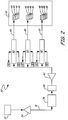
- Fig. 2 is a block diagram showing a first embodiment of fuel distribution system 30 for multistage combustor 12.
- Fuel distribution system 30 includes tank 32, first boost pump 34, fuel/oil heat exchanger (FOHE) 36, filter 38, second boost pump 40, main conduit 41, fuel flow metering modules (FFMMs) 42, first stage conduit 43, first stage fuel injectors 44, second stage conduit 45, second stage fuel injectors 46, third stage conduit 47, and third stage fuel injectors 48. Also shown in Fig. 2 are electric power 50 input and central control 52 input/output for each FFMM 42. Fuel distribution system 30 has one FFMM 42 for each stage of fuel injectors (44, 46, and 48) to provide a distributed, on-demand fuel supply to each stage of a multistage combustor in a gas turbine engine.
- FHE fuel/oil heat exchanger
- Fuel tank 32, first boost pump 34, FOHE 36, filter 38, and second boost pump 40 are positioned in flow series along main conduit 41.
- Fuel such as jet fuel
- First boost pump 34 is located downstream of fuel tank 32 on main conduit 41 and pulls fuel from tank 32 along main conduit 41.
- first boost pump 34 is a gearbox driven boost pump that receives rotational input from the gas turbine engine 10.
- first boost pump 34 is electrical.
- FOHE 36 is located downstream of first boost pump 34 on main conduit 41. Within FOHE 36, heat from the engine oil system is commonly rejected to the fuel passing through FOHE 36.
- Filter 38 is located downstream of FOHE 36 on main conduit 41.
- Second boost pump 40 is an optional, additional pump for fuel system 30 located downstream of filter 38 on main conduit 41.
- a fuel pressure sensor is optionally located downstream of second boost pump 40, on main conduit 41 to sense fuel pressure before fuel flows into the branch conduits.
- main conduit 41 splits into three branch conduits corresponding to the three stages of multistage combustor 12: first stage conduit 43, second stage conduit 45, and third stage conduit 47. It should be appreciated that more or less stages, as well as more or less fuel injectors per stage, are possible.
- Each branch conduit 43, 45, 47 includes its own FFMM 42 located between main conduit 41 and fuel injectors 44, 46, 48 in multistage combustor 12. A first portion of fuel flows through first FFMM 42 located on first stage conduit 43 to supply first stage fuel injectors 44. A second portion of fuel flows through second FFMM 42 located on second stage conduit 45 to supply second stage fuel injectors 46.
- a third portion of fuel flows through third FFMM 42 located on third stage conduit 47 to supply third stage fuel injectors 48.
- Each FFMM 42 has an input for electric power 50, and both an input and an output for central control 52. Incoming information is received from, and outgoing information is sent to, central control 52.
- central control 52 is a full-authority digital electronic engine control (FADEC).
- FADEC full-authority digital electronic engine control
- Each FFMM 42 exchanges information with central control 52 to independently modulate fuel flow to a plurality of fuel injectors operatively forming single stage of the multistage combustor.
- a single FFMM 42 is shown and described in detail below with respect to Fig. 3 .
- Fig. 3 is block diagram of first FFMM 42 on first stage conduit 43 associated with first stage injectors 44. Input from energy source 50 and input/output to central control 52 are shown. Also depicted are the components of FFMM 42: pump 54, flow meter 56, first sensor 58, controller 60, and motor 62. Additional second sensor 64 is operationally associated with FFMM 42, but located in multistage combustor 12. First FFMM 42 controls a first portion of fuel flow along first stage conduit 43 to first stage fuel injectors 44, but the discussion below applies generally to all FFMMs 42 described herein.
- pump 54 is a positive displacement pump, which pumps fuel to first stage fuel injectors 44.
- Flow meter 56 is located either downstream or upstream of pump 54, and measures the flow rate of fuel as it flows through pump 54 (mass flow meter or density and volume flow meter).
- First sensor 58 is located downstream of pump 54 and flow meter 56, and measures the pressure of fuel before it exits FFMM 42 and is sent to first stage fuel injectors 44.
- Second sensor 64 is located downstream of first stage fuel injectors 44 in multistage combustor 12, and measures the gas pressure of the combustor 12.
- the sensed flow rate is sent from flow meter 56 to controller 60, and the sensed pressures are sent from first sensor 58 and second sensor 64 to controller 60.
- Controller 60 receives the sensed flow rate from flow meter 56, the sensed pressures from first sensor 58 and second sensor 64, as well as power 50 and information from central control 52.
- motor 62 is a simplex permanent magnet variable speed electric motor that drives fuel pump 54 at a speed determined by controller 60. Controller 60 modulates the speed of motor 62 based on a combination of information received from flow meter 56, and central control 52.
- First sensor 58 and second sensor 64 (as well as an optional fuel pressure sensor located upstream of first stage conduit 43) are used for monitoring the health of the system.
- central control 52 sends a signal to controller 60 indicating fuel demand for first stage fuel injectors 44 of the multistage combustor. Controller 60 then indicates speed of motor 62 based on desired fuel demand from central control 52. Motor 62 drives pump 54 at the indicated speed, and fuel is sent through flow meter 56, past first sensor 58, and out of first stage fuel injectors 44 into the multistage combustor 12. Information regarding fuel flow from flow meter 56 and pressure from first sensor 58 and second sensor 64 provide feedback to controller 60 regarding fuel flow, fuel pressure, and combustor pressure. The sensed or actual mass flow rate from flow meter 56 is compared to desired fuel flow or demand from control 52 to better modulate the output of pump 54 (via motor 62 speed).
- first sensor 58 and second sensor 64 are used to detect clogging of first stage fuel injectors 44.
- speed of motor 62 is monitored to detect pump 54 wear.
- the pump/motor speed required to produce the necessary flow at a given combination of first sensor pressure and second sensor pressure is compared to recorded values for the new pump to determine the extent of pump wear. If excessive wear is detected, a maintenance message is sent to the central control 52.
- the information gathered by controller 60, including the health of various components, is sent to central control 52.
- central control 52 When the gas turbine engine is in use, fuel demand is calculated by central control 52. At aircraft takeoff, there is a large fuel demand and central control 52 will activate each stage of the multistage combustor 12 in the proper sequence. In comparison, at cruising altitude, there is less fuel demand and central control 52 will only activate certain stages of the multistage combustor.
- the present disclosure provides a distributed, on-demand fuel system that negates the need for problematic modulating staging valves. FFMMs 42 can be activated by central control 52 with variable overlap to fill fuel conduits before fuel flow is needed from the injectors, thereby accounting for "line fill" delays.
- This line filling can be accomplished by momentarily pumping fuel to fill the line at the maximum flow capability of the pump and simultaneously monitoring motor current to detect filling. Interaction between stages, which can occur when one pump is supplying multiple staging valves is avoided through use of FFMMs 42. A failure in one stage of the multistage fuel system can be detected and remaining stages can be adjusted to compensate for the failure. Additionally, fuel heating is reduced since only the fuel required for combustion is pumped through FOHE 36, thereby enabling greater heat sink capability. Individual control over each fuel flow output by FFMM 42 provides the ability to tailor fuel flow split between each fuel flow output. In an electrically driven demand fuel system with one pump, a dual redundant motor is required to handle the case of a motor failure during flight. This doubles the motor weight on the engine. In the configuration described in this disclosure, redundant motors are not required since a failure of one motor would not stop engine fuel flow and would only have a small impact on the overall engine fuel flow depending on how many pumping systems are incorporated.
- Fig. 4 is a block diagram showing a second embodiment of fuel distribution system 30' for multistage combustor 12'.
- Fuel distribution system 30' is substantially similar to fuel distribution system 30 described above with reference to Fig. 2 , and like reference numerals designate like components.
- Fuel distribution system 30' includes tank 32, first boost pump 34, FOHE 36, filter 38, second boost pump 40, main conduit 41, fuel flow metering modules (FFMMs) 42, electric power 50 input, and central control 52 input/output. Also shown in Fig. 4 are first injector conduit 65, first injector 66, second injector conduit 67, second injector 68, third injector conduit 69, third injector 70, fourth injector conduit 71, and fourth injector 72.
- FFMMs fuel flow metering modules
- the second embodiment of fuel distribution system 30' has one FFMM 42 for each fuel injector 66, 68, 70, 72 to provide a distributed, on-demand fuel supply to each injector 66, 68, 70, 72 of multistage combustor 12' in a gas turbine engine.
- Fuel tank 32, first boost pump 34, FOHE 36, filter 38, second boost pump 40, main conduit 41, FFMMs 42, electric power 50 input, and central control 52 input/output operate in the second embodiment of fuel distribution system 30' identically to the first embodiment of fuel distribution system 30 described above with reference to Fig. 2 .
- first boost pump 34 FOHE 36
- filter 38 second boost pump 40
- main conduit 41 main conduit 41
- FFMMs 42 electric power 50 input, and central control 52 input/output
- main conduit 41 splits into four branch conduits corresponding to four individual fuel injectors 66, 68, 70, 72 of multistage combustor 12: first injector conduit 65, second injector conduit 67, third injector conduit 69, and fourth injector conduit 71. It should be appreciated that more or fewer fuel injectors are equally possible.
- Each branch conduit 65, 67, 69, and 71 includes its own FFMM 42 located between main conduit 41 and individual fuel injector 66, 68, 70, and 72. A first portion of fuel flows through first FFMM 42 located on first injector conduit 65 to supply a single, first fuel injector 66.
- each fuel injector 66, 68, 70, and 72 includes its own FFMM 42 on its own feed conduit 65, 67, 69, and 71.
- the second embodiment of fuel distribution system 30' provides even greater independence of fuel distribution since each FFMM 42 controls fuel flow to a single fuel injector 66, 68, 70, 72.
- Fuel injectors 66, 68, 70, and 72 can be coupled in a single fuel nozzle or located in different fuel nozzles within multistage combustor 12'.
- the second embodiment of fuel distribution system 30' is particularly advantageous for controlling heat distribution around the combustor, known as "combustor pattern factor", by accurately and independently controlling fuel flow to each fuel injector.
- Fig. 5 is a block diagram showing a third embodiment of fuel distribution system 30.
- Fuel distribution system 30" is substantially similar to fuel distribution system 30' described above with reference to Fig. 4 and fuel distribution system 30 described above with reference to Fig. 2 , and like reference numerals designate like components.
- Fuel distribution system 30" includes tank 32, first boost pump 34, FOHE 36, filter 38, second boost pump 40, main conduit 41, fuel flow metering modules (FFMMs) 42A-42D, electric power 50 input, and central control 52 input/output. Also shown in Fig.
- FFMMs fuel flow metering modules
- Fuel distribution system 30" has two FFMM 42 for each stage of multistage combustor 12" to provide a distributed, on-demand fuel supply to the two stages of multistage combustor 12" in a gas turbine engine.
- Fuel tank 32, first boost pump 34, FOHE 36, filter 38, second boost pump 40, main conduit 41, FFMMs 42, electric power 50 input, and central control 52 input/output operate in the third embodiment of fuel distribution system 30" identically to the second embodiment of fuel distribution system 30' described above with reference to Fig. 4 and first embodiment of fuel distribution system 30 described above with reference to Fig. 2 .
- first boost pump 34 FOHE 36
- second boost pump 40 main conduit 41
- FFMMs 42 electric power 50 input, and central control 52 input/output
- main conduit 41 splits into four branch conduits corresponding to four FFMMs 42A-42D.
- Each FFMM 42A-42D is located between main conduit 41 and multistage combustor 12" and controls fuel supply for half of a stage of multistage combustor 12" (two of four fuel injectors operatively grouped into a stage). It should be appreciated that more or less FFMMs 42, as well as more or less stages, fuel injectors per stage, and fuel nozzles are equally possible.
- First stage injector 74 and second stage injector 76 are located in a first spray nozzle, while first stage injector 82 and second stage injector 84 are located in a second spray nozzle.
- a first portion of fuel flows through first FFMM 42A located on branch conduit 73. Downstream of FFMM 42A, branch conduit 73 feeds fuel to first stage injector 74, and branch conduit 81 splits off from branch conduit 73 to feed fuel to first stage injector 82 located in a different spray nozzle.
- a second portion of fuel flows through second FFMM 42B located on branch conduit 75. Downstream of FFMM 42B, branch conduit 75 feeds fuel to second stage injector 76, and branch conduit 83 splits off from branch conduit 75 to feed fuel to second stage injector 84 located in a different spray nozzle.
- First stage injector 78 and second stage injector 80 are located in a third spray nozzle, while first stage injector 86 and second stage injector 88 are located in a fourth spray nozzle.
- a third portion of fuel flows through third FFMM 42C located on branch conduit 85. Downstream of FFMM 42C, branch conduit 85 feeds fuel to first stage injector 86, and branch conduit 77 splits off from branch conduit 85 to feed fuel to first stage injector 78 located in a different spray nozzle.
- a fourth portion of fuel flows through fourth FFMM 42D located on branch conduit 87. Downstream of FFMM 42D, branch conduit 87 feeds fuel to second stage injector 88, and branch conduit 79 splits off from branch conduit 87 to feed fuel to second stage injector 80 located in a different spray nozzle.
- fuel flow to the first stage of multistage combustor 12" (including fuel injectors 74, 78, 82, and 86) is controlled equally by two FFMMs 42A and 42C.
- fuel flow to the second stage of multistage combustor 12" (including fuel injectors 76, 80, 84, and 88) is controlled equally by two FFMMs 42B and 42D.
- This third embodiment of fuel distribution system 30" is a middle ground between the first embodiment of fuel distribution system 30 (one FFMM per stage) and the second embodiment of fuel distribution system 30' (one FFMM per fuel injector) in that each FFMM 42 controls fuel flow to half of a stage of multistage combustor 12" (e.g.
- Fuel distribution system 30" results in improved thermal management and engine efficiency. Further, fuel distribution system 30" can accommodate for failure of any one FFMM 42 and therefore, redundant motor or pumping architectures are not required.
Landscapes
- Engineering & Computer Science (AREA)
- Chemical & Material Sciences (AREA)
- Combustion & Propulsion (AREA)
- Mechanical Engineering (AREA)
- General Engineering & Computer Science (AREA)
- Feeding And Controlling Fuel (AREA)
Claims (14)
- Système de carburant (30 ; 30' ; 30") pour une turbine à gaz (10) ayant une régulation de moteur électronique (52), le système de carburant comprenant :une pluralité d'injecteurs de carburant (24, 26 ; 44, 46 ; 66, 68 ; 74, 76, 78, 80, 82, 84, 86, 88) groupés par étages dans une chambre de combustion à étages multiples (12), chaque étage comprenant une pluralité d'injecteurs de carburant ; et au moins un module de dosage de débit de carburant (42 ; 42A-D) par étage de la chambre de combustion à étages multiples,dans lequel la pluralité de modules de dosage de débit de carburant sont configurés pour réguler la sortie de carburant vers un ou plusieurs injecteurs de carburant dans la chambre de combustion à étages multiples,dans lequel la pluralité de modules de dosage de débit de carburant sont configurés pour fonctionner indépendamment les uns des autres, etdans lequel chaque module de dosage de débit de carburant inclut :une pompe à déplacement positif (54) pour pomper le carburant ; etun moteur électrique (62) pour entraîner la pompe à déplacement positif (54), caractérisé en ce que chaque module de dosage de débit de carburant (42 ; 42A-D) comprend :un débitmètre (56) pour mesurer le débit de carburant ;un premier capteur de pression (58) pour détecter la pression de carburant ; etun régulateur (60) pour recevoir et analyser des informations concernant le débit de carburant provenant du débitmètre, la pression de carburant provenant du premier capteur de pression, et la demande en carburant provenant de la régulation de moteur électronique ;et en ce que le moteur électrique (62) est conçu pour entraîner la pompe à déplacement positif (54) en fonction d'un signal reçu du régulateur (60) pour moduler la sortie de carburant pour le module de dosage de débit de carburant.
- Système de carburant selon la revendication 1, comprenant en outre :un réservoir de carburant (32) ;une pompe de suralimentation (34) en aval du réservoir de carburant ;un échangeur de chaleur carburant/huile (36) en aval de la pompe de suralimentation ; etun filtre (38) en aval de l'échangeur de chaleur carburant/huile ;dans lequel ladite chambre de combustion à étages multiples (12) est en aval du filtre,et dans lequel ladite pluralité de modules de dosage de débit de carburant (42 ; 42A-D) sont situés en aval du filtre et en amont de la chambre de combustion à étages multiples.
- Système de carburant selon la revendication 1 ou 2, dans lequel la pompe à déplacement positif (54) est située en aval de la pompe de suralimentation (34) et en amont de l'au moins un injecteur de carburant.
- Système de carburant selon l'une quelconque des revendications précédentes, dans lequel le débitmètre (56) mesure le débit de carburant par l'intermédiaire de la pompe à déplacement positif (54).
- Système de carburant selon l'une quelconque des revendications précédentes, dans lequel le premier capteur de pression (58) détecte la pression de carburant en aval de la pompe à déplacement positif (54).
- Système de carburant selon l'une quelconque des revendications précédentes, comprenant en outre :
un second capteur de pression (64) pour détecter la pression de la chambre de combustion près d'au moins un injecteur de carburant. - Système de carburant selon l'une quelconque des revendications précédentes, dans lequel l'au moins un module de dosage de débit de carburant (42) par étage de la chambre de combustion à étages multiples (12) comprend :un premier module de dosage (42) situé sur un premier conduit de répartition de carburant (43) pour réguler une première sortie de carburant vers une première pluralité d'injecteurs de carburant (44) comprenant un premier étage entier de la chambre de combustion à étages multiples ; etun second module de dosage (42) sur un second conduit de répartition de carburant (45) pour réguler la seconde sortie de carburant vers une seconde pluralité d'injecteurs de carburant (46) comprenant un second étage entier de la chambre de combustion à étages multiples, dans lequel le fonctionnement du premier module de dosage est indépendant du fonctionnement du second module de dosage.
- Système de carburant selon l'une quelconque des revendications 1 à 6, dans lequel l'au moins un module de dosage de débit de carburant par étage de la chambre de combustion à étages multiples (12) comprend :un premier module de dosage (42A) sur un premier conduit (73) pour réguler une première sortie de carburant vers une première pluralité d'injecteurs carburant (72, 82) comprenant une première partie supérieure à un injecteur unique d'un premier étage de la chambre de combustion à étages multiples ; etun second module de dosage (42B) sur un second conduit (75) pour réguler une seconde sortie de carburant vers une seconde pluralité d'injecteurs de carburant (76, 84) comprenant une seconde partie du premier étage de la chambre de combustion à étages multiples, dans lequel le fonctionnement du premier module de dosage est indépendant du fonctionnement du second module de dosage.
- Système de carburant selon l'une quelconque des revendications 1 à 6, dans lequel l'au moins un module de dosage de débit de carburant (42) par étage de la chambre de combustion à étages multiples (12) comprend :un premier module de dosage sur un premier conduit (65) pour réguler une première sortie de carburant vers un premier et unique injecteur de carburant (66) ; etun second module de dosage sur un second conduit (67) pour réguler une seconde sortie de carburant vers un second etunique injecteur de carburant (68), dans lequel le fonctionnement du premier module de dosage est indépendant du fonctionnement du second module de dosage.
- Système de carburant selon la revendication 9, dans lequel le premier injecteur de carburant (66) et le second injecteur de carburant (68) sont situés dans la même buse de carburant de la chambre de combustion à étages multiples (12).
- Système de carburant selon l'une quelconque des revendications précédentes, comprenant en outre :
un capteur de pression (64) situé dans la chambre de combustion à étages multiples (12). - Procédé de répartition de carburant dans une turbine à gaz (10) à l'aide du système de carburant selon l'une quelconque des revendications précédentes et ayant un besoin en carburant, le procédé comprenant :le pompage de carburant vers l'au moins un injecteur de carburant (24, 26 ; 44, 46 ; 66, 68 ; 74, 76, 78, 80, 82, 84, 86, 88) de la chambre de combustion à étages multiples (12) ;la mesure du débit de carburant lors du pompage du carburant ;la détection et l'analyse de la pression de carburant ;la comparaison du débit de carburant mesuré au besoin en carburant de la turbine à gaz; etla régulation de la vitesse de pompage sur la base de la comparaison entre le débit de carburant mesuré et le besoin en carburant de la turbine à gaz pour moduler l'écoulement de carburant vers l'au moins un injecteur de carburant de la chambre de combustion à étages multiples.
- Procédé selon la revendication 12, comprenant en outre :la détection d'une première pression de carburant avant le pompage de carburant sur l'au moins un injecteur de carburant ; etla détection d'une seconde pression de carburant après le pompage de carburant sur l'au moins un injecteur de carburant ;comprenant en outre de préférence la mesure de la vitesse de pompage et de l'augmentation de pression de la pompe pour détecter l'usure.
- Procédé selon la revendication 12 ou 13, comprenant en outre :la pulvérisation de carburant hors de l'au moins un injecteur de carburant ; etla détection de pression de la chambre de combustion.
Applications Claiming Priority (1)
| Application Number | Priority Date | Filing Date | Title |
|---|---|---|---|
| US13/090,412 US8666632B2 (en) | 2011-04-20 | 2011-04-20 | Distributed aircraft engine fuel system |
Publications (3)
| Publication Number | Publication Date |
|---|---|
| EP2514948A2 EP2514948A2 (fr) | 2012-10-24 |
| EP2514948A3 EP2514948A3 (fr) | 2017-04-12 |
| EP2514948B1 true EP2514948B1 (fr) | 2018-05-02 |
Family
ID=46000775
Family Applications (1)
| Application Number | Title | Priority Date | Filing Date |
|---|---|---|---|
| EP12162775.6A Active EP2514948B1 (fr) | 2011-04-20 | 2012-03-30 | Système de carburant réparti de moteur d'avion |
Country Status (3)
| Country | Link |
|---|---|
| US (1) | US8666632B2 (fr) |
| EP (1) | EP2514948B1 (fr) |
| CA (1) | CA2769809A1 (fr) |
Families Citing this family (50)
| Publication number | Priority date | Publication date | Assignee | Title |
|---|---|---|---|---|
| US8578763B2 (en) * | 2011-06-22 | 2013-11-12 | Hamilton Sundstrand Corporation | System and method for fuel system health monitoring |
| US8951021B2 (en) | 2013-01-18 | 2015-02-10 | General Electric Company | Dual pump/dual bypass fuel pumping system |
| US9091212B2 (en) | 2013-03-27 | 2015-07-28 | Hamilton Sundstrand Corporation | Fuel and actuation system for gas turbine engine |
| US9618913B2 (en) * | 2013-04-29 | 2017-04-11 | Hamilton Sundstrand Corporation | Self powered fluid metering units |
| GB201313140D0 (en) * | 2013-07-23 | 2013-09-04 | Rolls Royce Engine Control Systems Ltd | System for performing staging control of a multi-stage combustor |
| US10294866B2 (en) * | 2013-11-20 | 2019-05-21 | Woodward, Inc. | Parallel metering pressure regulation system with integrated flow meter placement |
| US10443851B2 (en) | 2013-12-19 | 2019-10-15 | United Technologies Corporation | Self-pumping fuel injector for a gas turbine engine and method of operation |
| EP2889467B1 (fr) * | 2013-12-30 | 2016-09-28 | Rolls-Royce Corporation | Diviseur de débit de carburant et système de surveillance de la santé d'un système de carburant d'une turbine à gaz |
| US9631814B1 (en) | 2014-01-23 | 2017-04-25 | Honeywell International Inc. | Engine assemblies and methods with diffuser vane count and fuel injection assembly count relationships |
| US9714741B2 (en) * | 2014-02-20 | 2017-07-25 | Pcs Ferguson, Inc. | Method and system to volumetrically control additive pump |
| FR3018561B1 (fr) * | 2014-03-12 | 2017-05-26 | Ge Energy Products France Snc | Procede de controle du fonctionnement de vannes d'un dispositif d'alimentation en gaz de turbine a gaz |
| US9624835B2 (en) | 2014-07-24 | 2017-04-18 | Hamilton Sundstrand Corporation | Ecology fuel return systems |
| US10399690B2 (en) | 2014-07-24 | 2019-09-03 | Hamilton Sundstrand Corporation | Ecology fuel return systems |
| FR3033421B1 (fr) * | 2015-03-04 | 2018-05-18 | Airbus Operations | Dispositif pour generer un ecoulement d'un liquide avec un debit regule |
| US9982602B2 (en) | 2015-04-15 | 2018-05-29 | Hamilton Sundstrand Corporation | Shut off valves and components thereof for ecology fuel return systems |
| US12078110B2 (en) * | 2015-11-20 | 2024-09-03 | Us Well Services, Llc | System for gas compression on electric hydraulic fracturing fleets |
| EP3179077B1 (fr) * | 2015-12-11 | 2018-09-12 | Airbus Operations, S.L. | Système de commande de carburant pour un moteur à turbine à gaz d'aéronef |
| US10094298B2 (en) | 2015-12-15 | 2018-10-09 | Hamilton Sunstrand Corporation | Ecology system ejector pump shutoff valve |
| US11008115B2 (en) | 2017-05-09 | 2021-05-18 | Gulfstream Aerospace Corporation | Fuel system for an aircraft |
| US11485513B2 (en) | 2018-10-05 | 2022-11-01 | Parker-Hannifin Corporation | Fuel pump override control method |
| RU2698584C1 (ru) * | 2018-10-29 | 2019-08-28 | федеральное государственное бюджетное образовательное учреждение высшего образования "Пензенский государственный аграрный университет" | Двухтопливная система автотранспортного средства с регулируемым подогревом растительного масла |
| CN109625297A (zh) * | 2018-12-11 | 2019-04-16 | 石家庄飞机工业有限责任公司 | 一种用于小型通用飞机的燃油系统 |
| US11125169B2 (en) | 2018-12-19 | 2021-09-21 | General Electric Company | Fuel system for heat engine |
| FR3094749B1 (fr) * | 2019-04-03 | 2021-11-19 | Safran Nacelles | Système de refroidissement de turboréacteur pour aéronef |
| US11603802B2 (en) | 2019-08-27 | 2023-03-14 | Pratt & Whitney Canada Corp. | Methods and systems for starting a gas turbine engine |
| US11203978B2 (en) * | 2020-01-20 | 2021-12-21 | Hamilton Sundstrand Corporation | Dual pump unit with boost pump |
| US11629652B2 (en) * | 2020-02-05 | 2023-04-18 | Hamilton Sundstrand Corporation | Metering pump system |
| DE102020123120A1 (de) * | 2020-09-04 | 2022-03-10 | J. Wagner Gmbh | Betriebsverfahren für eine Fördervorrichtung mit einer Exzenterschneckenpumpe zum Fördern von zähflüssigen Baumaterialien |
| RU2753207C1 (ru) * | 2020-10-14 | 2021-08-12 | Федеральное Автономное Учреждение "Центральный институт авиационного моторостроения имени П.И. Баранова" | Система подачи топлива в многоколлекторную камеру сгорания |
| CN112780416A (zh) * | 2021-01-29 | 2021-05-11 | 安徽应流航空科技有限公司 | 一种主燃油分配结构 |
| CN113483357B (zh) * | 2021-07-06 | 2022-06-21 | 中国人民解放军国防科技大学 | 一种固定压力变位置的气体燃料喷注系统 |
| US11988158B2 (en) * | 2021-07-19 | 2024-05-21 | Pratt & Whitney Canada Corp. | Multi-fuel engine for an aircraft |
| US20230021491A1 (en) * | 2021-07-23 | 2023-01-26 | Hamilton Sundstrand Corporation | Displacement pump pressure feedback control and method of control |
| US12031492B2 (en) | 2021-10-12 | 2024-07-09 | Hamilton Sundstrand Corporation | Electric fuel control closed loop aircraft fuel system |
| US12454915B2 (en) | 2022-08-26 | 2025-10-28 | Hamilton Sundstrand Corporation | Force modification of passive valve spools for control of nozzles |
| US11913381B1 (en) | 2022-08-26 | 2024-02-27 | Hamilton Sundstrand Corporation | Force modification of passive spool for control of secondary nozzle circuits |
| US11913382B1 (en) | 2022-08-26 | 2024-02-27 | Hamilton Sundstrand Corporation | Variable restriction of a fuel circuit of a fuel nozzle |
| US12305581B2 (en) | 2022-08-26 | 2025-05-20 | Collins Engine Nozzles, Inc. | Proportional restriction of a secondary circuit of a fuel injector |
| US11970976B2 (en) | 2022-08-26 | 2024-04-30 | Hamilton Sundstrand Corporation | Variable restriction of fuel nozzle with an auxiliary circuit |
| US12270343B2 (en) | 2022-08-26 | 2025-04-08 | Collins Engine Nozzles, Inc. | Proportional restriction of fuel nozzle with an auxiliary circuit |
| US11970977B2 (en) | 2022-08-26 | 2024-04-30 | Hamilton Sundstrand Corporation | Variable restriction of a secondary circuit of a fuel injector |
| US12286931B2 (en) | 2022-08-26 | 2025-04-29 | Collins Engine Nozzles, Inc. | Variable restriction of a fuel circuit of a fuel nozzle |
| US12313004B2 (en) | 2022-08-26 | 2025-05-27 | Collins Engine Nozzles, Inc. | Proportional force modification of passive spool for control of secondary nozzle circuits |
| GB202219384D0 (en) | 2022-12-21 | 2023-02-01 | Rolls Royce Plc | Aircraft fuelling |
| GB202219383D0 (en) * | 2022-12-21 | 2023-02-01 | Rolls Royce Plc | Combustion management |
| GB202219406D0 (en) * | 2022-12-21 | 2023-02-01 | Rolls Royce Plc | Aircraft fuel system |
| GB202219381D0 (en) * | 2022-12-21 | 2023-02-01 | Rolls Royce Plc | Gas turbine fuel delivery |
| GB202219385D0 (en) | 2022-12-21 | 2023-02-01 | Rolls Royce Plc | Aircraft combustion systems |
| GB202219380D0 (en) | 2022-12-21 | 2023-02-01 | Rolls Royce Plc | Gas turbine operating conditions |
| US12398681B2 (en) * | 2023-09-13 | 2025-08-26 | Rtx Corporation | Built-in test of actively controlled fuel nozzles |
Family Cites Families (11)
| Publication number | Priority date | Publication date | Assignee | Title |
|---|---|---|---|---|
| GB0023727D0 (en) | 2000-09-27 | 2000-11-08 | Lucas Industries Ltd | Control system |
| US6655151B2 (en) * | 2001-09-07 | 2003-12-02 | Honeywell International, Inc. | Method for controlling fuel flow to a gas turbine engine |
| US6637184B2 (en) * | 2002-01-24 | 2003-10-28 | Siemens Westinghouse Power Corporation | Flow control system for liquid fuel engine having stage-specific control of fuel flow to several groups of nozzles in the engine |
| US7137613B2 (en) | 2002-02-28 | 2006-11-21 | Jansen's Aircraft Systems Controls, Inc. | Pattern factor control valve |
| US6996970B2 (en) * | 2003-09-30 | 2006-02-14 | Honeywell International Inc. | High accuracy fuel metering system for turbine engines |
| EP1524423A1 (fr) | 2003-10-13 | 2005-04-20 | Siemens Aktiengesellschaft | Procédé et dispositif pour niveler la fluctuation de la composition du carburant dans une turbine à gaz |
| US7845177B2 (en) | 2004-09-16 | 2010-12-07 | Hamilton Sundstrand Corporation | Metering demand fuel system |
| US7216487B2 (en) * | 2004-09-16 | 2007-05-15 | Hamilton Sundstrand | Metering demand fuel system for gas turbine engines |
| JP4499643B2 (ja) | 2005-09-30 | 2010-07-07 | 日立オートモティブシステムズ株式会社 | 多段燃料噴射式内燃機関 |
| US7654092B2 (en) | 2006-07-18 | 2010-02-02 | Siemens Energy, Inc. | System for modulating fuel supply to individual fuel nozzles in a can-annular gas turbine |
| US20090077945A1 (en) * | 2007-08-24 | 2009-03-26 | Delavan Inc | Variable amplitude double binary valve system for active fuel control |
-
2011
- 2011-04-20 US US13/090,412 patent/US8666632B2/en active Active
-
2012
- 2012-02-27 CA CA2769809A patent/CA2769809A1/fr not_active Abandoned
- 2012-03-30 EP EP12162775.6A patent/EP2514948B1/fr active Active
Non-Patent Citations (1)
| Title |
|---|
| None * |
Also Published As
| Publication number | Publication date |
|---|---|
| US20120271527A1 (en) | 2012-10-25 |
| US8666632B2 (en) | 2014-03-04 |
| CA2769809A1 (fr) | 2012-10-20 |
| EP2514948A2 (fr) | 2012-10-24 |
| EP2514948A3 (fr) | 2017-04-12 |
Similar Documents
| Publication | Publication Date | Title |
|---|---|---|
| EP2514948B1 (fr) | Système de carburant réparti de moteur d'avion | |
| EP2559941B1 (fr) | Vanne d'équilibrage de flux | |
| US8951021B2 (en) | Dual pump/dual bypass fuel pumping system | |
| US6810674B2 (en) | Fuel delivery system | |
| EP2088302B1 (fr) | Système d'alimentation en carburant avec pompe électrique et pompe commandée par actionneur | |
| EP3179077B1 (fr) | Système de commande de carburant pour un moteur à turbine à gaz d'aéronef | |
| US6675570B2 (en) | Low-cost general aviation fuel control system | |
| CN101438039B (zh) | 燃气涡轮机 | |
| EP2025901B1 (fr) | Système de dosage de carburant avec une introduction de chaleur minimale | |
| EP1801391B1 (fr) | Surveillance de l'état d'un système de carburant de moteur | |
| US8844293B2 (en) | Fuel system for gas turbine engine | |
| US20240240630A1 (en) | High turn down ratio direct control for variable displacement pumps | |
| EP4166773B1 (fr) | Système de carburant d'aéronef à boucle fermée électrique de commande de carburant | |
| EP4495405A1 (fr) | Commande de recirculation thermique dédiée pour système de carburant d'un moteur d'aéronef | |
| US12524027B2 (en) | Fuel system with boosted and cooled variable displacement main fuel pump and electromechanical actuators | |
| US20240392774A1 (en) | Active displacement control against temperature target |
Legal Events
| Date | Code | Title | Description |
|---|---|---|---|
| PUAI | Public reference made under article 153(3) epc to a published international application that has entered the european phase |
Free format text: ORIGINAL CODE: 0009012 |
|
| AK | Designated contracting states |
Kind code of ref document: A2 Designated state(s): AL AT BE BG CH CY CZ DE DK EE ES FI FR GB GR HR HU IE IS IT LI LT LU LV MC MK MT NL NO PL PT RO RS SE SI SK SM TR |
|
| AX | Request for extension of the european patent |
Extension state: BA ME |
|
| PUAL | Search report despatched |
Free format text: ORIGINAL CODE: 0009013 |
|
| AK | Designated contracting states |
Kind code of ref document: A3 Designated state(s): AL AT BE BG CH CY CZ DE DK EE ES FI FR GB GR HR HU IE IS IT LI LT LU LV MC MK MT NL NO PL PT RO RS SE SI SK SM TR |
|
| AX | Request for extension of the european patent |
Extension state: BA ME |
|
| RIC1 | Information provided on ipc code assigned before grant |
Ipc: F02C 7/228 20060101ALI20170309BHEP Ipc: F02C 9/30 20060101ALI20170309BHEP Ipc: F02C 7/236 20060101AFI20170309BHEP |
|
| STAA | Information on the status of an ep patent application or granted ep patent |
Free format text: STATUS: REQUEST FOR EXAMINATION WAS MADE |
|
| 17P | Request for examination filed |
Effective date: 20171012 |
|
| RBV | Designated contracting states (corrected) |
Designated state(s): AL AT BE BG CH CY CZ DE DK EE ES FI FR GB GR HR HU IE IS IT LI LT LU LV MC MK MT NL NO PL PT RO RS SE SI SK SM TR |
|
| GRAP | Despatch of communication of intention to grant a patent |
Free format text: ORIGINAL CODE: EPIDOSNIGR1 |
|
| STAA | Information on the status of an ep patent application or granted ep patent |
Free format text: STATUS: GRANT OF PATENT IS INTENDED |
|
| INTG | Intention to grant announced |
Effective date: 20171127 |
|
| RIN1 | Information on inventor provided before grant (corrected) |
Inventor name: ZEBROWSKI, THADDEUS J. Inventor name: VERSAILLES, RICHARD E. |
|
| GRAS | Grant fee paid |
Free format text: ORIGINAL CODE: EPIDOSNIGR3 |
|
| GRAA | (expected) grant |
Free format text: ORIGINAL CODE: 0009210 |
|
| STAA | Information on the status of an ep patent application or granted ep patent |
Free format text: STATUS: THE PATENT HAS BEEN GRANTED |
|
| AK | Designated contracting states |
Kind code of ref document: B1 Designated state(s): AL AT BE BG CH CY CZ DE DK EE ES FI FR GB GR HR HU IE IS IT LI LT LU LV MC MK MT NL NO PL PT RO RS SE SI SK SM TR |
|
| REG | Reference to a national code |
Ref country code: GB Ref legal event code: FG4D |
|
| REG | Reference to a national code |
Ref country code: CH Ref legal event code: EP Ref country code: AT Ref legal event code: REF Ref document number: 995505 Country of ref document: AT Kind code of ref document: T Effective date: 20180515 |
|
| REG | Reference to a national code |
Ref country code: DE Ref legal event code: R096 Ref document number: 602012045819 Country of ref document: DE Ref country code: IE Ref legal event code: FG4D |
|
| REG | Reference to a national code |
Ref country code: NL Ref legal event code: MP Effective date: 20180502 |
|
| REG | Reference to a national code |
Ref country code: LT Ref legal event code: MG4D |
|
| PG25 | Lapsed in a contracting state [announced via postgrant information from national office to epo] |
Ref country code: LT Free format text: LAPSE BECAUSE OF FAILURE TO SUBMIT A TRANSLATION OF THE DESCRIPTION OR TO PAY THE FEE WITHIN THE PRESCRIBED TIME-LIMIT Effective date: 20180502 Ref country code: SE Free format text: LAPSE BECAUSE OF FAILURE TO SUBMIT A TRANSLATION OF THE DESCRIPTION OR TO PAY THE FEE WITHIN THE PRESCRIBED TIME-LIMIT Effective date: 20180502 Ref country code: NO Free format text: LAPSE BECAUSE OF FAILURE TO SUBMIT A TRANSLATION OF THE DESCRIPTION OR TO PAY THE FEE WITHIN THE PRESCRIBED TIME-LIMIT Effective date: 20180802 Ref country code: ES Free format text: LAPSE BECAUSE OF FAILURE TO SUBMIT A TRANSLATION OF THE DESCRIPTION OR TO PAY THE FEE WITHIN THE PRESCRIBED TIME-LIMIT Effective date: 20180502 Ref country code: BG Free format text: LAPSE BECAUSE OF FAILURE TO SUBMIT A TRANSLATION OF THE DESCRIPTION OR TO PAY THE FEE WITHIN THE PRESCRIBED TIME-LIMIT Effective date: 20180802 Ref country code: FI Free format text: LAPSE BECAUSE OF FAILURE TO SUBMIT A TRANSLATION OF THE DESCRIPTION OR TO PAY THE FEE WITHIN THE PRESCRIBED TIME-LIMIT Effective date: 20180502 |
|
| PG25 | Lapsed in a contracting state [announced via postgrant information from national office to epo] |
Ref country code: RS Free format text: LAPSE BECAUSE OF FAILURE TO SUBMIT A TRANSLATION OF THE DESCRIPTION OR TO PAY THE FEE WITHIN THE PRESCRIBED TIME-LIMIT Effective date: 20180502 Ref country code: NL Free format text: LAPSE BECAUSE OF FAILURE TO SUBMIT A TRANSLATION OF THE DESCRIPTION OR TO PAY THE FEE WITHIN THE PRESCRIBED TIME-LIMIT Effective date: 20180502 Ref country code: LV Free format text: LAPSE BECAUSE OF FAILURE TO SUBMIT A TRANSLATION OF THE DESCRIPTION OR TO PAY THE FEE WITHIN THE PRESCRIBED TIME-LIMIT Effective date: 20180502 Ref country code: GR Free format text: LAPSE BECAUSE OF FAILURE TO SUBMIT A TRANSLATION OF THE DESCRIPTION OR TO PAY THE FEE WITHIN THE PRESCRIBED TIME-LIMIT Effective date: 20180803 Ref country code: HR Free format text: LAPSE BECAUSE OF FAILURE TO SUBMIT A TRANSLATION OF THE DESCRIPTION OR TO PAY THE FEE WITHIN THE PRESCRIBED TIME-LIMIT Effective date: 20180502 |
|
| REG | Reference to a national code |
Ref country code: AT Ref legal event code: MK05 Ref document number: 995505 Country of ref document: AT Kind code of ref document: T Effective date: 20180502 |
|
| PG25 | Lapsed in a contracting state [announced via postgrant information from national office to epo] |
Ref country code: PT Free format text: LAPSE BECAUSE OF FAILURE TO SUBMIT A TRANSLATION OF THE DESCRIPTION OR TO PAY THE FEE WITHIN THE PRESCRIBED TIME-LIMIT Effective date: 20180903 |
|
| PG25 | Lapsed in a contracting state [announced via postgrant information from national office to epo] |
Ref country code: AT Free format text: LAPSE BECAUSE OF FAILURE TO SUBMIT A TRANSLATION OF THE DESCRIPTION OR TO PAY THE FEE WITHIN THE PRESCRIBED TIME-LIMIT Effective date: 20180502 Ref country code: EE Free format text: LAPSE BECAUSE OF FAILURE TO SUBMIT A TRANSLATION OF THE DESCRIPTION OR TO PAY THE FEE WITHIN THE PRESCRIBED TIME-LIMIT Effective date: 20180502 Ref country code: DK Free format text: LAPSE BECAUSE OF FAILURE TO SUBMIT A TRANSLATION OF THE DESCRIPTION OR TO PAY THE FEE WITHIN THE PRESCRIBED TIME-LIMIT Effective date: 20180502 Ref country code: SK Free format text: LAPSE BECAUSE OF FAILURE TO SUBMIT A TRANSLATION OF THE DESCRIPTION OR TO PAY THE FEE WITHIN THE PRESCRIBED TIME-LIMIT Effective date: 20180502 Ref country code: RO Free format text: LAPSE BECAUSE OF FAILURE TO SUBMIT A TRANSLATION OF THE DESCRIPTION OR TO PAY THE FEE WITHIN THE PRESCRIBED TIME-LIMIT Effective date: 20180502 Ref country code: PL Free format text: LAPSE BECAUSE OF FAILURE TO SUBMIT A TRANSLATION OF THE DESCRIPTION OR TO PAY THE FEE WITHIN THE PRESCRIBED TIME-LIMIT Effective date: 20180502 Ref country code: CZ Free format text: LAPSE BECAUSE OF FAILURE TO SUBMIT A TRANSLATION OF THE DESCRIPTION OR TO PAY THE FEE WITHIN THE PRESCRIBED TIME-LIMIT Effective date: 20180502 |
|
| REG | Reference to a national code |
Ref country code: DE Ref legal event code: R097 Ref document number: 602012045819 Country of ref document: DE |
|
| PG25 | Lapsed in a contracting state [announced via postgrant information from national office to epo] |
Ref country code: IT Free format text: LAPSE BECAUSE OF FAILURE TO SUBMIT A TRANSLATION OF THE DESCRIPTION OR TO PAY THE FEE WITHIN THE PRESCRIBED TIME-LIMIT Effective date: 20180502 Ref country code: SM Free format text: LAPSE BECAUSE OF FAILURE TO SUBMIT A TRANSLATION OF THE DESCRIPTION OR TO PAY THE FEE WITHIN THE PRESCRIBED TIME-LIMIT Effective date: 20180502 |
|
| PLBE | No opposition filed within time limit |
Free format text: ORIGINAL CODE: 0009261 |
|
| STAA | Information on the status of an ep patent application or granted ep patent |
Free format text: STATUS: NO OPPOSITION FILED WITHIN TIME LIMIT |
|
| 26N | No opposition filed |
Effective date: 20190205 |
|
| PG25 | Lapsed in a contracting state [announced via postgrant information from national office to epo] |
Ref country code: SI Free format text: LAPSE BECAUSE OF FAILURE TO SUBMIT A TRANSLATION OF THE DESCRIPTION OR TO PAY THE FEE WITHIN THE PRESCRIBED TIME-LIMIT Effective date: 20180502 |
|
| PG25 | Lapsed in a contracting state [announced via postgrant information from national office to epo] |
Ref country code: MC Free format text: LAPSE BECAUSE OF FAILURE TO SUBMIT A TRANSLATION OF THE DESCRIPTION OR TO PAY THE FEE WITHIN THE PRESCRIBED TIME-LIMIT Effective date: 20180502 |
|
| REG | Reference to a national code |
Ref country code: CH Ref legal event code: PL |
|
| PG25 | Lapsed in a contracting state [announced via postgrant information from national office to epo] |
Ref country code: LU Free format text: LAPSE BECAUSE OF NON-PAYMENT OF DUE FEES Effective date: 20190330 Ref country code: AL Free format text: LAPSE BECAUSE OF FAILURE TO SUBMIT A TRANSLATION OF THE DESCRIPTION OR TO PAY THE FEE WITHIN THE PRESCRIBED TIME-LIMIT Effective date: 20180502 |
|
| REG | Reference to a national code |
Ref country code: BE Ref legal event code: MM Effective date: 20190331 |
|
| PG25 | Lapsed in a contracting state [announced via postgrant information from national office to epo] |
Ref country code: LI Free format text: LAPSE BECAUSE OF NON-PAYMENT OF DUE FEES Effective date: 20190331 Ref country code: CH Free format text: LAPSE BECAUSE OF NON-PAYMENT OF DUE FEES Effective date: 20190331 Ref country code: IE Free format text: LAPSE BECAUSE OF NON-PAYMENT OF DUE FEES Effective date: 20190330 |
|
| PG25 | Lapsed in a contracting state [announced via postgrant information from national office to epo] |
Ref country code: BE Free format text: LAPSE BECAUSE OF NON-PAYMENT OF DUE FEES Effective date: 20190331 |
|
| PG25 | Lapsed in a contracting state [announced via postgrant information from national office to epo] |
Ref country code: TR Free format text: LAPSE BECAUSE OF FAILURE TO SUBMIT A TRANSLATION OF THE DESCRIPTION OR TO PAY THE FEE WITHIN THE PRESCRIBED TIME-LIMIT Effective date: 20180502 |
|
| PG25 | Lapsed in a contracting state [announced via postgrant information from national office to epo] |
Ref country code: MT Free format text: LAPSE BECAUSE OF NON-PAYMENT OF DUE FEES Effective date: 20190330 |
|
| PG25 | Lapsed in a contracting state [announced via postgrant information from national office to epo] |
Ref country code: CY Free format text: LAPSE BECAUSE OF FAILURE TO SUBMIT A TRANSLATION OF THE DESCRIPTION OR TO PAY THE FEE WITHIN THE PRESCRIBED TIME-LIMIT Effective date: 20180502 |
|
| PG25 | Lapsed in a contracting state [announced via postgrant information from national office to epo] |
Ref country code: IS Free format text: LAPSE BECAUSE OF FAILURE TO SUBMIT A TRANSLATION OF THE DESCRIPTION OR TO PAY THE FEE WITHIN THE PRESCRIBED TIME-LIMIT Effective date: 20180902 |
|
| PG25 | Lapsed in a contracting state [announced via postgrant information from national office to epo] |
Ref country code: HU Free format text: LAPSE BECAUSE OF FAILURE TO SUBMIT A TRANSLATION OF THE DESCRIPTION OR TO PAY THE FEE WITHIN THE PRESCRIBED TIME-LIMIT; INVALID AB INITIO Effective date: 20120330 |
|
| PG25 | Lapsed in a contracting state [announced via postgrant information from national office to epo] |
Ref country code: MK Free format text: LAPSE BECAUSE OF FAILURE TO SUBMIT A TRANSLATION OF THE DESCRIPTION OR TO PAY THE FEE WITHIN THE PRESCRIBED TIME-LIMIT Effective date: 20180502 |
|
| P01 | Opt-out of the competence of the unified patent court (upc) registered |
Effective date: 20230522 |
|
| PGFP | Annual fee paid to national office [announced via postgrant information from national office to epo] |
Ref country code: GB Payment date: 20260219 Year of fee payment: 15 |
|
| PGFP | Annual fee paid to national office [announced via postgrant information from national office to epo] |
Ref country code: DE Payment date: 20260219 Year of fee payment: 15 |
|
| PGFP | Annual fee paid to national office [announced via postgrant information from national office to epo] |
Ref country code: FR Payment date: 20260220 Year of fee payment: 15 |