EP2514978A2 - Circuit hydraulique et machine de travail comprenant un tel circuit - Google Patents
Circuit hydraulique et machine de travail comprenant un tel circuit Download PDFInfo
- Publication number
- EP2514978A2 EP2514978A2 EP12164245A EP12164245A EP2514978A2 EP 2514978 A2 EP2514978 A2 EP 2514978A2 EP 12164245 A EP12164245 A EP 12164245A EP 12164245 A EP12164245 A EP 12164245A EP 2514978 A2 EP2514978 A2 EP 2514978A2
- Authority
- EP
- European Patent Office
- Prior art keywords
- fluid
- hydraulic
- pressure system
- hydraulic motor
- pilot pressure
- Prior art date
- Legal status (The legal status is an assumption and is not a legal conclusion. Google has not performed a legal analysis and makes no representation as to the accuracy of the status listed.)
- Granted
Links
Images


Classifications
-
- F—MECHANICAL ENGINEERING; LIGHTING; HEATING; WEAPONS; BLASTING
- F15—FLUID-PRESSURE ACTUATORS; HYDRAULICS OR PNEUMATICS IN GENERAL
- F15B—SYSTEMS ACTING BY MEANS OF FLUIDS IN GENERAL; FLUID-PRESSURE ACTUATORS, e.g. SERVOMOTORS; DETAILS OF FLUID-PRESSURE SYSTEMS, NOT OTHERWISE PROVIDED FOR
- F15B21/00—Common features of fluid actuator systems; Fluid-pressure actuator systems or details thereof, not covered by any other group of this subclass
- F15B21/005—Filling or draining of fluid systems
-
- F—MECHANICAL ENGINEERING; LIGHTING; HEATING; WEAPONS; BLASTING
- F15—FLUID-PRESSURE ACTUATORS; HYDRAULICS OR PNEUMATICS IN GENERAL
- F15B—SYSTEMS ACTING BY MEANS OF FLUIDS IN GENERAL; FLUID-PRESSURE ACTUATORS, e.g. SERVOMOTORS; DETAILS OF FLUID-PRESSURE SYSTEMS, NOT OTHERWISE PROVIDED FOR
- F15B13/00—Details of servomotor systems ; Valves for servomotor systems
- F15B13/02—Fluid distribution or supply devices characterised by their adaptation to the control of servomotors
- F15B13/04—Fluid distribution or supply devices characterised by their adaptation to the control of servomotors for use with a single servomotor
- F15B13/042—Fluid distribution or supply devices characterised by their adaptation to the control of servomotors for use with a single servomotor operated by fluid pressure
- F15B13/043—Fluid distribution or supply devices characterised by their adaptation to the control of servomotors for use with a single servomotor operated by fluid pressure with electrically-controlled pilot valves
-
- E—FIXED CONSTRUCTIONS
- E02—HYDRAULIC ENGINEERING; FOUNDATIONS; SOIL SHIFTING
- E02F—DREDGING; SOIL-SHIFTING
- E02F9/00—Component parts of dredgers or soil-shifting machines, not restricted to one of the kinds covered by groups E02F3/00 - E02F7/00
- E02F9/20—Drives; Control devices
- E02F9/22—Hydraulic or pneumatic drives
- E02F9/226—Safety arrangements, e.g. hydraulic driven fans, preventing cavitation, leakage, overheating
-
- E—FIXED CONSTRUCTIONS
- E02—HYDRAULIC ENGINEERING; FOUNDATIONS; SOIL SHIFTING
- E02F—DREDGING; SOIL-SHIFTING
- E02F9/00—Component parts of dredgers or soil-shifting machines, not restricted to one of the kinds covered by groups E02F3/00 - E02F7/00
- E02F9/20—Drives; Control devices
- E02F9/22—Hydraulic or pneumatic drives
-
- F—MECHANICAL ENGINEERING; LIGHTING; HEATING; WEAPONS; BLASTING
- F15—FLUID-PRESSURE ACTUATORS; HYDRAULICS OR PNEUMATICS IN GENERAL
- F15B—SYSTEMS ACTING BY MEANS OF FLUIDS IN GENERAL; FLUID-PRESSURE ACTUATORS, e.g. SERVOMOTORS; DETAILS OF FLUID-PRESSURE SYSTEMS, NOT OTHERWISE PROVIDED FOR
- F15B13/00—Details of servomotor systems ; Valves for servomotor systems
- F15B13/02—Fluid distribution or supply devices characterised by their adaptation to the control of servomotors
-
- F—MECHANICAL ENGINEERING; LIGHTING; HEATING; WEAPONS; BLASTING
- F15—FLUID-PRESSURE ACTUATORS; HYDRAULICS OR PNEUMATICS IN GENERAL
- F15B—SYSTEMS ACTING BY MEANS OF FLUIDS IN GENERAL; FLUID-PRESSURE ACTUATORS, e.g. SERVOMOTORS; DETAILS OF FLUID-PRESSURE SYSTEMS, NOT OTHERWISE PROVIDED FOR
- F15B21/00—Common features of fluid actuator systems; Fluid-pressure actuator systems or details thereof, not covered by any other group of this subclass
- F15B21/04—Special measures taken in connection with the properties of the fluid
- F15B21/047—Preventing foaming, churning or cavitation
-
- F—MECHANICAL ENGINEERING; LIGHTING; HEATING; WEAPONS; BLASTING
- F15—FLUID-PRESSURE ACTUATORS; HYDRAULICS OR PNEUMATICS IN GENERAL
- F15B—SYSTEMS ACTING BY MEANS OF FLUIDS IN GENERAL; FLUID-PRESSURE ACTUATORS, e.g. SERVOMOTORS; DETAILS OF FLUID-PRESSURE SYSTEMS, NOT OTHERWISE PROVIDED FOR
- F15B2211/00—Circuits for servomotor systems
- F15B2211/50—Pressure control
- F15B2211/555—Pressure control for assuring a minimum pressure, e.g. by using a back pressure valve
-
- F—MECHANICAL ENGINEERING; LIGHTING; HEATING; WEAPONS; BLASTING
- F15—FLUID-PRESSURE ACTUATORS; HYDRAULICS OR PNEUMATICS IN GENERAL
- F15B—SYSTEMS ACTING BY MEANS OF FLUIDS IN GENERAL; FLUID-PRESSURE ACTUATORS, e.g. SERVOMOTORS; DETAILS OF FLUID-PRESSURE SYSTEMS, NOT OTHERWISE PROVIDED FOR
- F15B2211/00—Circuits for servomotor systems
- F15B2211/60—Circuit components or control therefor
- F15B2211/61—Secondary circuits
- F15B2211/613—Feeding circuits
-
- F—MECHANICAL ENGINEERING; LIGHTING; HEATING; WEAPONS; BLASTING
- F15—FLUID-PRESSURE ACTUATORS; HYDRAULICS OR PNEUMATICS IN GENERAL
- F15B—SYSTEMS ACTING BY MEANS OF FLUIDS IN GENERAL; FLUID-PRESSURE ACTUATORS, e.g. SERVOMOTORS; DETAILS OF FLUID-PRESSURE SYSTEMS, NOT OTHERWISE PROVIDED FOR
- F15B2211/00—Circuits for servomotor systems
- F15B2211/60—Circuit components or control therefor
- F15B2211/635—Circuits providing pilot pressure to pilot pressure-controlled fluid circuit elements
-
- F—MECHANICAL ENGINEERING; LIGHTING; HEATING; WEAPONS; BLASTING
- F15—FLUID-PRESSURE ACTUATORS; HYDRAULICS OR PNEUMATICS IN GENERAL
- F15B—SYSTEMS ACTING BY MEANS OF FLUIDS IN GENERAL; FLUID-PRESSURE ACTUATORS, e.g. SERVOMOTORS; DETAILS OF FLUID-PRESSURE SYSTEMS, NOT OTHERWISE PROVIDED FOR
- F15B2211/00—Circuits for servomotor systems
- F15B2211/70—Output members, e.g. hydraulic motors or cylinders or control therefor
- F15B2211/705—Output members, e.g. hydraulic motors or cylinders or control therefor characterised by the type of output members or actuators
- F15B2211/7058—Rotary output members
-
- F—MECHANICAL ENGINEERING; LIGHTING; HEATING; WEAPONS; BLASTING
- F15—FLUID-PRESSURE ACTUATORS; HYDRAULICS OR PNEUMATICS IN GENERAL
- F15B—SYSTEMS ACTING BY MEANS OF FLUIDS IN GENERAL; FLUID-PRESSURE ACTUATORS, e.g. SERVOMOTORS; DETAILS OF FLUID-PRESSURE SYSTEMS, NOT OTHERWISE PROVIDED FOR
- F15B2211/00—Circuits for servomotor systems
- F15B2211/70—Output members, e.g. hydraulic motors or cylinders or control therefor
- F15B2211/76—Control of force or torque of the output member
- F15B2211/761—Control of a negative load, i.e. of a load generating hydraulic energy
Definitions
- Embodiments of the present invention relate to working machines, hydraulic circuits and parts thereof for working machines, and the like.
- Many working machines such as excavators, (see figure 1 ) include an undercarriage which carries a pair of parallel endless tracks which are configured to be driven in a rotational manner with respect to the undercarriage by a driving arrangement of the machine.
- the tracks are operable to engage the ground surface such that driving of one or both of the tracks in a rotational manner with respect to the undercarriage will cause movement of the machine with respect to the ground surface.
- the rotational position of the undercarriage with respect to the ground surface can be controlled to provide steering for the machine.
- the undercarriage supports a main body of the working machine and typically includes an operator cab which houses user operable controls which control the operation of the working machine.
- the main body of the working machine is typically coupled to a boom which is connected to a dipper arm by a pivotal joint.
- a proximal end of the boom is attached through a pivotal connection to the main body and a distal end of the boom is connected to a proximal end of the dipper arm.
- a distal end of the dipper arm carries a working implement or tool.
- the main body of the working machine can typically rotate with respect to the undercarriage such that the main body, the boom and the working implement can be moved between a first and a second rotational position with respect to the undercarriage.
- This allows, for example, material collected by the working implement at a first location to be deposited by the working implement at a second location (the first and second locations being rotationally offset from each other with respect to the undercarriage) without the need to move the undercarriage with respect to the ground surface.
- the rotational movement is referred to as a slew operation of the working machine.
- the slew operation is normally driven by a hydraulic motor (known as a slew motor).
- the hydraulic motor is controlled and operated by a hydraulic circuit.
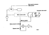
- a typical conventional hydraulic circuit for the control and operation of a slew motor is depicted in Figure 2 .
- this make-up fluid supply comprises a conduit connected between a return conduit of a main control valve and the conduits which connect the main control valve to the hydraulic motor.
- the make-up fluid pressure supply comprises a parasitic load on the hydraulic circuit which requires the hydraulic pump to be rated and operated for a higher load than would otherwise be required.
- an aspect of the present invention provides a working machine hydraulic circuit, including: a hydraulic motor; a pilot pressure system configured to supply hydraulic fluid at a pilot pressure to one or more components of the working machine; and a make-up pressure system in hydraulic fluid communication with the pilot pressure system and the hydraulic motor, and configured to supply hydraulic fluid to the hydraulic motor from the pilot pressure system if the hydraulic fluid pressure in a part of the hydraulic motor is below a threshold pressure such that, during deceleration of the hydraulic motor, the make-up pressure system is operable to supply fluid from the pilot pressure system to the hydraulic motor to reduce the risk of cavitation in the hydraulic motor.
- the circuit may further include: a hydraulic actuator coupled to the pilot pressure system by a control valve and configured for actuation between a first position and a second position on the supply of hydraulic fluid from the pilot pressure system to the control valve.
- the hydraulic motor may be a slew motor.
- the make-up pressure system may further include a valve configured to restrict or substantially prevent the flow of fluid from the hydraulic motor to the pilot pressure system.
- the make-up pressure system may further include a valve configured to restrict or substantially prevent the flow of fluid from the pilot pressure system to the hydraulic motor when a fluid pressure in the pilot pressure system is less than a threshold fluid pressure.
- the make-up pressure system may further include a valve configured to restrict or substantially prevent the flow of fluid from the hydraulic motor to the pilot pressure system and configured to restrict or substantially prevent the flow of fluid from the pilot pressure system to the hydraulic motor when a fluid pressure in the pilot pressure system is less than a threshold fluid pressure.
- the valve may include a check valve.
- the valve may include a solenoid valve.
- the valve may include a pilot operated valve.
- Another aspect of the invention provides a working machine including a hydraulic circuit.
- the machine may further include a working arm and the pilot pressure system is configured to supply hydraulic fluid to one or more control valves associated with one or more hydraulic actuators of the working machine which are configured to drive the operation of the working arm or a part of the working arm.
- the machine may be an excavator.
- an embodiment of the present invention comprises a hydraulic circuit 1 for slew motor control 2 of a working machine 3 (see figure 1 ).
- the hydraulic circuit 1 is configured to control the operation of a hydraulic motor 13 (a slew motor) which is coupled to the working machine 3 such that operation of the hydraulic motor 13 causes rotation of a main body 31 with respect to an undercarriage 32 of the working machine 3 (a slew operation).
- a hydraulic motor 13 a slew motor
- the hydraulic circuit 1 may be located in the main body 31 of the working machine 3 or in the undercarriage 32 of the working machine 3 or may be partially located in both the main body 31 and the undercarriage 32 of the working machine 3.
- the hydraulic circuit 1 is located in the main body 31 of the machine 3.
- the main body 31 may, in an embodiment, be attached to a working arm 33.
- the working arm 33 is attached at a proximal end thereof to the main body 31 of the working machine 3 and a distal end of the boom 33 is configured to carry a working implement or tool 34 (such as a bucket).
- the working arm 33 may be pivotally connected to the main body 31 such that it can be raised and lowered with respect to the main body 31 and may include one or more pivotal joints.
- the working arm 33 may be pivotally connected to the main body 31 such that it can be rotated between a left and a right position with respect to the main body 31.
- the working arm 33 may comprise a first section 331 (a boom) attached to the main body 31 and a second section 332 (a dipper arm) attached to the first section 331 by a pivotal joint.
- One or more hydraulic rams or other hydraulic actuators may be provided to move the working arm 33 or a part or section thereof with respect to the main body 31.
- the or each hydraulic ram or actuator includes a hydraulic circuit and may include one or more control valves which are operated, at least in part, by a pilot pressure supply which can be actuated by a user operating a user control.
- the pilot pressure supply is provided by a pilot pressure system of the machine 3 and may be used to control the operation of one or more parts of the machine 3.
- each hydraulic ram or actuator is configured for movement between a first and a second position and to drive movement of the working arm 33 (for example) between a first and a second position.
- Other configurations of the working arm 33 are provided in accordance with embodiments of the present invention.
- the main body 31 houses an engine for the machine 3.
- a system pilot pressure (typically around 35 bar (3500 KPa)) is provided by a pressure maintaining valve 4 along a pilot pressure conduit 5.
- This system pilot pressure may be used by other components of the working machine 3 - for example, to control one or more spools of a main control valve to operate a ram coupled to the working arm 33.
- the pilot pressure conduit 5 may, therefore, be connected to or form part of a pilot pressure system of the machine 3.
- the pressure maintaining valve 4 is coupled by a first conduit 6 to an accumulator 7 such that the pressure maintaining valve 4 and accumulator 7 are in fluid communication.
- the pressure maintaining valve 4 is also coupled to a hydraulic pump 8 by a second conduit 9 such that the pressure maintaining valve 4 and hydraulic pump 8 are in fluid communication.
- the hydraulic pump 8 is in fluid communication with a low pressure hydraulic fluid reservoir 10.
- the pressure maintaining valve 4 uses fluid supplied under pressure from the hydraulic pump 8 to provide the system pilot pressure.
- the accumulator 7 is used to ensure that this system pilot pressure is maintained substantially at a predetermined level during operation of the working machine 3.
- the pressure maintaining valve 4 and the accumulator 7 may, therefore, form part of the pilot pressure system of the machine 3.
- a main control valve 11 is coupled to the hydraulic pump 8 by a main control valve supply conduit 12 such that the main control valve 11 and hydraulic pump 8 are in fluid communication.
- the main control valve supply conduit 12 connects, in this example, to the second conduit 9.
- the main control valve 11 is coupled to a hydraulic motor 13 (e.g. a slew motor) by third 14 and fourth 15 conduits such that the main control valve 11 is in fluid communication with the hydraulic motor 13.
- the arrangement is such that to drive a moving part of the hydraulic motor 13 in a first direction, fluid under pressure is supplied to the hydraulic motor 13 from the main control valve 11 through the third conduit 14 and fluid is passed from the hydraulic motor 13 to the main control valve 11 through the fourth conduit 15.
- fluid under pressure is supplied to the hydraulic motor 13 from the main control valve 11 through the fourth conduit 15 and fluid is passed from the hydraulic motor 13 to the main control valve 11 through the third conduit 14.
- main control valve 11 may comprise multiple valves forming a hydraulic control circuit and the operation of the main control valve 11 may be controlled by a user through user controls which may be provide in the main body 31 of the machine 3 (in an operator cab thereof).
- first 16 and second 17 relief valves are provided between the third 14 and fourth 15 conduits and are both connected in parallel with the hydraulic motor 13 in fluid communication therewith.
- the two pressure relief valves 16,17 are arranged in an opposing configuration with respect to each other - the first relief valve 16 being configured to relieve an excessive fluid pressure in the third conduit 14 by allowing fluid to pass to the fourth conduit 15 and the second relief valve 17 being configured to relieve an excessive fluid pressure in the fourth conduit 15 by allowing fluid to pass to the third conduit 14 (the first 16 and second 17 relief valves normally being closed).
- a moving part of the hydraulic motor 13 may have significant momentum when the control valve 11 is operated to prevent substantive quantities of fluid from entering or leaving the third 14 and fourth 15 conduits. Accordingly, depending on the direction of movement (e.g. rotation) of a moving part of the hydraulic motor 13 at that juncture, the fluid pressure in the third 13 or fourth 14 conduit may increase and this fluid pressure may be relieved through the relevant relief valve 16,17. As will be understood, this has the effect of damping the deceleration of a moving part of the hydraulic motor 13.
- the main control valve 11 is coupled to, and is in fluid communication with, a cooler 18 by a fifth conduit 19 which provides a return conduit for the main control valve 11.
- the cooler 18 is configured to cool hydraulic fluid flowing therethrough and is in fluid communication with a filter 20.
- the filter 20 is in fluid communication with a low pressure reservoir 21 of hydraulic fluid which may be the same reservoir 10 as is coupled to the hydraulic pump 8.
- a bypass check valve 22 may be provided and may be connected in parallel with the cooler 18 such that if the fluid pressure in the fifth conduit 19 exceeds the cracking pressure of the bypass check valve 22, the bypass check valve 22 will allow fluid to bypass the cooler 18 such that fluid can pass from the fifth conduit 19 to the filter 20 without passing through the cooler 18.
- the bypass check valve 22 can be used to permit a portion of the fluid in the fifth conduit 19 to bypass the cooler 18 whilst allowing a portion of the fluid in the fifth conduit 19 to pass through the cooler 18.
- the bypass check valve 22 acts to control the fluid pressure of the fluid which passes through the cooler 18.
- a make-up pressure conduit 23 is connected, in an embodiment, by a first make-up pressure check valve 24 to the third conduit 14 and by a second make-up pressure check valve 25 to the fourth conduit 15.
- the first make-up check valve 24 is arranged such that fluid can pass from the make-up pressure conduit 23 to the third conduit 14 but fluid is prevented from flowing in the opposing direction.
- the second make-up check valve 25 is arranged such that fluid can pass from the make-up pressure conduit 23 to the fourth conduit 15 but fluid is prevented from flowing in the opposing direction.
- Fluid is supplied through the make-up pressure conduit 23 at a make-up fluid pressure such that fluid passes through the first make-up check valve 24 to the third conduit 14 if the fluid pressure in the third conduit 14 falls below the make-up fluid pressure, and fluid passes through the second make-up check valve 25 to the fourth conduit 15 if the fluid pressure in the fourth conduit 15 falls below the make-up fluid pressure.
- fluid is supplied to the hydraulic motor if there is a sufficient fluid pressure drop in either the third or the fourth conduit 14,15 with a view to reducing the likelihood of cavitation in the hydraulic motor 13.
- the make-up pressure conduit 23 is connected to the accumulator 7 and is in fluid communication therewith. In an embodiment, the make-up pressure conduit 23 is connected to the pilot pressure conduit 5 and is in fluid communication therewith. In an embodiment, the make-up pressure conduit 23 is connected to another part of a pilot pressure system of the working machine 3 and is in fluid communication therewith. The fluid pressure within the pilot pressure conduit 5 is, in an embodiment, operated in isolation from the fluid pressure in the make-up pressure conduit 23.
- the make-up pressure conduit 23 is connected to the first conduit 6 and is in fluid communication with the first conduit 6.
- the make-up fluid pressure is provided by the accumulator 7, the pressure maintaining valve 4, and the hydraulic pump 8.
- the make-up pressure is, in other words, provided by the pilot pressure system of the working machine 3 and does not form a continuous parasitic load on fluid pressure in the return conduit (the fifth conduit 19) of the main control valve 11. This allows a reduction in the back pressure required for operation of the hydraulic circuit 1.
- a less powerful hydraulic pump 8 may be used and/or the fuel volume required to operate the hydraulic pump 8 for a given period may be lower.
- a make-up pressure valve 26 is provided in the make-up pressure conduit 23.
- the make-up pressure valve 26 may be a check valve.
- the make-up pressure valve 26 is configured to prevent the flow of fluid towards the accumulator 7 and to permit the flow of fluid from the accumulator 7 if the fluid pressure is higher than a predetermined fluid pressure (this may be achieved by selecting a check valve with an appropriate cracking pressure if the make-up pressure valve 26 is a check valve).
- a make-up pressure valve 26 may be provided in the make-up pressure conduit 23 to prevent the flow of fluid towards the pilot pressure system and to permit the flow of fluid from the pilot pressure system if the fluid pressure is above a predetermined fluid pressure.
- the make-up pressure check valve 26 provides a mechanism by which the balance can be defined between the use of the pilot fluid pressure in the pilot pressure system of the working machine 3 and the use of the pilot pressure as a source of make-up fluid pressure to reduce the risk of cavitation in the hydraulic motor.
- the cracking pressure of the make-up pressure check valve 26, therefore, may be selected in accordance with the operating characteristics of the pilot pressure system of the machine 3.
- the make-up pressure check valve 26 also helps to reduce the risk of fluid passing from the hydraulic motor 8 back into the pilot pressure system of the working machine 3 in the event of failure of the first 24 or second 25 make-up pressure valves. Such a malfunction could otherwise damage components of the pilot pressure system.
- the make-up pressure check valve 26 also acts to reduce the risk of fluid from the pilot pressure system of the working machine 3 from being exhausted if a slew operation is performed while the hydraulic pump 8 is not operating (perhaps because the working machine 3 engine is turned off). This allows operations such as an emergency lowering of the working arm 33 to take place in such circumstances (as there will still be sufficient pilot clued pressure in the pilot pressure system to allow for control of the working arm 33). This may, for example, be requirement of safety legislation in some territories.
- make-up pressure valve 26 being a check valve
- a make-up pressure pilot valve or solenoid valve may be provided and configured for actuation such that a similar result is achieved.
- the make-up pressure valve 26 may comprise a combination of valves.
- the make-up pressure conduit 23 and the first and second make-up pressure check valves 24,25 for a make-up pressure system are just one example of an arrangement which allows fluid from the make-up pressure conduit to be supplied to the part of the hydraulic motor 13 in which it is required to reduce the risk of cavitation in the hydraulic motor 13.
- the make-up pressure check valves 24,25 are housed in a main body of the hydraulic motor 13.
- the working machine 3 is preferably an excavator machine but it will be appreciated that embodiments of the present invention may be used in relation to other types of working machine 3 which are capable of a slew operation or, indeed, in relation to other working machines 3 which have hydraulic motors for other operations - such operations may include operations in which load holding of a spool of the main control valve 11 is required.
- the working machine 3 may have an undercarriage 32 which includes one or more wheels and/or one or more endless tracks.
- references made herein to the prevention of an act include the absolute prevention of that act or the substantial prevention of that act.
- references made herein to the permitting or allowing of an act include the absolute unrestricted allowing or permitting of that act or the substantial allowing or permitting of that act.
Landscapes
- Engineering & Computer Science (AREA)
- General Engineering & Computer Science (AREA)
- Physics & Mathematics (AREA)
- Fluid Mechanics (AREA)
- Mechanical Engineering (AREA)
- Chemical & Material Sciences (AREA)
- Analytical Chemistry (AREA)
- Mining & Mineral Resources (AREA)
- Civil Engineering (AREA)
- Structural Engineering (AREA)
- Fluid-Pressure Circuits (AREA)
- Operation Control Of Excavators (AREA)
Applications Claiming Priority (1)
| Application Number | Priority Date | Filing Date | Title |
|---|---|---|---|
| GB1106687.5A GB2490320A (en) | 2011-04-20 | 2011-04-20 | Hydraulic circuit with back-up pressure system to prevent cavitation |
Publications (3)
| Publication Number | Publication Date |
|---|---|
| EP2514978A2 true EP2514978A2 (fr) | 2012-10-24 |
| EP2514978A3 EP2514978A3 (fr) | 2014-03-19 |
| EP2514978B1 EP2514978B1 (fr) | 2016-08-24 |
Family
ID=44147292
Family Applications (1)
| Application Number | Title | Priority Date | Filing Date |
|---|---|---|---|
| EP12164245.8A Active EP2514978B1 (fr) | 2011-04-20 | 2012-04-16 | Circuit hydraulique et machine de travail comprenant un tel circuit |
Country Status (6)
| Country | Link |
|---|---|
| US (1) | US20130028695A1 (fr) |
| EP (1) | EP2514978B1 (fr) |
| JP (1) | JP2012229802A (fr) |
| KR (1) | KR101557426B1 (fr) |
| CN (1) | CN102758805B (fr) |
| GB (1) | GB2490320A (fr) |
Cited By (2)
| Publication number | Priority date | Publication date | Assignee | Title |
|---|---|---|---|---|
| DE102014206891A1 (de) | 2014-04-10 | 2015-10-15 | Robert Bosch Gmbh | Hydrostatischer Antrieb |
| DE102015204333A1 (de) | 2014-12-08 | 2016-06-09 | Robert Bosch Gmbh | Druckmitteleinspeisung für einen hydrostatischen Antrieb |
Families Citing this family (11)
| Publication number | Priority date | Publication date | Assignee | Title |
|---|---|---|---|---|
| JP6177562B2 (ja) * | 2013-03-28 | 2017-08-09 | 三菱日立パワーシステムズ株式会社 | 油圧装置及び原動装置 |
| CN103174704B (zh) * | 2013-03-29 | 2016-02-17 | 中联重科股份有限公司渭南分公司 | 液压油过滤系统和液压挖掘机 |
| US20160142122A1 (en) * | 2013-10-17 | 2016-05-19 | Qualcomm Incorporated | Methods and apparatus for channel state information feedback |
| KR102128630B1 (ko) * | 2014-03-24 | 2020-06-30 | 두산인프라코어 주식회사 | 유압시스템에서 스윙 모터의 제어방법 및 유압시스템 |
| JP6522386B2 (ja) * | 2015-03-26 | 2019-05-29 | 住友重機械工業株式会社 | ショベル |
| CN106638739B (zh) * | 2017-02-10 | 2019-02-19 | 柳州柳工挖掘机有限公司 | 具有平地辅助电控系统的挖掘机 |
| JP6999320B2 (ja) * | 2017-07-26 | 2022-01-18 | 住友建機株式会社 | ショベル |
| US20210301842A1 (en) * | 2020-03-31 | 2021-09-30 | Deere & Company | Drain for hydraulic system |
| KR102893088B1 (ko) * | 2022-06-02 | 2025-12-03 | 레디로버스트머신 주식회사 | 건설기계용 기생부하 저감형 에너지 변환 시스템 |
| WO2023234643A1 (fr) * | 2022-06-02 | 2023-12-07 | 레디로버스트머신 주식회사 | Système de conversion d'énergie de réduction de charge parasite pour engin de chantier |
| JP2023183040A (ja) * | 2022-06-15 | 2023-12-27 | キャタピラー エス エー アール エル | 建設機械の油圧回路 |
Family Cites Families (16)
| Publication number | Priority date | Publication date | Assignee | Title |
|---|---|---|---|---|
| JPS5847283Y2 (ja) * | 1980-01-18 | 1983-10-28 | 日立建機株式会社 | 油圧駆動作業機のモ−タ回路 |
| JPS57129990U (fr) * | 1981-02-09 | 1982-08-13 | ||
| JPS60260704A (ja) * | 1984-06-08 | 1985-12-23 | Toshiba Mach Co Ltd | 油圧制御装置 |
| JPH0621971Y2 (ja) * | 1987-03-27 | 1994-06-08 | 油谷重工株式会社 | 油圧シヨベルの油圧回路 |
| JPH0165902U (fr) * | 1987-10-21 | 1989-04-27 | ||
| JP2690353B2 (ja) * | 1989-03-30 | 1997-12-10 | 日立建機株式会社 | ロードセンシングシステムを用いた油圧回路のメイクアップ装置 |
| JP2724888B2 (ja) * | 1989-09-28 | 1998-03-09 | 日立建機株式会社 | 可変容量型油圧モータの制御回路 |
| JP3692004B2 (ja) * | 2000-03-16 | 2005-09-07 | 新キャタピラー三菱株式会社 | 流体圧回路装置 |
| US6619183B2 (en) * | 2001-12-07 | 2003-09-16 | Caterpillar Inc | Electrohydraulic valve assembly |
| JP2003287001A (ja) * | 2002-03-28 | 2003-10-10 | Kubota Corp | 油圧モータ操作回路 |
| JP2003294006A (ja) * | 2002-03-29 | 2003-10-15 | Shin Caterpillar Mitsubishi Ltd | 油圧式作業機械の旋回メイクアップ回路 |
| JP2004324838A (ja) * | 2003-04-28 | 2004-11-18 | Shin Caterpillar Mitsubishi Ltd | 建設機械における油圧回路 |
| JP4151597B2 (ja) * | 2004-03-31 | 2008-09-17 | コベルコ建機株式会社 | 油圧制御回路および建設機械 |
| US7640735B2 (en) * | 2005-09-19 | 2010-01-05 | Parker-Hannifin Corporation | Auxiliary pump for hydrostatic transmission |
| JP5257807B2 (ja) * | 2006-11-14 | 2013-08-07 | フスコ インターナショナル インコーポレイテッド | 油圧システムのためのエネルギー回収及び再利用技術 |
| CN101798830B (zh) * | 2010-02-25 | 2011-11-09 | 三一重机有限公司 | 一种液压挖掘机背压控制方法 |
-
2011
- 2011-04-20 GB GB1106687.5A patent/GB2490320A/en not_active Withdrawn
-
2012
- 2012-04-16 EP EP12164245.8A patent/EP2514978B1/fr active Active
- 2012-04-18 JP JP2012094775A patent/JP2012229802A/ja active Pending
- 2012-04-19 US US13/450,673 patent/US20130028695A1/en not_active Abandoned
- 2012-04-19 KR KR1020120041067A patent/KR101557426B1/ko active Active
- 2012-04-20 CN CN201210129329.9A patent/CN102758805B/zh active Active
Non-Patent Citations (1)
| Title |
|---|
| None |
Cited By (2)
| Publication number | Priority date | Publication date | Assignee | Title |
|---|---|---|---|---|
| DE102014206891A1 (de) | 2014-04-10 | 2015-10-15 | Robert Bosch Gmbh | Hydrostatischer Antrieb |
| DE102015204333A1 (de) | 2014-12-08 | 2016-06-09 | Robert Bosch Gmbh | Druckmitteleinspeisung für einen hydrostatischen Antrieb |
Also Published As
| Publication number | Publication date |
|---|---|
| US20130028695A1 (en) | 2013-01-31 |
| KR20120120056A (ko) | 2012-11-01 |
| EP2514978A3 (fr) | 2014-03-19 |
| JP2012229802A (ja) | 2012-11-22 |
| GB201106687D0 (en) | 2011-06-01 |
| CN102758805A (zh) | 2012-10-31 |
| CN102758805B (zh) | 2015-09-16 |
| GB2490320A (en) | 2012-10-31 |
| EP2514978B1 (fr) | 2016-08-24 |
| KR101557426B1 (ko) | 2015-10-06 |
Similar Documents
| Publication | Publication Date | Title |
|---|---|---|
| EP2514978B1 (fr) | Circuit hydraulique et machine de travail comprenant un tel circuit | |
| CN104583611B (zh) | 具有超压保护的液压控制系统 | |
| CN103890412B (zh) | 液压控制装置及具备该液压控制装置的工程机械 | |
| CN103459857B (zh) | 作业机械的液压驱动装置 | |
| KR102403991B1 (ko) | 건설기계의 붐 증속 유압 시스템 | |
| EP3106677B1 (fr) | Appareil motrice hydraulique pour machine de construction | |
| US10604915B2 (en) | Hydraulic system and hydraulic control method for construction machine | |
| KR102082028B1 (ko) | 붐 에너지 회생 제어 회로 및 제어 방법 | |
| WO2012107186A1 (fr) | Système hydrostatique configuré pour être intégré dans une excavatrice | |
| CN113195904B (zh) | 工程机械中的液压缸的驱动装置 | |
| JP2024025818A (ja) | ショベル | |
| US20140283915A1 (en) | Hydraulic Control System Having Relief Flow Capture | |
| JP4879551B2 (ja) | 作業機械のブームエネルギの回生装置及びエネルギの回生装置 | |
| JP4937176B2 (ja) | 作業機械 | |
| JP6292970B2 (ja) | 圧力制御弁および作業機械 | |
| JP5420470B2 (ja) | 作業機のカウンタウエイト着脱用油圧回路 | |
| CN117242268A (zh) | 用于液压系统返回回路的冷却器旁路阀组件 | |
| JP2018044366A (ja) | 作業機械の挟み処理装置及びこれを備えた作業機械 | |
| JP5498325B2 (ja) | 作業機械の油圧制御回路 | |
| JP2015145602A (ja) | 油圧ユニット | |
| KR20130087775A (ko) | 건설기계의 캐빈의 도어 개폐장치 | |
| JP6949783B2 (ja) | 作業機の油圧システム | |
| CN118728780A (zh) | 控制阀以及建筑机械 | |
| JP2009293689A (ja) | 油圧走行車のフリー走行装置 | |
| JP6541457B2 (ja) | 油圧式作業機 |
Legal Events
| Date | Code | Title | Description |
|---|---|---|---|
| PUAI | Public reference made under article 153(3) epc to a published international application that has entered the european phase |
Free format text: ORIGINAL CODE: 0009012 |
|
| AK | Designated contracting states |
Kind code of ref document: A2 Designated state(s): AL AT BE BG CH CY CZ DE DK EE ES FI FR GB GR HR HU IE IS IT LI LT LU LV MC MK MT NL NO PL PT RO RS SE SI SK SM TR |
|
| AX | Request for extension of the european patent |
Extension state: BA ME |
|
| PUAL | Search report despatched |
Free format text: ORIGINAL CODE: 0009013 |
|
| AK | Designated contracting states |
Kind code of ref document: A3 Designated state(s): AL AT BE BG CH CY CZ DE DK EE ES FI FR GB GR HR HU IE IS IT LI LT LU LV MC MK MT NL NO PL PT RO RS SE SI SK SM TR |
|
| AX | Request for extension of the european patent |
Extension state: BA ME |
|
| RIC1 | Information provided on ipc code assigned before grant |
Ipc: F15B 21/04 20060101AFI20140210BHEP |
|
| 17P | Request for examination filed |
Effective date: 20140804 |
|
| RBV | Designated contracting states (corrected) |
Designated state(s): AL AT BE BG CH CY CZ DE DK EE ES FI FR GB GR HR HU IE IS IT LI LT LU LV MC MK MT NL NO PL PT RO RS SE SI SK SM TR |
|
| 17Q | First examination report despatched |
Effective date: 20150120 |
|
| REG | Reference to a national code |
Ref country code: DE Ref legal event code: R079 Ref document number: 602012022105 Country of ref document: DE Free format text: PREVIOUS MAIN CLASS: F15B0021040000 Ipc: F15B0021000000 |
|
| GRAP | Despatch of communication of intention to grant a patent |
Free format text: ORIGINAL CODE: EPIDOSNIGR1 |
|
| RIC1 | Information provided on ipc code assigned before grant |
Ipc: F15B 21/00 20060101AFI20160113BHEP |
|
| INTG | Intention to grant announced |
Effective date: 20160202 |
|
| GRAP | Despatch of communication of intention to grant a patent |
Free format text: ORIGINAL CODE: EPIDOSNIGR1 |
|
| INTG | Intention to grant announced |
Effective date: 20160315 |
|
| GRAS | Grant fee paid |
Free format text: ORIGINAL CODE: EPIDOSNIGR3 |
|
| GRAA | (expected) grant |
Free format text: ORIGINAL CODE: 0009210 |
|
| AK | Designated contracting states |
Kind code of ref document: B1 Designated state(s): AL AT BE BG CH CY CZ DE DK EE ES FI FR GB GR HR HU IE IS IT LI LT LU LV MC MK MT NL NO PL PT RO RS SE SI SK SM TR |
|
| REG | Reference to a national code |
Ref country code: GB Ref legal event code: FG4D |
|
| REG | Reference to a national code |
Ref country code: CH Ref legal event code: EP |
|
| REG | Reference to a national code |
Ref country code: AT Ref legal event code: REF Ref document number: 823379 Country of ref document: AT Kind code of ref document: T Effective date: 20160915 |
|
| REG | Reference to a national code |
Ref country code: IE Ref legal event code: FG4D |
|
| REG | Reference to a national code |
Ref country code: DE Ref legal event code: R096 Ref document number: 602012022105 Country of ref document: DE |
|
| REG | Reference to a national code |
Ref country code: SE Ref legal event code: TRGR |
|
| REG | Reference to a national code |
Ref country code: LT Ref legal event code: MG4D |
|
| REG | Reference to a national code |
Ref country code: NL Ref legal event code: MP Effective date: 20160824 |
|
| REG | Reference to a national code |
Ref country code: AT Ref legal event code: MK05 Ref document number: 823379 Country of ref document: AT Kind code of ref document: T Effective date: 20160824 |
|
| PG25 | Lapsed in a contracting state [announced via postgrant information from national office to epo] |
Ref country code: LT Free format text: LAPSE BECAUSE OF FAILURE TO SUBMIT A TRANSLATION OF THE DESCRIPTION OR TO PAY THE FEE WITHIN THE PRESCRIBED TIME-LIMIT Effective date: 20160824 Ref country code: NL Free format text: LAPSE BECAUSE OF FAILURE TO SUBMIT A TRANSLATION OF THE DESCRIPTION OR TO PAY THE FEE WITHIN THE PRESCRIBED TIME-LIMIT Effective date: 20160824 Ref country code: RS Free format text: LAPSE BECAUSE OF FAILURE TO SUBMIT A TRANSLATION OF THE DESCRIPTION OR TO PAY THE FEE WITHIN THE PRESCRIBED TIME-LIMIT Effective date: 20160824 Ref country code: FI Free format text: LAPSE BECAUSE OF FAILURE TO SUBMIT A TRANSLATION OF THE DESCRIPTION OR TO PAY THE FEE WITHIN THE PRESCRIBED TIME-LIMIT Effective date: 20160824 Ref country code: NO Free format text: LAPSE BECAUSE OF FAILURE TO SUBMIT A TRANSLATION OF THE DESCRIPTION OR TO PAY THE FEE WITHIN THE PRESCRIBED TIME-LIMIT Effective date: 20161124 Ref country code: HR Free format text: LAPSE BECAUSE OF FAILURE TO SUBMIT A TRANSLATION OF THE DESCRIPTION OR TO PAY THE FEE WITHIN THE PRESCRIBED TIME-LIMIT Effective date: 20160824 |
|
| PG25 | Lapsed in a contracting state [announced via postgrant information from national office to epo] |
Ref country code: LV Free format text: LAPSE BECAUSE OF FAILURE TO SUBMIT A TRANSLATION OF THE DESCRIPTION OR TO PAY THE FEE WITHIN THE PRESCRIBED TIME-LIMIT Effective date: 20160824 Ref country code: AT Free format text: LAPSE BECAUSE OF FAILURE TO SUBMIT A TRANSLATION OF THE DESCRIPTION OR TO PAY THE FEE WITHIN THE PRESCRIBED TIME-LIMIT Effective date: 20160824 Ref country code: GR Free format text: LAPSE BECAUSE OF FAILURE TO SUBMIT A TRANSLATION OF THE DESCRIPTION OR TO PAY THE FEE WITHIN THE PRESCRIBED TIME-LIMIT Effective date: 20161125 Ref country code: PT Free format text: LAPSE BECAUSE OF FAILURE TO SUBMIT A TRANSLATION OF THE DESCRIPTION OR TO PAY THE FEE WITHIN THE PRESCRIBED TIME-LIMIT Effective date: 20161226 Ref country code: ES Free format text: LAPSE BECAUSE OF FAILURE TO SUBMIT A TRANSLATION OF THE DESCRIPTION OR TO PAY THE FEE WITHIN THE PRESCRIBED TIME-LIMIT Effective date: 20160824 |
|
| REG | Reference to a national code |
Ref country code: FR Ref legal event code: PLFP Year of fee payment: 6 |
|
| PG25 | Lapsed in a contracting state [announced via postgrant information from national office to epo] |
Ref country code: EE Free format text: LAPSE BECAUSE OF FAILURE TO SUBMIT A TRANSLATION OF THE DESCRIPTION OR TO PAY THE FEE WITHIN THE PRESCRIBED TIME-LIMIT Effective date: 20160824 Ref country code: RO Free format text: LAPSE BECAUSE OF FAILURE TO SUBMIT A TRANSLATION OF THE DESCRIPTION OR TO PAY THE FEE WITHIN THE PRESCRIBED TIME-LIMIT Effective date: 20160824 |
|
| REG | Reference to a national code |
Ref country code: DE Ref legal event code: R097 Ref document number: 602012022105 Country of ref document: DE |
|
| PG25 | Lapsed in a contracting state [announced via postgrant information from national office to epo] |
Ref country code: BE Free format text: LAPSE BECAUSE OF FAILURE TO SUBMIT A TRANSLATION OF THE DESCRIPTION OR TO PAY THE FEE WITHIN THE PRESCRIBED TIME-LIMIT Effective date: 20160824 Ref country code: CZ Free format text: LAPSE BECAUSE OF FAILURE TO SUBMIT A TRANSLATION OF THE DESCRIPTION OR TO PAY THE FEE WITHIN THE PRESCRIBED TIME-LIMIT Effective date: 20160824 Ref country code: SK Free format text: LAPSE BECAUSE OF FAILURE TO SUBMIT A TRANSLATION OF THE DESCRIPTION OR TO PAY THE FEE WITHIN THE PRESCRIBED TIME-LIMIT Effective date: 20160824 Ref country code: BG Free format text: LAPSE BECAUSE OF FAILURE TO SUBMIT A TRANSLATION OF THE DESCRIPTION OR TO PAY THE FEE WITHIN THE PRESCRIBED TIME-LIMIT Effective date: 20161124 Ref country code: DK Free format text: LAPSE BECAUSE OF FAILURE TO SUBMIT A TRANSLATION OF THE DESCRIPTION OR TO PAY THE FEE WITHIN THE PRESCRIBED TIME-LIMIT Effective date: 20160824 Ref country code: SM Free format text: LAPSE BECAUSE OF FAILURE TO SUBMIT A TRANSLATION OF THE DESCRIPTION OR TO PAY THE FEE WITHIN THE PRESCRIBED TIME-LIMIT Effective date: 20160824 Ref country code: PL Free format text: LAPSE BECAUSE OF FAILURE TO SUBMIT A TRANSLATION OF THE DESCRIPTION OR TO PAY THE FEE WITHIN THE PRESCRIBED TIME-LIMIT Effective date: 20160824 |
|
| PLBE | No opposition filed within time limit |
Free format text: ORIGINAL CODE: 0009261 |
|
| STAA | Information on the status of an ep patent application or granted ep patent |
Free format text: STATUS: NO OPPOSITION FILED WITHIN TIME LIMIT |
|
| 26N | No opposition filed |
Effective date: 20170526 |
|
| PG25 | Lapsed in a contracting state [announced via postgrant information from national office to epo] |
Ref country code: SI Free format text: LAPSE BECAUSE OF FAILURE TO SUBMIT A TRANSLATION OF THE DESCRIPTION OR TO PAY THE FEE WITHIN THE PRESCRIBED TIME-LIMIT Effective date: 20160824 |
|
| REG | Reference to a national code |
Ref country code: CH Ref legal event code: PL |
|
| REG | Reference to a national code |
Ref country code: IE Ref legal event code: MM4A |
|
| PG25 | Lapsed in a contracting state [announced via postgrant information from national office to epo] |
Ref country code: MC Free format text: LAPSE BECAUSE OF FAILURE TO SUBMIT A TRANSLATION OF THE DESCRIPTION OR TO PAY THE FEE WITHIN THE PRESCRIBED TIME-LIMIT Effective date: 20160824 |
|
| PG25 | Lapsed in a contracting state [announced via postgrant information from national office to epo] |
Ref country code: LU Free format text: LAPSE BECAUSE OF NON-PAYMENT OF DUE FEES Effective date: 20170416 Ref country code: LI Free format text: LAPSE BECAUSE OF NON-PAYMENT OF DUE FEES Effective date: 20170430 Ref country code: CH Free format text: LAPSE BECAUSE OF NON-PAYMENT OF DUE FEES Effective date: 20170430 |
|
| REG | Reference to a national code |
Ref country code: FR Ref legal event code: PLFP Year of fee payment: 7 |
|
| PG25 | Lapsed in a contracting state [announced via postgrant information from national office to epo] |
Ref country code: IE Free format text: LAPSE BECAUSE OF NON-PAYMENT OF DUE FEES Effective date: 20170416 |
|
| PG25 | Lapsed in a contracting state [announced via postgrant information from national office to epo] |
Ref country code: MT Free format text: LAPSE BECAUSE OF NON-PAYMENT OF DUE FEES Effective date: 20170416 |
|
| PG25 | Lapsed in a contracting state [announced via postgrant information from national office to epo] |
Ref country code: AL Free format text: LAPSE BECAUSE OF FAILURE TO SUBMIT A TRANSLATION OF THE DESCRIPTION OR TO PAY THE FEE WITHIN THE PRESCRIBED TIME-LIMIT Effective date: 20160824 |
|
| PG25 | Lapsed in a contracting state [announced via postgrant information from national office to epo] |
Ref country code: HU Free format text: LAPSE BECAUSE OF FAILURE TO SUBMIT A TRANSLATION OF THE DESCRIPTION OR TO PAY THE FEE WITHIN THE PRESCRIBED TIME-LIMIT; INVALID AB INITIO Effective date: 20120416 |
|
| PG25 | Lapsed in a contracting state [announced via postgrant information from national office to epo] |
Ref country code: CY Free format text: LAPSE BECAUSE OF NON-PAYMENT OF DUE FEES Effective date: 20160824 |
|
| PG25 | Lapsed in a contracting state [announced via postgrant information from national office to epo] |
Ref country code: MK Free format text: LAPSE BECAUSE OF FAILURE TO SUBMIT A TRANSLATION OF THE DESCRIPTION OR TO PAY THE FEE WITHIN THE PRESCRIBED TIME-LIMIT Effective date: 20160824 |
|
| PG25 | Lapsed in a contracting state [announced via postgrant information from national office to epo] |
Ref country code: TR Free format text: LAPSE BECAUSE OF FAILURE TO SUBMIT A TRANSLATION OF THE DESCRIPTION OR TO PAY THE FEE WITHIN THE PRESCRIBED TIME-LIMIT Effective date: 20160824 |
|
| PG25 | Lapsed in a contracting state [announced via postgrant information from national office to epo] |
Ref country code: IS Free format text: LAPSE BECAUSE OF FAILURE TO SUBMIT A TRANSLATION OF THE DESCRIPTION OR TO PAY THE FEE WITHIN THE PRESCRIBED TIME-LIMIT Effective date: 20161224 |
|
| P01 | Opt-out of the competence of the unified patent court (upc) registered |
Effective date: 20230524 |
|
| PGFP | Annual fee paid to national office [announced via postgrant information from national office to epo] |
Ref country code: DE Payment date: 20250422 Year of fee payment: 14 |
|
| PGFP | Annual fee paid to national office [announced via postgrant information from national office to epo] |
Ref country code: IT Payment date: 20250422 Year of fee payment: 14 |
|
| PGFP | Annual fee paid to national office [announced via postgrant information from national office to epo] |
Ref country code: FR Payment date: 20250425 Year of fee payment: 14 |
|
| PGFP | Annual fee paid to national office [announced via postgrant information from national office to epo] |
Ref country code: SE Payment date: 20250429 Year of fee payment: 14 |
|
| PGFP | Annual fee paid to national office [announced via postgrant information from national office to epo] |
Ref country code: GB Payment date: 20260323 Year of fee payment: 15 |