EP2515021A2 - Agencement de filtre de réduction de pression doté d'une protection anti-fuites - Google Patents
Agencement de filtre de réduction de pression doté d'une protection anti-fuites Download PDFInfo
- Publication number
- EP2515021A2 EP2515021A2 EP12154155A EP12154155A EP2515021A2 EP 2515021 A2 EP2515021 A2 EP 2515021A2 EP 12154155 A EP12154155 A EP 12154155A EP 12154155 A EP12154155 A EP 12154155A EP 2515021 A2 EP2515021 A2 EP 2515021A2
- Authority
- EP
- European Patent Office
- Prior art keywords
- annular groove
- housing
- component
- components
- locking element
- Prior art date
- Legal status (The legal status is an assumption and is not a legal conclusion. Google has not performed a legal analysis and makes no representation as to the accuracy of the status listed.)
- Withdrawn
Links
- 239000003638 chemical reducing agent Substances 0.000 title claims description 8
- XLYOFNOQVPJJNP-UHFFFAOYSA-N water Substances O XLYOFNOQVPJJNP-UHFFFAOYSA-N 0.000 claims description 8
- 239000003651 drinking water Substances 0.000 claims description 5
- 235000020188 drinking water Nutrition 0.000 claims description 5
- 238000010438 heat treatment Methods 0.000 claims description 4
- 238000009434 installation Methods 0.000 claims description 4
- 230000037431 insertion Effects 0.000 claims description 3
- 238000003780 insertion Methods 0.000 claims description 3
- 230000002093 peripheral effect Effects 0.000 abstract 1
- 210000002105 tongue Anatomy 0.000 description 8
- 229910001369 Brass Inorganic materials 0.000 description 4
- 239000010951 brass Substances 0.000 description 4
- 150000001875 compounds Chemical class 0.000 description 2
- 230000001419 dependent effect Effects 0.000 description 1
- 239000008236 heating water Substances 0.000 description 1
- 239000000463 material Substances 0.000 description 1
- 230000009993 protective function Effects 0.000 description 1
- 238000007789 sealing Methods 0.000 description 1
Images


Classifications
-
- F—MECHANICAL ENGINEERING; LIGHTING; HEATING; WEAPONS; BLASTING
- F16—ENGINEERING ELEMENTS AND UNITS; GENERAL MEASURES FOR PRODUCING AND MAINTAINING EFFECTIVE FUNCTIONING OF MACHINES OR INSTALLATIONS; THERMAL INSULATION IN GENERAL
- F16L—PIPES; JOINTS OR FITTINGS FOR PIPES; SUPPORTS FOR PIPES, CABLES OR PROTECTIVE TUBING; MEANS FOR THERMAL INSULATION IN GENERAL
- F16L39/00—Joints or fittings for double-walled or multi-channel pipes or pipe assemblies
- F16L39/005—Joints or fittings for double-walled or multi-channel pipes or pipe assemblies for concentric pipes
-
- F—MECHANICAL ENGINEERING; LIGHTING; HEATING; WEAPONS; BLASTING
- F16—ENGINEERING ELEMENTS AND UNITS; GENERAL MEASURES FOR PRODUCING AND MAINTAINING EFFECTIVE FUNCTIONING OF MACHINES OR INSTALLATIONS; THERMAL INSULATION IN GENERAL
- F16L—PIPES; JOINTS OR FITTINGS FOR PIPES; SUPPORTS FOR PIPES, CABLES OR PROTECTIVE TUBING; MEANS FOR THERMAL INSULATION IN GENERAL
- F16L37/00—Couplings of the quick-acting type
- F16L37/08—Couplings of the quick-acting type in which the connection between abutting or axially overlapping ends is maintained by locking members
- F16L37/084—Couplings of the quick-acting type in which the connection between abutting or axially overlapping ends is maintained by locking members combined with automatic locking
- F16L37/086—Couplings of the quick-acting type in which the connection between abutting or axially overlapping ends is maintained by locking members combined with automatic locking by means of latching members pushed radially by spring-like elements
-
- F—MECHANICAL ENGINEERING; LIGHTING; HEATING; WEAPONS; BLASTING
- F16—ENGINEERING ELEMENTS AND UNITS; GENERAL MEASURES FOR PRODUCING AND MAINTAINING EFFECTIVE FUNCTIONING OF MACHINES OR INSTALLATIONS; THERMAL INSULATION IN GENERAL
- F16L—PIPES; JOINTS OR FITTINGS FOR PIPES; SUPPORTS FOR PIPES, CABLES OR PROTECTIVE TUBING; MEANS FOR THERMAL INSULATION IN GENERAL
- F16L37/00—Couplings of the quick-acting type
- F16L37/56—Couplings of the quick-acting type for double-walled or multi-channel pipes or pipe assemblies
- F16L37/565—Concentric pipes
-
- F—MECHANICAL ENGINEERING; LIGHTING; HEATING; WEAPONS; BLASTING
- F16—ENGINEERING ELEMENTS AND UNITS; GENERAL MEASURES FOR PRODUCING AND MAINTAINING EFFECTIVE FUNCTIONING OF MACHINES OR INSTALLATIONS; THERMAL INSULATION IN GENERAL
- F16L—PIPES; JOINTS OR FITTINGS FOR PIPES; SUPPORTS FOR PIPES, CABLES OR PROTECTIVE TUBING; MEANS FOR THERMAL INSULATION IN GENERAL
- F16L2201/00—Special arrangements for pipe couplings
- F16L2201/10—Indicators for correct coupling
Definitions
- the invention relates to a connection arrangement for connecting a first water-conducting component to a second water-conducting component, both of which have a central channel in a housing and an annular channel arranged around the central channel.
- Water-carrying components are, for example, connection fittings for connecting filters, pressure reducers, pressure reducer-filter combinations, water softening devices, water treatment devices and the like.
- connection fitting often takes place via flanges.
- the central channel and the annular channel open into a flat, flat flange at a well-defined location.
- the corresponding counter flange is screwed to the flange by means of screws.
- Known flanges are made of brass. It is fernder known to produce such compounds with a union nut. Again, the union nut and the housing of the components made of brass. Tightening the screws or the union nut requires time and a tool.
- the housing neck no longer open in a flat flange, but are plugged together with the corresponding housing neck. Between the assembled housing stub an annular seal can be provided in a groove.
- connection is freely rotatable about the connection axis. As a result, the installation can also be subsequently adapted to the spatial conditions. There are no tools required.
- the connection is made by simply plugging.
- the locking element engages in the groove of one of the plugged components. As a result, the connection is secured against unintentional release.
- the connection allows the use of plastic components, since no tools are used and no greater forces are exerted on the housing of the components.
- the openings are provided in the outer housing socket with the larger diameter in the region of an outer annular groove on the outer side of the outer housing neck and an elastic ring is provided in the outer annular groove, which generates the bias on the locking element.
- an elastic ring is provided in the outer annular groove, which generates the bias on the locking element.
- a plurality of locking elements are provided.
- four locking elements can be provided which are distributed uniformly over the circumference.
- the elastic ring can be protected against external influences with another ring, which is attached over the elastic ring.
- the latching element and / or the outer housing socket are beveled with the smaller diameter for easier insertion. As a result, the locking element slides over the housing neck and into the annular groove.
- display means are provided, which indicate when the locking element engages in the inner annular groove.
- the indicator means may comprise an inner ring having at least one projection secured to a circumferentially extending, radially movable tongue in the same angular range as the detent element and an outer ring having an aperture in the region of the projection in which the projection is recessed, if Locking element engages in the inner annular groove and over which the projection protrudes outwards when the locking element is not engaged.
- the locking element raises the end of the tongue from below something, as long as it is not engaged in the inner annular groove.
- the tongue is bent slightly outwards.
- the rings also have a protective function against external influences on the elastic ring.
- At least one of the components and / or at least one component from the group consisting of locking element, inner ring and outer ring can be made of plastic. Plastic is much less expensive than brass, which is commonly used in this area.
- One of the components may be a connection fitting for installation in a drinking water pipeline.
- the following components can be connected to the connection fitting: filters, water-hardening devices, pressure reducers, pressure reducer-filter combinations, safety fittings for heating devices.
- the housing of these components can be made of plastic in this type of connection. It is understood that each water treatment device and any safety and / or control valve can be connected to such a connection fitting.
- the compound is also suitable for so-called "sandwich" arrangements, in which several water-bearing components are connected in series.
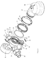
- FIG. 1 shows a generally designated 10 connection fitting.
- the connection fitting 10 is installed in a conventional drinking water pipeline, not shown.
- the present connection fitting 10 is provided with a pressure gauge 16 and a pressure reducer 18. These are provided in the present embodiment, depending on the application for the invention but not mandatory. It is also possible to use simpler connection fittings or connection fittings with other components, such as are common in fittings in the heating and drinking water sector.
- connection fitting 10 To the connection fitting 10, a conventional filter 12 is connected.
- the connection region 14 between the connection fitting 10 and the filter 12 is in FIG. 1 shown in section.
- FIG. 2 shows the connection region 14 and its components in an exploded view.
- connection fitting 10 is made of brass and is installed with an inlet 20 and an outlet 22 in a conventional manner in a pipeline.
- Input 20 and output 22 are formed by nozzles, which are integrally formed on a housing 24.
- the input 20 opens into a central channel 26.
- To the central channel 26 around is a Ring channel 28 formed.
- the annular channel 28 is connected in known manner to the output 22.
- the central channel 26 is formed by an inner housing socket 30.
- the annular channel 28 is formed by an outer housing socket 32 which is arranged coaxially around the inner housing socket 30.
- an outer housing socket 32 In the outer housing socket 32, a continuous outer annular groove 34 is provided outside.
- Four circumferentially extending, elongated apertures 36 are uniformly distributed over the circumference provided in the outer annular groove 34.
- each of the openings 36 locking elements 38 are inserted.
- the locking elements 38 have an edge 40 which rests on the bottom of the outer annular groove 34. This one is good in FIG. 5 to recognize. As a result, the latching element 38 can not slip inwardly through the associated opening 36.
- an elastic ring 42 is inserted into the outer annular groove 34. With the elastic ring 42, the locking elements 38 are pressed inward and biased.
- the inner ring 44 is in FIG. 6 again shown separately in detail.
- the inner ring has four openings 48. It is understood that a different number of openings 48 may be provided.
- the radial openings 48 are elongate and extend in the circumferential direction.
- Tongues 50 are provided in the region of the openings. These are in FIG. 5 clearly visible.
- At the free end of the tongues 50 each cuboid projections 52 are arranged. It is understood that a different shape than cuboid may be provided.
- the other end of the tongue is formed on the bridges 48 located between the openings 48. It is understood that the tongue can also be attached in other ways. In this arrangement, the rectangular projections 52 are slightly radially movable.
- the outer ring 46 On the inner ring 44 of the outer ring 46 is pushed.
- the outer ring 46 has openings 56 in the area of the cuboid projections 52. Otherwise, the outer ring 46 on the inner ring 44. Only the tongues 50 are made somewhat thinner, so that they are movable in the radial direction by a slight distance.
- the housing 58 of the filter 12 has corresponding housing stubs 60 and 62. This is especially in FIG. 3 and 4 clearly visible.
- the filter 12 can be connected to the connector 10 in the manner described below.
- the inner nozzle 30 has at its free end a slightly larger inner diameter. As a result, an annular shoulder 64 is formed.
- the corresponding inner port 60 of the filter has an outer diameter which is adapted to this enlarged inner diameter.
- the inner socket 60 can therefore be inserted to the annular shoulder 64 in the inner socket 30 of the connection fitting 10.
- the inner socket 30 of the connection fitting 10 has on the inside an annular groove into which a seal 66 is inserted. As a result, the inner port 60 of the filter is sealed against the inner port 30 of the connection fitting 10. Both inner sockets 30, 60 have the same inner diameter in the remaining area, so that a continuous central channel 26 is formed.
- the outer nozzle 32 of the connection fitting 10 has at its free end a slightly larger in two stages inside diameter. As a result, two annular shoulders 68 and 70 are formed.
- the outer nozzle 62 of the filter has an external shape adapted to this shape. In the inner region of the nozzle 32 with an enlarged diameter, an annular groove is provided. In the annular groove, a sealing ring 72 is arranged. As a result, the outer neck 62 of the filter is sealed off from the outer neck 32 of the connection fitting 10. Both outer ports 32, 62 have the same inner diameter in the remaining area, so that a continuous annular channel 28 is formed.
- the outer annular groove 34 is provided with the locking elements 38 and the elastic ring 42.
- the nozzle 62 of the filter has an inner annular groove 74, which is arranged in the connected state immediately below the outer annular groove 34. This annular groove 74 is in FIG. 4 clearly visible.
- the inner and outer housing stubs 60 and 62 are inserted into the free end of the inner and outer housing stubs 30 and 32.
- the latching element 38 is pressed against the bias of the elastic ring 42 as far as out until the locking element 38 completely engages in the inner annular groove 74.
- the outer edges 76 of the locking elements 38 and the outer edges 78 of the annular shoulder which is formed by the enlarged diameter of the outer nozzle 62 of the filter, bevelled.
- FIG. 4 shows the situation in which the locking elements 38 are not yet engaged in the annular groove 74. It can be seen that the locking elements 38 are displaced slightly radially outwards.
- FIG. 3 and 5 show the situation in which the locking elements 38 are engaged in the annular groove 74. It can be seen that the locking elements 38 are pressed by the elastic ring radially inwardly into the annular groove 74.
- the projections 52 are arranged. If the locking element 38 is slightly displaced outwards, the overlying projection 52 is also displaced slightly outwards through the apertures 56 in the outer ring 46. As a result, the respective projection 56 protrudes beyond the outer diameter of the outer ring 46. In this way, it can be easily recognized whether all locking elements 38 are engaged and the connection was made in a secure manner or not.
- the use of a plurality of locking elements 38 also allows the indication of whether the connection is sufficiently made at all points.
- each water-bearing component can be connected to another water-bearing component in this way.
- the invention is not limited to the embodiment described.
- the shape of the openings, the locking elements and the projections can be varied. It can be provided in circular openings about cylindrical locking elements, without departing from the spirit. It is also possible to use the nozzles in such a way that the nozzles of the connection fitting are inserted into nozzles on the filter or a water-bearing component used there.
- the invention makes it possible to freely rotate the connection in the assembled state. It may also be used different and in particular more cost-effective plastic materials, since the installer makes the connection only by plugging and no major forces expending, as is the case with screwed connections.
Landscapes
- Engineering & Computer Science (AREA)
- General Engineering & Computer Science (AREA)
- Mechanical Engineering (AREA)
- Quick-Acting Or Multi-Walled Pipe Joints (AREA)
- Flanged Joints, Insulating Joints, And Other Joints (AREA)
Applications Claiming Priority (1)
| Application Number | Priority Date | Filing Date | Title |
|---|---|---|---|
| DE202011000917U DE202011000917U1 (de) | 2011-04-18 | 2011-04-18 | Druckminderer-Filter Anordnung mit Leckageschutz |
Publications (2)
| Publication Number | Publication Date |
|---|---|
| EP2515021A2 true EP2515021A2 (fr) | 2012-10-24 |
| EP2515021A3 EP2515021A3 (fr) | 2012-12-26 |
Family
ID=45562860
Family Applications (1)
| Application Number | Title | Priority Date | Filing Date |
|---|---|---|---|
| EP12154155A Withdrawn EP2515021A3 (fr) | 2011-04-18 | 2012-02-07 | Agencement de filtre de réduction de pression doté d'une protection anti-fuites |
Country Status (3)
| Country | Link |
|---|---|
| EP (1) | EP2515021A3 (fr) |
| CN (1) | CN102748551A (fr) |
| DE (1) | DE202011000917U1 (fr) |
Cited By (1)
| Publication number | Priority date | Publication date | Assignee | Title |
|---|---|---|---|---|
| FR2998938A1 (fr) * | 2012-12-04 | 2014-06-06 | Peugeot Citroen Automobiles Sa | Dispositif de raccordement rapide d'un tuyau coaxial bi-fluides a un equipement de traitement de fluides |
Families Citing this family (4)
| Publication number | Priority date | Publication date | Assignee | Title |
|---|---|---|---|---|
| EP2927471A1 (fr) * | 2014-04-04 | 2015-10-07 | Caterpillar Motoren GmbH & Co. KG | Élément de ligne d'alimentation en carburant à double paroi et bride de raccordement pour celui-ci |
| DE102015121011B4 (de) * | 2015-12-03 | 2018-05-09 | Grünbeck Wasseraufbereitung GmbH | Wasserbehandlungsvorrichtung |
| CN109395446B (zh) * | 2018-11-26 | 2024-11-29 | 路达(厦门)工业有限公司 | 一种易清洗过滤组件及具有该组件的水龙头 |
| CN111473180B (zh) * | 2020-04-02 | 2024-12-06 | 江阴市高新管件有限公司 | 一种快速连接的自来水管接头 |
Family Cites Families (7)
| Publication number | Priority date | Publication date | Assignee | Title |
|---|---|---|---|---|
| GB460786A (en) * | 1935-09-14 | 1937-02-04 | Nuswift Engineering Co Ltd | An improvement in or relating to quick-release hose couplings |
| GB1196584A (en) * | 1966-07-15 | 1970-07-01 | Plalite Ltd | Couplings and Branches for Fire Hoses |
| DE3203254A1 (de) * | 1982-02-01 | 1983-08-04 | Harry 2303 Schinkel Klein | Vorrichtung fuer einen zulauf- und einen ablaufanschluss an ein umlaufsystem mit ineinanderliegenden anschlussstutzen |
| DE19849362C2 (de) * | 1998-10-27 | 2002-10-02 | Kemper Gebr Gmbh & Co Kg | Rohrsystem für flüssige Medien, insbesondere für in Gebäuden verlegte Warmwasserkreise zur Brauchwasserversorgung |
| DE102005051348B4 (de) * | 2005-10-25 | 2007-10-18 | Hans Sasserath & Co. Kg | Baugruppe zum Zuführen von Wasser zu Heizungsanlagen mit Wassererwärmer |
| DE102005052385B4 (de) * | 2005-10-31 | 2008-07-10 | Hans Sasserath & Co. Kg | Druckminderer |
| DE202009008421U1 (de) * | 2009-06-16 | 2010-10-28 | Hans Sasserath & Co. Kg | Adapterarmatur für Ionentauscher |
-
2011
- 2011-04-18 DE DE202011000917U patent/DE202011000917U1/de not_active Expired - Lifetime
-
2012
- 2012-02-07 EP EP12154155A patent/EP2515021A3/fr not_active Withdrawn
- 2012-04-17 CN CN201210112124XA patent/CN102748551A/zh active Pending
Non-Patent Citations (1)
| Title |
|---|
| None |
Cited By (1)
| Publication number | Priority date | Publication date | Assignee | Title |
|---|---|---|---|---|
| FR2998938A1 (fr) * | 2012-12-04 | 2014-06-06 | Peugeot Citroen Automobiles Sa | Dispositif de raccordement rapide d'un tuyau coaxial bi-fluides a un equipement de traitement de fluides |
Also Published As
| Publication number | Publication date |
|---|---|
| DE202011000917U1 (de) | 2012-07-19 |
| CN102748551A (zh) | 2012-10-24 |
| EP2515021A3 (fr) | 2012-12-26 |
Similar Documents
| Publication | Publication Date | Title |
|---|---|---|
| EP2522894B1 (fr) | Fermeture à baïonnette | |
| EP3361134B1 (fr) | Unité de liaison | |
| EP2724065B1 (fr) | Raccord de tuyau flexible et système de tuyau flexible correspondant | |
| DE202017100423U1 (de) | Schlauchanschlussanordnung, Verwendung einer Schlauchanschlussanordnung und Sanitärarmatur | |
| EP2851596A1 (fr) | Élément de traversée murale pour une conduite de fluide et traversée murale | |
| EP3379129A1 (fr) | Connecteur | |
| EP2515021A2 (fr) | Agencement de filtre de réduction de pression doté d'une protection anti-fuites | |
| EP3244962A1 (fr) | Dispositif de raccordement pour système de ligne de fluide médical | |
| EP3312352A1 (fr) | Élément rapporté doté d'un boîtier de cartouche acheminant de l'eau | |
| DE102010018954B4 (de) | Vorrichtung zum steckbaren Verbinden eines ersten Leitungsabschnitts mit einem zweiten Leitungsabschnitt einer Fluidleitung | |
| DE102011050455A1 (de) | Sensoranordnung mit zwei gegeneinander drehbaren Gehäuseteilen | |
| DE202015104332U1 (de) | Schlauchkupplung | |
| EP3322923B1 (fr) | Raccord de conduite sanitaire | |
| CH667164A5 (de) | Bajonettartige kupplung zum verbinden zweier hohlzylindrischer teile. | |
| EP2843283B1 (fr) | Système de convoyeur par succion | |
| DE102012201699A1 (de) | Anschlusseinrichtung für eine Sanitärarmatur | |
| DE19816322C2 (de) | Wasserzähler-Anschluß und Wasserzähler-Einheit | |
| WO2016075579A1 (fr) | Dispositif de raccordement et table de cuisson à gaz | |
| EP3557108A1 (fr) | Dispositif de raccordement pour conduites de fluide | |
| DE102013211188A1 (de) | Anschlussstück sowie Montagesatz | |
| DE202015101609U1 (de) | Verteilervorrichtung | |
| DE102015008858A1 (de) | Sanitärer Leitungsanschluss | |
| DE102010022490B4 (de) | Druckmessvorrichtung mit einem zweiteilig aufgebauten Anschluss an ein druckführendes Prozesssystem | |
| DE202010000872U1 (de) | Vorrichtung zum Verbinden eines Rohres mit einem Anschlussstutzen eines Armaturenanschlusses oder Fittings | |
| EP0286715B1 (fr) | Raccord à vis |
Legal Events
| Date | Code | Title | Description |
|---|---|---|---|
| PUAI | Public reference made under article 153(3) epc to a published international application that has entered the european phase |
Free format text: ORIGINAL CODE: 0009012 |
|
| AK | Designated contracting states |
Kind code of ref document: A2 Designated state(s): AL AT BE BG CH CY CZ DE DK EE ES FI FR GB GR HR HU IE IS IT LI LT LU LV MC MK MT NL NO PL PT RO RS SE SI SK SM TR |
|
| AX | Request for extension of the european patent |
Extension state: BA ME |
|
| PUAL | Search report despatched |
Free format text: ORIGINAL CODE: 0009013 |
|
| AK | Designated contracting states |
Kind code of ref document: A3 Designated state(s): AL AT BE BG CH CY CZ DE DK EE ES FI FR GB GR HR HU IE IS IT LI LT LU LV MC MK MT NL NO PL PT RO RS SE SI SK SM TR |
|
| AX | Request for extension of the european patent |
Extension state: BA ME |
|
| RIC1 | Information provided on ipc code assigned before grant |
Ipc: F16L 37/56 20060101ALI20121119BHEP Ipc: F16L 39/00 20060101ALI20121119BHEP Ipc: F16L 37/084 20060101AFI20121119BHEP Ipc: F16L 37/086 20060101ALI20121119BHEP |
|
| STAA | Information on the status of an ep patent application or granted ep patent |
Free format text: STATUS: THE APPLICATION IS DEEMED TO BE WITHDRAWN |
|
| 18D | Application deemed to be withdrawn |
Effective date: 20130627 |