EP2515036A2 - Chaudière - Google Patents
Chaudière Download PDFInfo
- Publication number
- EP2515036A2 EP2515036A2 EP12164206A EP12164206A EP2515036A2 EP 2515036 A2 EP2515036 A2 EP 2515036A2 EP 12164206 A EP12164206 A EP 12164206A EP 12164206 A EP12164206 A EP 12164206A EP 2515036 A2 EP2515036 A2 EP 2515036A2
- Authority
- EP
- European Patent Office
- Prior art keywords
- combustion gases
- vortex chamber
- outlet
- combustion
- chamber
- Prior art date
- Legal status (The legal status is an assumption and is not a legal conclusion. Google has not performed a legal analysis and makes no representation as to the accuracy of the status listed.)
- Withdrawn
Links
- 239000000567 combustion gas Substances 0.000 claims abstract description 31
- 238000010438 heat treatment Methods 0.000 claims abstract description 15
- 239000000446 fuel Substances 0.000 claims abstract description 6
- 239000004449 solid propellant Substances 0.000 claims description 8
- 239000007789 gas Substances 0.000 claims description 5
- 238000002485 combustion reaction Methods 0.000 abstract description 21
- 238000002156 mixing Methods 0.000 description 4
- 230000000694 effects Effects 0.000 description 3
- 238000000197 pyrolysis Methods 0.000 description 3
- 238000010304 firing Methods 0.000 description 2
- 239000008188 pellet Substances 0.000 description 2
- 229910001018 Cast iron Inorganic materials 0.000 description 1
- 229910000831 Steel Inorganic materials 0.000 description 1
- 230000015572 biosynthetic process Effects 0.000 description 1
- 230000003247 decreasing effect Effects 0.000 description 1
- 230000001419 dependent effect Effects 0.000 description 1
- 238000011161 development Methods 0.000 description 1
- 230000018109 developmental process Effects 0.000 description 1
- 229930195733 hydrocarbon Natural products 0.000 description 1
- 150000002430 hydrocarbons Chemical class 0.000 description 1
- 238000009434 installation Methods 0.000 description 1
- 230000003647 oxidation Effects 0.000 description 1
- 238000007254 oxidation reaction Methods 0.000 description 1
- 239000010959 steel Substances 0.000 description 1
- 238000003756 stirring Methods 0.000 description 1
Images

Classifications
-
- F—MECHANICAL ENGINEERING; LIGHTING; HEATING; WEAPONS; BLASTING
- F23—COMBUSTION APPARATUS; COMBUSTION PROCESSES
- F23B—METHODS OR APPARATUS FOR COMBUSTION USING ONLY SOLID FUEL
- F23B10/00—Combustion apparatus characterised by the combination of two or more combustion chambers
- F23B10/02—Combustion apparatus characterised by the combination of two or more combustion chambers including separate secondary combustion chambers
-
- F—MECHANICAL ENGINEERING; LIGHTING; HEATING; WEAPONS; BLASTING
- F23—COMBUSTION APPARATUS; COMBUSTION PROCESSES
- F23B—METHODS OR APPARATUS FOR COMBUSTION USING ONLY SOLID FUEL
- F23B5/00—Combustion apparatus with arrangements for burning uncombusted material from primary combustion
- F23B5/04—Combustion apparatus with arrangements for burning uncombusted material from primary combustion in separate combustion chamber; on separate grate
-
- F—MECHANICAL ENGINEERING; LIGHTING; HEATING; WEAPONS; BLASTING
- F23—COMBUSTION APPARATUS; COMBUSTION PROCESSES
- F23B—METHODS OR APPARATUS FOR COMBUSTION USING ONLY SOLID FUEL
- F23B60/00—Combustion apparatus in which the fuel burns essentially without moving
- F23B60/02—Combustion apparatus in which the fuel burns essentially without moving with combustion air supplied through a grate
-
- F—MECHANICAL ENGINEERING; LIGHTING; HEATING; WEAPONS; BLASTING
- F23—COMBUSTION APPARATUS; COMBUSTION PROCESSES
- F23B—METHODS OR APPARATUS FOR COMBUSTION USING ONLY SOLID FUEL
- F23B80/00—Combustion apparatus characterised by means creating a distinct flow path for flue gases or for non-combusted gases given off by the fuel
- F23B80/04—Combustion apparatus characterised by means creating a distinct flow path for flue gases or for non-combusted gases given off by the fuel by means for guiding the flow of flue gases, e.g. baffles
-
- F—MECHANICAL ENGINEERING; LIGHTING; HEATING; WEAPONS; BLASTING
- F23—COMBUSTION APPARATUS; COMBUSTION PROCESSES
- F23C—METHODS OR APPARATUS FOR COMBUSTION USING FLUID FUEL OR SOLID FUEL SUSPENDED IN A CARRIER GAS OR AIR
- F23C3/00—Combustion apparatus characterised by the shape of the combustion chamber
- F23C3/006—Combustion apparatus characterised by the shape of the combustion chamber the chamber being arranged for cyclonic combustion
-
- F—MECHANICAL ENGINEERING; LIGHTING; HEATING; WEAPONS; BLASTING
- F23—COMBUSTION APPARATUS; COMBUSTION PROCESSES
- F23L—SUPPLYING AIR OR NON-COMBUSTIBLE LIQUIDS OR GASES TO COMBUSTION APPARATUS IN GENERAL ; VALVES OR DAMPERS SPECIALLY ADAPTED FOR CONTROLLING AIR SUPPLY OR DRAUGHT IN COMBUSTION APPARATUS; INDUCING DRAUGHT IN COMBUSTION APPARATUS; TOPS FOR CHIMNEYS OR VENTILATING SHAFTS; TERMINALS FOR FLUES
- F23L9/00—Passages or apertures for delivering secondary air for completing combustion of fuel
- F23L9/04—Passages or apertures for delivering secondary air for completing combustion of fuel by discharging the air beyond the fire, i.e. nearer the smoke outlet
-
- F—MECHANICAL ENGINEERING; LIGHTING; HEATING; WEAPONS; BLASTING
- F24—HEATING; RANGES; VENTILATING
- F24B—DOMESTIC STOVES OR RANGES FOR SOLID FUELS; IMPLEMENTS FOR USE IN CONNECTION WITH STOVES OR RANGES
- F24B5/00—Combustion-air or flue-gas circulation in or around stoves or ranges
- F24B5/02—Combustion-air or flue-gas circulation in or around stoves or ranges in or around stoves
- F24B5/021—Combustion-air or flue-gas circulation in or around stoves or ranges in or around stoves combustion-air circulation
- F24B5/025—Supply of secondary air for completing combustion of fuel
Definitions
- the invention relates to a boiler for burning solid fuels, according to the preamble of claim 1.
- Generic boilers essentially consist of a heating medium leading boiler body made of cast iron boiler elements or welded steel sheets. This includes a filling space for fuel with an upper or lateral filling opening and a combustion grate with an ash box arranged therebelow. In this case, a pyrolytic combustion takes place above the combustion grate and thus at the bottom of the fuel quantity in the filling space. Fuel thus continuously slips by the weight from above. In the filling room, the primary air supply takes place.
- Solid fuel boilers for firewood or pellet boilers are known for burning solid fuels.
- the door serves only as a front or top closure and access, and in the second case it receives a corresponding pellet burner.
- Special solid fuel boilers with firing grates and in each case at least one ash box located underneath are widespread.
- Substantially influence on the combustion have the exhaust gas and / or combustion air blowers usually used to supply the combustion with primary air in the area of the pyrolysis zone in the filling space and secondary air in the area of a post-combustion zone.
- a central heating boiler for large-volume firewood is known in which secondary air is supplied from below before a vortex chamber.
- the combustion gases flow through a transfer channel from the filling space tangentially into the vortex chamber, wherein the secondary air enters from a side channel in the transfer channel.
- a vortex chamber is so far very large volume dimensioned because it serves as a secondary combustion chamber to completely oxidize the combustion gas. This requires a sufficient distance within the vortex chamber. At the end of a good temperature uniformity and mixing should be achieved.
- DE 296 05 801 U1 shows a boiler with two vortex chambers in the form of flowed through from bottom to top, vertical, cylindrical combustion shafts.
- a plurality of openings for the entry of secondary air are arranged, and above the floor area, the volatile combustion products flow tangentially from the adjacent hopper into the swirl chamber.
- the invention is therefore based on the object to optimize the quality of combustion of boilers and furnaces for the combustion of solid fuels.
- a boiler according to the invention is characterized in that combustion gases and / or secondary air enter the vortex chamber in the vicinity of an end face in the radial direction from the outside, and in that the vortex chamber has a cross-sectional reduction at the opposite end face in the region of the outlet for the combustion gases.
- the cross-sectional reduction is designed symmetrically to the axis of the swirl chamber, wherein the swirl chamber and the outlet for the combustion gases preferably have a cylindrical cross-section.
- the effectiveness of the measures according to the invention is also given in other, for example, rectangular geometries.
- the diameter of the orifice for the combustion gases is at least 30% smaller than the inner diameter of the vortex chamber.
- the cross-sectional reduction in the region of the outlet for the combustion gases consists of an inwardly projecting collar formed on the vortex chamber.
- the cross-sectional reduction in the region of the outlet for the combustion gases may consist of a diaphragm fixed to the vortex chamber, which has a core hole.
- the aperture in the region of the outlet for the combustion gases may be designed to be adjustable and / or have a plurality of radial guide vanes for swirl generation, in particular in order to influence the downstream combustion gas flow.
- diaphragms can be very well adapted or exchanged as separate parts depending on the performance, so that different firing capacities can be realized with a vortex chamber basic body.
- the invention optimizes the quality of combustion of boilers and solid fuel burning furnaces, as it ensures lower emission levels, especially with regard to unburned hydrocarbons and CO in burning firewood.
- This is achieved essentially by the fact that the combustion gases enter tangentially into the vortex chamber and thereby come into rotation. This is reinforced with the principle according to the invention of the so-called fluid-dynamic stirring within the vortex chamber. Particularly conducive to this effect is the flow constriction according to the invention in the outlet area, which controls the rotation of the Combustion gases amplified. This results in better, more uniform mixing of the combustion gases. Thus, the oxidation is more effective and the combustion is lower emissions.
- the same mixing effect is achieved with approximately half of the available installation space in comparison with vortex chamber concepts from the prior art.
- For the functionally important homogeneous mixing of the gaseous media therefore, according to the invention, for example, only half of the flow path within the vortex chamber is sufficient. And this with the same or longer residence time of the combustion gases in the vortex chamber.
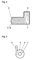
- the boiler consists essentially of a heating medium-carrying boiler body 1, a filling chamber 2 for fuel with an upper filling opening 3, a combustion grate 4 with an ash pan 5 arranged below, a combustion gas outlet opening 6 in a downstream vortex chamber 7 and a subsequent, not shown heat exchanger for the heating gas.
- the vortex chamber 7 consists of a cylindrical space into which combustion gases and / or secondary air enter radially from the outside on one end face. At the opposite end face, the swirl chamber 7 has a cross-sectional reduction in the region of the outlet 8 for the combustion gases, which is designed symmetrically to the axis of the swirl chamber 7 and have a cylindrical cross-section.
Landscapes
- Engineering & Computer Science (AREA)
- Chemical & Material Sciences (AREA)
- Combustion & Propulsion (AREA)
- Mechanical Engineering (AREA)
- General Engineering & Computer Science (AREA)
- Physics & Mathematics (AREA)
- Thermal Sciences (AREA)
- Solid-Fuel Combustion (AREA)
Applications Claiming Priority (1)
| Application Number | Priority Date | Filing Date | Title |
|---|---|---|---|
| DE102011017475A DE102011017475A1 (de) | 2011-04-19 | 2011-04-19 | Heizkessel |
Publications (2)
| Publication Number | Publication Date |
|---|---|
| EP2515036A2 true EP2515036A2 (fr) | 2012-10-24 |
| EP2515036A3 EP2515036A3 (fr) | 2017-10-25 |
Family
ID=45999670
Family Applications (1)
| Application Number | Title | Priority Date | Filing Date |
|---|---|---|---|
| EP12164206.0A Withdrawn EP2515036A3 (fr) | 2011-04-19 | 2012-04-16 | Chaudière |
Country Status (2)
| Country | Link |
|---|---|
| EP (1) | EP2515036A3 (fr) |
| DE (2) | DE102011017475A1 (fr) |
Cited By (2)
| Publication number | Priority date | Publication date | Assignee | Title |
|---|---|---|---|---|
| CN104930517A (zh) * | 2015-06-30 | 2015-09-23 | 中国科学院广州能源研究所 | 一种垃圾热解旋流燃烧装置 |
| ES2791575A1 (es) * | 2020-06-22 | 2020-11-04 | Posada Gonzalez Manuel Enrique | Nuevo quemador de sólidos, de carga y alimentación superior, cámara de combustión y llamas horizontales sin humos, con alto rendimiento |
Families Citing this family (1)
| Publication number | Priority date | Publication date | Assignee | Title |
|---|---|---|---|---|
| DE102013102361B4 (de) * | 2013-03-08 | 2015-01-22 | Ulrich Brunner GmbH | Ofen mit einem Brennraum und einer Brennkammer |
Citations (2)
| Publication number | Priority date | Publication date | Assignee | Title |
|---|---|---|---|---|
| DE19510263A1 (de) | 1994-03-25 | 1995-09-28 | Tiba Ag | Zentralheizungskessel für großvolumiges Stückholz als Brennstoff |
| DE29605801U1 (de) | 1996-03-28 | 1996-06-27 | Georg Fischer GmbH & Co, 89312 Günzburg | Heizkessel |
Family Cites Families (4)
| Publication number | Priority date | Publication date | Assignee | Title |
|---|---|---|---|---|
| DE1081174B (de) * | 1956-05-17 | 1960-05-05 | Olof Axel Ohlsson | Feuerung fuer einen als Heizrohr-Stehkessel ausgebildeten Flammrohr-Rauchrohrkessel |
| GB2089026B (en) * | 1980-12-05 | 1984-03-21 | Coal Industry Patents Ltd | Solid fuel combustion appliances |
| US4638636A (en) * | 1984-06-28 | 1987-01-27 | General Electric Company | Fuel nozzle |
| DE19729506C2 (de) * | 1997-07-10 | 1999-08-05 | Rolf Schnekenburger | Heizkessel zur Feuerung von festen Brennstoffen |
-
2011
- 2011-04-19 DE DE102011017475A patent/DE102011017475A1/de not_active Ceased
- 2011-04-19 DE DE202011110125U patent/DE202011110125U1/de not_active Expired - Lifetime
-
2012
- 2012-04-16 EP EP12164206.0A patent/EP2515036A3/fr not_active Withdrawn
Patent Citations (2)
| Publication number | Priority date | Publication date | Assignee | Title |
|---|---|---|---|---|
| DE19510263A1 (de) | 1994-03-25 | 1995-09-28 | Tiba Ag | Zentralheizungskessel für großvolumiges Stückholz als Brennstoff |
| DE29605801U1 (de) | 1996-03-28 | 1996-06-27 | Georg Fischer GmbH & Co, 89312 Günzburg | Heizkessel |
Cited By (2)
| Publication number | Priority date | Publication date | Assignee | Title |
|---|---|---|---|---|
| CN104930517A (zh) * | 2015-06-30 | 2015-09-23 | 中国科学院广州能源研究所 | 一种垃圾热解旋流燃烧装置 |
| ES2791575A1 (es) * | 2020-06-22 | 2020-11-04 | Posada Gonzalez Manuel Enrique | Nuevo quemador de sólidos, de carga y alimentación superior, cámara de combustión y llamas horizontales sin humos, con alto rendimiento |
Also Published As
| Publication number | Publication date |
|---|---|
| DE202011110125U1 (de) | 2012-12-06 |
| DE102011017475A1 (de) | 2012-10-25 |
| EP2515036A3 (fr) | 2017-10-25 |
Similar Documents
| Publication | Publication Date | Title |
|---|---|---|
| EP3889502B1 (fr) | Agencement de combustion pour installation de chauffage à la biomasse | |
| EP0970327A1 (fr) | Chaudiere de chauffage equipee d'un bruleur | |
| EP3789673B1 (fr) | Installation de chauffage à biomasse à traitement optimisé des gaz de fumée | |
| EP4086510A1 (fr) | Agencement de combustion pour une installation de chauffage à la biomasse | |
| DE102009014010B4 (de) | Brenner für festes, stückiges Brennmaterial | |
| EP0231424A1 (fr) | Poêle à chauffage d'air pour combustibles solides | |
| EP2515036A2 (fr) | Chaudière | |
| DE2550410A1 (de) | Heizeinrichtung zum erwaermen einer waermetraegerfluessigkeit | |
| DE3822004A1 (de) | Brenner | |
| DE3839381C2 (fr) | ||
| DE102008038763B4 (de) | Festbrennstofffeuerstätte | |
| DE2534092A1 (de) | Liegender kessel fuer feste brennstoffe | |
| AT397551B (de) | Verbrennungsofen | |
| DE102010051601A1 (de) | Heizkessel | |
| DE3105099A1 (de) | Verbrennungsvorrichtung | |
| DE1213960B (de) | Schmelz- und/oder Warmhalteofen | |
| AT412308B (de) | Heizeinrichtung | |
| EP2386797A2 (fr) | Brûleur à gaz pour un appareil de chauffage | |
| AT512337B1 (de) | Heizkessel | |
| EP2453173A2 (fr) | Chaudière | |
| EP0445437A2 (fr) | Agencement pour brûleur | |
| DE4007581A1 (de) | Brenneranordnung | |
| WO1982000331A1 (fr) | Generateur de gaz chaud | |
| DE102010046858B4 (de) | Heizkessel und Wärmeversorgungsanlage für Festbrennstoffe sowie ein Verfahren zur Verbrennung von Festbrennstoffen | |
| DE3247484A1 (de) | Feuerungsanlage fuer stroh oder aehnliches material |
Legal Events
| Date | Code | Title | Description |
|---|---|---|---|
| PUAI | Public reference made under article 153(3) epc to a published international application that has entered the european phase |
Free format text: ORIGINAL CODE: 0009012 |
|
| AK | Designated contracting states |
Kind code of ref document: A2 Designated state(s): AL AT BE BG CH CY CZ DE DK EE ES FI FR GB GR HR HU IE IS IT LI LT LU LV MC MK MT NL NO PL PT RO RS SE SI SK SM TR |
|
| AX | Request for extension of the european patent |
Extension state: BA ME |
|
| PUAL | Search report despatched |
Free format text: ORIGINAL CODE: 0009013 |
|
| AK | Designated contracting states |
Kind code of ref document: A3 Designated state(s): AL AT BE BG CH CY CZ DE DK EE ES FI FR GB GR HR HU IE IS IT LI LT LU LV MC MK MT NL NO PL PT RO RS SE SI SK SM TR |
|
| AX | Request for extension of the european patent |
Extension state: BA ME |
|
| RIC1 | Information provided on ipc code assigned before grant |
Ipc: F23B 10/02 20110101AFI20170915BHEP Ipc: F23B 80/04 20060101ALI20170915BHEP Ipc: F23B 30/00 20060101ALI20170915BHEP |
|
| STAA | Information on the status of an ep patent application or granted ep patent |
Free format text: STATUS: THE APPLICATION IS DEEMED TO BE WITHDRAWN |
|
| 18D | Application deemed to be withdrawn |
Effective date: 20180426 |