EP2515047A2 - Radiateur et pièce de connexion intermédiaire associée - Google Patents
Radiateur et pièce de connexion intermédiaire associée Download PDFInfo
- Publication number
- EP2515047A2 EP2515047A2 EP12158515A EP12158515A EP2515047A2 EP 2515047 A2 EP2515047 A2 EP 2515047A2 EP 12158515 A EP12158515 A EP 12158515A EP 12158515 A EP12158515 A EP 12158515A EP 2515047 A2 EP2515047 A2 EP 2515047A2
- Authority
- EP
- European Patent Office
- Prior art keywords
- radiator
- grid
- connection
- connection member
- lateral
- Prior art date
- Legal status (The legal status is an assumption and is not a legal conclusion. Google has not performed a legal analysis and makes no representation as to the accuracy of the status listed.)
- Withdrawn
Links
- 238000000034 method Methods 0.000 claims description 6
- 239000000463 material Substances 0.000 claims description 3
- 238000004519 manufacturing process Methods 0.000 description 10
- 230000007423 decrease Effects 0.000 description 2
- 229910000831 Steel Inorganic materials 0.000 description 1
- 239000010959 steel Substances 0.000 description 1
- XLYOFNOQVPJJNP-UHFFFAOYSA-N water Substances O XLYOFNOQVPJJNP-UHFFFAOYSA-N 0.000 description 1
Images




Classifications
-
- F—MECHANICAL ENGINEERING; LIGHTING; HEATING; WEAPONS; BLASTING
- F24—HEATING; RANGES; VENTILATING
- F24D—DOMESTIC- OR SPACE-HEATING SYSTEMS, e.g. CENTRAL HEATING SYSTEMS; DOMESTIC HOT-WATER SUPPLY SYSTEMS; ELEMENTS OR COMPONENTS THEREFOR
- F24D19/00—Details
- F24D19/06—Casings, cover lids or ornamental panels, for radiators
- F24D19/065—Grids attached to the radiator and covering its top
-
- F—MECHANICAL ENGINEERING; LIGHTING; HEATING; WEAPONS; BLASTING
- F24—HEATING; RANGES; VENTILATING
- F24D—DOMESTIC- OR SPACE-HEATING SYSTEMS, e.g. CENTRAL HEATING SYSTEMS; DOMESTIC HOT-WATER SUPPLY SYSTEMS; ELEMENTS OR COMPONENTS THEREFOR
- F24D19/00—Details
- F24D19/06—Casings, cover lids or ornamental panels, for radiators
- F24D19/068—Side coverings attached to the radiator
-
- F—MECHANICAL ENGINEERING; LIGHTING; HEATING; WEAPONS; BLASTING
- F24—HEATING; RANGES; VENTILATING
- F24D—DOMESTIC- OR SPACE-HEATING SYSTEMS, e.g. CENTRAL HEATING SYSTEMS; DOMESTIC HOT-WATER SUPPLY SYSTEMS; ELEMENTS OR COMPONENTS THEREFOR
- F24D2220/00—Components of central heating installations excluding heat sources
- F24D2220/20—Heat consumers
- F24D2220/2009—Radiators
- F24D2220/2054—Panel radiators with or without extended convection surfaces
Definitions
- the present invention relates to a radiator and an intermediate connection piece which is used for connecting the radiator grid and lateral covers thereof and which provides advantages in terms of appearance and application.
- Radiators essentially comprise lateral panels; lateral covers which connect said lateral panels to each other and which accommodate the inlet and outlet holes of water lines; grids which are positioned so as to cover said lateral covers and lateral panels.
- Grids can be manufactured so that the edges thereof form a closed form. In such a case, for each different grid, a separate mould may have to be formed and separate removal-fixation steels may be required. All of these cases lead to additional labor and increase production costs. Moreover, closed grid production leads to more sheet consumption when compared with open grid production and this leads to an increase in production costs.
- Grids can be produced so that the edges thereof are open.
- the lateral covers are placed by being closed onto the open edges of the grid.
- the radiators, produced in this manner are insufficient in terms of aesthetic appearance when compared with the radiators which have grids produced in closed form.
- the lateral covers are produced in a closed form, there are additional labor costs and production costs resulting from extra sheet usage.
- connection pieces which are the subject of the patent EP 0863370 , can be used.
- an additional connection piece which is used for joining the grid and lateral covers, is placed in a snap-fit manner inside the grid and inside the lateral covers.
- the corner part of said connection member forms an open form, and in order to cover said opening, a corner member is placed to the opening.
- Said connection piece necessitates the extending of the dimension of the radiator.
- the corner member used forms an additional production step and thereby it can affect the production costs.
- the present invention relates to a radiator with an intermediate connection piece which provides the grid and the lateral covers to be produced using the roll forming method and at the same time which provides an aesthetical appearance to the radiator obtained, in order to eliminate the abovementioned problems and to bring new advantages to the related technical field.
- the main object of the present invention is to provide a radiator intermediate connection piece which is used in the joining of the grid and of the lateral covers.
- Another object of the present invention is to provide a radiator where the grid and the lateral covers are produced using the roll forming method, in order to decrease the production costs.
- Another object of the present invention is to provide a one-piece radiator intermediate connection piece which is embodied in an uninterrupted manner and without elevation, in order to provide an aesthetical appearance particularly in the grid part of the radiator.
- the present invention is a radiator comprising a grid; lateral covers; an intermediate connection piece for connecting said grid and lateral covers to each other; and connection means provided on the grid, on the lateral covers and on said intermediate connection piece.
- said radiator is characterized by comprising an opening provided at the tip of the grid; at least one connection member which extends towards the intermediate connection piece around said opening; a connection member which is provided on the intermediate connection piece and which has at least one grabbing part which grabs said connection member; at least one connection member which is provided around the lateral cover's end facing the grid; and another connection member which is provided on the intermediate connection piece and which has at least one grabbing part which grabs the connection member.
- the intermediate connection piece and correspondingly, the connection members of the grid are provided at a substantially far point from the walls of the grid.
- connection piece and correspondingly, the connection members of the lateral cover are provided at a substantially far point from the walls of the lateral cover.
- the intermediate connection piece comprises an upper part where the connection member is provided so as to extend towards the radiator; and a lateral part where the other connection member is provided so as to extend towards the radiator and which extends at a certain angle and particularly at an orthogonal angle with respect to the upper part.
- the related connection member of the intermediate connection piece comprises grabbing parts which are positioned mutually so as to define a grabbing housing which will grab the connection member on the grid.
- the related connection member of the intermediate connection piece comprises grabbing parts which are positioned mutually so as to define a grabbing housing which will grab the connection member on the lateral cover.
- connection member on the grid extends substantially parallel to the extension direction of the lateral cover.
- connection member on the lateral cover extends substantially parallel to the extension direction of the grid.
- said intermediate connection piece comprises at least one corner part which is one piece with the upper part and the lateral part; and which extends so as to have no tab and so as to be in the same alignment with the lateral cover and with the grid.
- connection members on said intermediate connection piece comprise connection parts which provide the connection of the connection members to the intermediate connection piece.
- connection member comprises a connection part; a placement part which extends at the continuation of said connection part and which is placed to the grabbing housing of the connection member; and locking tabs which are embodied by the extension of the placement part and which exist on the end of said placement part.
- connection member comprises a placement part which is embodied at the hole part of the lateral cover and which is placed to the grabbing housing of the connection member; and locking tabs which are embodied by the widening of said placement part.
- said intermediate connection piece defines a hollow rectangular prism form which comprises an upper part, a lateral part and a corner part.
- said grid and lateral covers are produced using the roll forming method.
- the intermediate connection piece is made of plastic material.
- said intermediate connection piece comprises an upper part with rectangular or curved forms so as to be compliant with the grid opening.
- said grid comprises at least one recess wherein the connection members are positioned and which extends from the opening towards the radiator.
- radiator (10) comprising the subject matter intermediate connection piece (20) is explained with references to examples without forming any restrictive effect in order to make the subject more understandable.
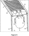
- the radiator (10) whose general view is given in Figure 1 , essentially comprises lateral panels (50a, 50b); a lateral cover (40) which is connected to said lateral panels (50a, 50b); a grid (30) which is seated onto said lateral cover (40) and onto the lateral panels (50a, 50b); and intermediate connection piece (20) which is positioned in the region where said grid (30) and the lateral cover (40) join.
- the grid (30) and the lateral cover (40) are shaped using the roll forming method, and the opening, formed in between, is covered by the intermediate connection piece (20).
- the grid (30) and the lateral cover (40) are connected to each other.
- the grid (30) comprises an upper piece (31) whereon spaces are embodied; and walls (32a, 32b) which are embodied so as to be substantially orthogonal to the upper piece (31) on the edges of the upper piece (31) along the length of said upper piece (31).
- Said connection member (33) is embodied together with the grid (30) and the connection member (33) comprises a connection part (331); a placement part (332); and locking tabs (333a, 333b).
- connection part (331) is the part which connects the grid (30) and said placement part (332).
- Said locking tabs (333a, 333b) are embodied at the end of the placement part (332) as a result of the widening of the placement part (332).
- the lateral cover (40) comprises an upper piece (41); and walls (42a, 42b) embodied so as to be substantially orthogonal to the upper piece (41), on the edges of the upper piece (41) along the length of said upper piece (41).
- fittings connections (44a, 44b) are embodied which extend towards inside of the radiator (10).
- connection member (45) At the vicinity of the lateral cover's (40) end facing the grid (30), there is at least one connection member (45) embodied on the hole part (43).
- Said connection member (45) comprises a placement part (451) and locking tabs (452a, 452b).
- Said locking tabs (452a, 452b) are embodied at the end of the placement part (451) as a result of the widening of the placement part (451).
- the opening formed between the grid (30) and the lateral cover (40) is closed by means of the intermediate connection piece (20) which is made of plastic material.
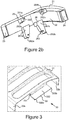
- the intermediate connection piece (20) whose view is given in Figure 2a and 2b , is essentially in the form of a hollow rectangular prism form comprising upper part (21), lateral part (22) and corner parts (23, 24).
- connection member (25) accommodates connection parts (251a, 251b) which connect the connection member (25) and the upper part (21) to each other; and grabbing parts (252a, 252b) which extend substantially orthogonally to said connection parts (251a, 251b) and which are embodied at the continuation of the connection parts (251 a, 251 b) and where the placement part (332) is seated.
- grabbing housing 253 which is defined by the grabbing parts (252a, 252b) and where the placement part (332) extends.
- connection member (26) accommodates connection parts (261a, 261b) which connect the connection member (26) and the lateral part (22) to each other; and grabbing parts (262a, 262b) which extend substantially orthogonally to said connection parts (261a, 261 b) and which are embodied at the continuation of the connection parts (261 a, 261 b) and where the placement part (451) is seated.
- grabbing housing (263) which is defined by the grabbing parts (262a, 262b) and where the placement part (451) extends.
- connection member (25) which exists in the structure of the intermediate connection piece (20
- the intermediate connection piece (20) is connected to the connection member (33) on the grid (30)
- another connection member (26) the intermediate connection piece (20) is connected to the connection member (45) on the lateral cover (40).
- connection parts (251 a, 251 b) of the connection member (25), where the connection member (33) on the grid (30) is placed provide the connection of the intermediate connection piece (20) and the grabbing parts (252a, 252b).
- the grabbing parts (252a, 252b) have a tab form and they hold the placement part (332) of the connection member (33) by encompassing the placement part (332) from two sides.
- the locking tabs (333a, 333b) of the connection member (33) on the grid (30) remain outside of the grabbing parts (252a, 252b) and they prevent the placement part (332) from removing from between the grabbing parts (252a, 252b) by moving backwardly.
- connection parts (261 a, 261 b) of the connection member (26), where the connection member (45) of the lateral cover (40) is placed provide the connection of the intermediate connection piece (20) and the grabbing parts (262a, 262b).
- the grabbing parts (262a, 262b) have an extension form and they hold the placement part (451) of the connection member (45) by encompassing the placement part (451) from two sides. Meanwhile, the placement part (451) is placed inside said grabbing housing (263).
- the locking tabs (452a, 452b) of the connection member (45) remain outside of the grabbing parts (262a, 262b) and they prevent the placement part (451) from removing from between the grabbing parts (262a, 262b) by moving backwardly.
- the connection member (45) of the lateral cover is placed to the grabbing housing (263).
- FIG 8 an alternative embodiment of the grid (30) where the intermediate connection piece (20), whose view is given in Figure 3 , is assembled can be seen.
- the opening (34) of the grid (30) where the connection member (33) is connected is embodied so as to comprise a circular form and so as to be different from the abovementioned grid (30).
- connection member (25) of the grid (30) and correspondingly of the intermediate connection piece (20) extends in the inner volume of the intermediate connection piece (20)
- connection member (26) of the lateral cover (40) and correspondingly of the intermediate connection piece (20) extends in the present inner volume of the radiator (10).
- the subject matter intermediate connection piece (20) is one piece, the production thereof is easier and the cost thereof is lower.
- the lateral panel (50) and the grids (30) can be produced using the roll forming method and using single mould, and this substantially decreases the production costs per product.
Landscapes
- Engineering & Computer Science (AREA)
- Physics & Mathematics (AREA)
- Thermal Sciences (AREA)
- Chemical & Material Sciences (AREA)
- Combustion & Propulsion (AREA)
- Mechanical Engineering (AREA)
- General Engineering & Computer Science (AREA)
- Helmets And Other Head Coverings (AREA)
Applications Claiming Priority (1)
| Application Number | Priority Date | Filing Date | Title |
|---|---|---|---|
| TR201102249 | 2011-03-09 |
Publications (2)
| Publication Number | Publication Date |
|---|---|
| EP2515047A2 true EP2515047A2 (fr) | 2012-10-24 |
| EP2515047A3 EP2515047A3 (fr) | 2014-09-03 |
Family
ID=45833181
Family Applications (1)
| Application Number | Title | Priority Date | Filing Date |
|---|---|---|---|
| EP12158515.2A Withdrawn EP2515047A3 (fr) | 2011-03-09 | 2012-03-08 | Radiateur et pièce de connexion intermédiaire associée |
Country Status (1)
| Country | Link |
|---|---|
| EP (1) | EP2515047A3 (fr) |
Citations (1)
| Publication number | Priority date | Publication date | Assignee | Title |
|---|---|---|---|---|
| EP0863370A2 (fr) | 1997-03-04 | 1998-09-09 | Sigarth AB | Couvercle et élément de couverture pour radiateurs |
Family Cites Families (4)
| Publication number | Priority date | Publication date | Assignee | Title |
|---|---|---|---|---|
| DE8003368U1 (de) * | 1980-02-08 | 1980-05-22 | Gbv Gesellschaft Fuer Beratung Und Vertrieb Technischer Anlagen Mbh & Co Kg, Vorm. Grueter, Grage & Co, 4770 Soest | Verkleidungskoerper fuer einen aus mehreren platten bestehenden heizkoerper |
| DE19832942C1 (de) * | 1998-07-22 | 1999-12-02 | Wiemann Gmbh | Verkleidung für einen Plattenheizkörper mit außenliegendem Betätigungselement |
| DE19832941C1 (de) * | 1998-07-22 | 1999-12-02 | Wiemann Gmbh | Verkleidung für einen Plattenheizkörper mit knopfartigem Rastelement |
| DE19851207A1 (de) * | 1998-11-06 | 2000-05-18 | Wiemann Gmbh | Verkleidung für einen Plattenheizkörper mit Rastelement |
-
2012
- 2012-03-08 EP EP12158515.2A patent/EP2515047A3/fr not_active Withdrawn
Patent Citations (1)
| Publication number | Priority date | Publication date | Assignee | Title |
|---|---|---|---|---|
| EP0863370A2 (fr) | 1997-03-04 | 1998-09-09 | Sigarth AB | Couvercle et élément de couverture pour radiateurs |
Also Published As
| Publication number | Publication date |
|---|---|
| EP2515047A3 (fr) | 2014-09-03 |
Similar Documents
| Publication | Publication Date | Title |
|---|---|---|
| CA2886169C (fr) | Support pour genou | |
| US8975519B2 (en) | Adjustable bracket for steel stud | |
| EP3318684A1 (fr) | Attache à solive dissimulée comportant une ame centrale inclinée | |
| CN104076885B (zh) | 介面卡的支撑固持结构 | |
| WO2008019108A3 (fr) | Système de dossiers suspendus à onglet intégré | |
| EP2080534A3 (fr) | Site médical | |
| US6469904B1 (en) | Housing for computer components | |
| CN109236111A (zh) | 可调节门套及门套安装方法 | |
| EP2515047A2 (fr) | Radiateur et pièce de connexion intermédiaire associée | |
| CN204618144U (zh) | 门体组件和具有它的洗碗机 | |
| CN204177062U (zh) | 冰箱及其后盖板 | |
| JP6182879B2 (ja) | 空気調和機の室外機 | |
| CN107559967A (zh) | 室内机及应用其的空调器 | |
| EP2331766B1 (fr) | Système de toit modulaire et dispositif d'assemblage associé | |
| CN202180997U (zh) | 箱体组装用转角型材 | |
| JP2018033676A (ja) | 水栓カウンター | |
| CN104101074B (zh) | 用于空调器的面板及具有其的空调器壳体 | |
| US20160238168A1 (en) | Duct flange structure, and manufacturing method for the same | |
| CN101431918B (zh) | 用于嵌入式器具的家具布置 | |
| IT202000004975A1 (it) | Gruppo di collegamento di un elemento di copertura ad una struttura di mobile e modulo di mobile comprendente detto gruppo di collegamento | |
| CN205283984U (zh) | 一种连接柱 | |
| CN204902388U (zh) | 后盖装配组件以及具有该后盖装配组件的冰箱 | |
| JP5712829B2 (ja) | 貯湯式給湯機の脚部カバー | |
| EP2290184A1 (fr) | Boîtier d'un ferme-porte | |
| EP2560039A3 (fr) | Endoscope et procédé destiné à la fabrication de l'extrémité distale d'un endoscope |
Legal Events
| Date | Code | Title | Description |
|---|---|---|---|
| PUAI | Public reference made under article 153(3) epc to a published international application that has entered the european phase |
Free format text: ORIGINAL CODE: 0009012 |
|
| AK | Designated contracting states |
Kind code of ref document: A2 Designated state(s): AL AT BE BG CH CY CZ DE DK EE ES FI FR GB GR HR HU IE IS IT LI LT LU LV MC MK MT NL NO PL PT RO RS SE SI SK SM TR |
|
| AX | Request for extension of the european patent |
Extension state: BA ME |
|
| PUAL | Search report despatched |
Free format text: ORIGINAL CODE: 0009013 |
|
| AK | Designated contracting states |
Kind code of ref document: A3 Designated state(s): AL AT BE BG CH CY CZ DE DK EE ES FI FR GB GR HR HU IE IS IT LI LT LU LV MC MK MT NL NO PL PT RO RS SE SI SK SM TR |
|
| AX | Request for extension of the european patent |
Extension state: BA ME |
|
| RIC1 | Information provided on ipc code assigned before grant |
Ipc: F24D 19/06 20060101AFI20140730BHEP |
|
| STAA | Information on the status of an ep patent application or granted ep patent |
Free format text: STATUS: THE APPLICATION IS DEEMED TO BE WITHDRAWN |
|
| 18D | Application deemed to be withdrawn |
Effective date: 20150304 |