EP2515073A2 - Verfahren und System zur Positionierung eines Laservibrometers während einer kontaktfreien Abtastung - Google Patents
Verfahren und System zur Positionierung eines Laservibrometers während einer kontaktfreien Abtastung Download PDFInfo
- Publication number
- EP2515073A2 EP2515073A2 EP12164749A EP12164749A EP2515073A2 EP 2515073 A2 EP2515073 A2 EP 2515073A2 EP 12164749 A EP12164749 A EP 12164749A EP 12164749 A EP12164749 A EP 12164749A EP 2515073 A2 EP2515073 A2 EP 2515073A2
- Authority
- EP
- European Patent Office
- Prior art keywords
- object surface
- light
- reflection
- vibrometer
- intensity
- Prior art date
- Legal status (The legal status is an assumption and is not a legal conclusion. Google has not performed a legal analysis and makes no representation as to the accuracy of the status listed.)
- Granted
Links
Images


Classifications
-
- G—PHYSICS
- G01—MEASURING; TESTING
- G01B—MEASURING LENGTH, THICKNESS OR SIMILAR LINEAR DIMENSIONS; MEASURING ANGLES; MEASURING AREAS; MEASURING IRREGULARITIES OF SURFACES OR CONTOURS
- G01B11/00—Measuring arrangements characterised by the use of optical techniques
- G01B11/24—Measuring arrangements characterised by the use of optical techniques for measuring contours or curvatures
- G01B11/25—Measuring arrangements characterised by the use of optical techniques for measuring contours or curvatures by projecting a pattern, e.g. one or more lines, moiré fringes on the object
-
- G—PHYSICS
- G01—MEASURING; TESTING
- G01B—MEASURING LENGTH, THICKNESS OR SIMILAR LINEAR DIMENSIONS; MEASURING ANGLES; MEASURING AREAS; MEASURING IRREGULARITIES OF SURFACES OR CONTOURS
- G01B11/00—Measuring arrangements characterised by the use of optical techniques
- G01B11/16—Measuring arrangements characterised by the use of optical techniques for measuring the deformation in a solid, e.g. optical strain gauge
- G01B11/161—Measuring arrangements characterised by the use of optical techniques for measuring the deformation in a solid, e.g. optical strain gauge by interferometric means
-
- G—PHYSICS
- G01—MEASURING; TESTING
- G01B—MEASURING LENGTH, THICKNESS OR SIMILAR LINEAR DIMENSIONS; MEASURING ANGLES; MEASURING AREAS; MEASURING IRREGULARITIES OF SURFACES OR CONTOURS
- G01B11/00—Measuring arrangements characterised by the use of optical techniques
- G01B11/24—Measuring arrangements characterised by the use of optical techniques for measuring contours or curvatures
- G01B11/25—Measuring arrangements characterised by the use of optical techniques for measuring contours or curvatures by projecting a pattern, e.g. one or more lines, moiré fringes on the object
- G01B11/2545—Measuring arrangements characterised by the use of optical techniques for measuring contours or curvatures by projecting a pattern, e.g. one or more lines, moiré fringes on the object with one projection direction and several detection directions, e.g. stereo
Definitions
- This disclosure relates generally to non-contact scanning and, more particularly, to a method and system for spatially locating a laser vibrometer relative to an object.
- Machinery components or objects can be inspected using non-contact scanning. Vibrationally induced deflections and stresses of the component, for example, can be determined using data measured by a laser vibrometer. The deflections and stresses can subsequently be processed to predict or model how the component will respond to vibrations during operation of the component within the machinery (e.g., performance of the rotor blade within the gas turbine engine). In order to produce accurate predictions and models, however, the position of the vibrometer and, thus, the position of where the data is being measured on the component surface must be located relative to the component.
- the vibrometer can be located, for example, by (i) mechanically aligning the vibrometer and the rotor blade in known positions, or (ii) performing post processing alignment procedures such as, for example, normalizing measurement data to a normal or reference coordinate space. Both methods for locating the vibrometer, however, require certain base assumptions (e.g., that the component is close to a nominal geometric location and shape, that the surface of the component can be represented by a two dimensional planar surface, that non-scalar image data can be used as a reference, etc.) and can increase time and costs associated with performing the inspection.
- base assumptions e.g., that the component is close to a nominal geometric location and shape, that the surface of the component can be represented by a two dimensional planar surface, that non-scalar image data can be used as a reference, etc.
- a method for inspecting a surface of an object with an optical scanner and a laser vibrometer.
- the method includes the steps of: (a) mapping at least a portion of the object surface using the optical scanner; (b) projecting a beam of light from the laser vibrometer onto the object surface at a measurement point; (c) locating the measurement point relative to the object surface using the optical scanner; and (d) measuring a position of the object surface using the laser vibrometer.
- a system for inspecting a surface of an object includes a laser vibrometer, an optical scanner and a controller.
- the vibrometer is adapted to project a beam of light onto the object surface at a measurement point, and to measure a position of the object surface.
- the optical scanner is adapted to map at least a portion of the object surface, and to locate the measurement point relative to the object surface.
- the controller is adapted to correlate the measured position of the object surface to the location of the measurement point.
- FIG. 1 illustrates a system 10 for inspecting a surface 12 of an object such as a rotor blade, generally referred to hereinafter as an "object 14".
- the system includes an optical scanner 16, a laser vibrometer 18, an excitation system 20, a support stand 22 and a controller 23.
- the optical scanner 16 is adapted to map at least a portion of the object surface 12.
- the term "map" is used herein to describe a process of applying a triangulated mesh of surface points to an object surface.
- the optical scanner 16 includes a fringe pattern projector 24 and one or more cameras 26.
- the projector 24 is adapted to project a point, line and/or pattern of light at one or more projection frequencies.
- Each camera 26 is adapted to capture an image within a light intensity band and a camera frequency band, which camera frequency band includes the projection frequencies.
- An example of such a projector and cameras is disclosed in U.S. Patent Application Publication No. 2009/0033947 .
- the position of the projected mesh can be located relative to the object in several ways.
- the vibrometer 18 (also sometimes referred to as a "laser Doppler vibrometer” or an “interferometer”) is adapted to measure a relative spatial position of the object surface 12.
- the vibrometer 18 includes a laser 28 and a light detector 30.
- the laser 28 is adapted to project a beam of light 32 at a vibrometer frequency and a vibrometer light intensity.
- the light detector 30 is adapted to detect a reflection of the beam of light 32 having a reflection frequency.
- the vibrometer frequency is selected such that the reflection frequency is outside (e.g., greater than) the camera frequency band.
- the excitation system 20 is adapted to induce vibrations in at least a portion of the object 14.
- the excitation system 20 includes a loudspeaker 34 adapted to transmit an audio excitation signal.
- the support stand 22 includes a base 36, an object turntable 38, an excitation system turntable 40, an object support 42 and sensor mounting stand 44.
- the base 36 includes a lower platform 46 and an upper platform 48.
- the upper platform 48 has an aperture 50 that extends along an axis 52.
- the object turntable 38 is mounted to the lower platform 46, and is adapted to rotate about the axis 52.
- the excitation system turntable 40 is mounted to the upper platform 48, and is adapted to rotate about the axis 52.
- the excitation system turntable 40 includes a central aperture 54 that extends along the axis 52.
- the object support 42 extends along the axis 52 from the object turntable 38, through the apertures 50 and 54, to an object support surface 56.
- the sensor mounting stand 44 includes a vibrometer mount 58 and a scanner mount 60. The sensor mounting stand 44 extends from the upper platform 48 to the vibrometer mount 58.
- the optical scanner 16 is connected to scanner mount 60.
- the vibrometer 18 is connected to the vibrometer mount 58.
- the loudspeaker 34 is connected to the excitation system turntable 40.
- the controller 23 can be implemented using hardware, software, or a combination thereof.
- the hardware can include one or more processors, analog and/or digital circuitry, etc.
- the controller can include one or more sub-processors (not shown) respectively configured with the optical scanner 16 and the vibrometer 18.
- the controller is in signal communication (e.g., hardwired or wirelessly connected) with the optical scanner 16, the vibrometer 18, the loudspeaker 34, the object turntable 38 and the excitation system turntable 40.
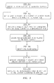
- FIG. 3 illustrates a flow diagram of a method for inspecting at least a portion of the surface 12 of the object 14 (see FIG. 1 ).
- the object 14 can be configured as, for example, a component of a gas turbine engine such as an integral bladed rotor (also referred to as an "IBR").
- IBR integral bladed rotor
- the object will be referred to hereinafter as the rotor 14.
- the rotor 14 includes a hub 62 and a plurality of blades 64 and 66.
- the present invention is not limited to inspecting any particular object configuration and/or composition.
- the rotor hub 62 is disposed on the object support surface 56 such that, for example, a rotational axis of the hub 62 is aligned with the rotational axis 52 of the turntable 38.
- the controller signals the optical scanner 16 to map the surface 12 of a first one of the rotor blades 64.
- the projector 24 for example, can project a pattern of alternating parallel light (e.g., white, or any other suitable color) and dark (e.g., black) lines onto the blade surface 12.
- the lines may be distorted by contours, edges and/or other features (e.g., apertures) of the blade surface 12.
- Images of the lines on the blade surface 12 are captured by the cameras 26, and processed by, for example, one of the controller sub-processors to provide a three-dimensional model of the blade surface 12.
- step 304 the controller signals the vibrometer 18 to project the beam of light 32 from the laser onto the blade surface 12 at a measurement point 68.
- the controller signals the optical scanner 16 to locate the measurement point 68 created by the laser and, thus, a location of where the beam of light 32 reflects against the blade surface 12.
- the cameras 26 capture images of the blade surface 12, which images are overexposed (e.g., missing image data) around the measurement point 68.
- the overexposure can be caused, for example, by the intensity and/or frequency of the reflected light being outside the detection capabilities of the cameras 26; e.g., where the intensity of the reflected light is outside the light intensity band of the cameras 26, and/or where the frequency of the reflected light is outside the frequency band of the cameras 26.
- the cameras 26 therefore do not capture image data from the light beam reflection point.
- the blade surface images can be processed by, for example, one of the controller sub-processors to provide a three-dimensional model of the blade surface 12 as shown in FIG. 4 .
- the laser light reflection can be identified on the 3D model via the missing image data 70 (see FIG. 4 ).
- the measurement point 68 can subsequently be located using the model, for example, by (i) determining a centroid 72 of the reflection (i.e., the missing image data 70), and (ii) determining the spatial location of the centroid 72 relative to the mapped blade surface 12.
- the reflection can be identified via its intensity, color, shape, etc. where the reflection frequency is within the camera frequency band; i.e., the cameras 26 can capture image data from the reflection.
- photogrammetry can be used to locate the position of where the beam of light 32 reflects against the blade surface 12.
- step 308 the controller signals the loudspeaker 34 to transmit the excitation signal towards an underside of the first rotor blade 64 to induce a vibratory response.
- the controller signals the vibrometer 18 to measure vibrationally induced blade deflections and associated blade stresses in the first rotor blade 64 at the measurement point 68.
- the laser 28 for example, projects the beam of light 32 onto the blade surface 12 at the vibrometer frequency.
- the light detector 30 is used to determine the reflection frequency of the reflection. Doppler shifts between the vibrometer and reflection frequencies caused by the deflections can subsequently be determined to provide data indicative of a position of the blade surface 12 (e.g., a distance between the blade surface 12 and the vibrometer 18) at a particular point in time. Additional measurements can be performed over a period of time, and processed to measure the deflections and stresses caused by the deflections using known techniques.
- step 312 the controller correlates the measurements taken in step 310 to the location determined in step 306 of the measurement point 68 and, thus, the location of where the beam of light 32 reflects against the blade surface 12.
- the controller can generate output data indicative of both the measurements and the location of where the measurements were taken relative to the blade surface 12 (e.g., the blade edges) without performing mechanical or post processing alignment procedures. In some embodiments, however, such alignment procedures can be performed, for example, to verify system accuracy. Subsequent processing of the output data by the controller or another computer system, therefore, can be performed to accurately predict or model how the rotor blade 64 will respond to vibrations during operation of an engine.
- steps 302 to 306 may be performed together such that the blade surface 12 is mapped and the measurement point 68 is located without performing multiple scans with the optical scanner 16.
- the vibrometer 18 can perform additional measurements at one or more alternate locations on the blade surface 12 by adjusting the position of the object turntable 38 or the vibrometer mount 58 relative to the measurement point 68.
- the additional measurements are subsequently correlated to the locations of where the beam of light 32 was focused on the blade surface 12 during those measurements.
- the locations may be determined by adding a vector indicative of the distance and direction the object turntable or the vibrometer mount were moved to the spatial location of the measurement point 68 determined in step 306.
Landscapes
- Physics & Mathematics (AREA)
- General Physics & Mathematics (AREA)
- Engineering & Computer Science (AREA)
- Computer Vision & Pattern Recognition (AREA)
- Length Measuring Devices By Optical Means (AREA)
- Measurement Of Mechanical Vibrations Or Ultrasonic Waves (AREA)
Applications Claiming Priority (1)
| Application Number | Priority Date | Filing Date | Title |
|---|---|---|---|
| US13/090,815 US8899115B2 (en) | 2011-04-20 | 2011-04-20 | Method and system for locating a laser vibrometer during non-contact scanning |
Publications (3)
| Publication Number | Publication Date |
|---|---|
| EP2515073A2 true EP2515073A2 (de) | 2012-10-24 |
| EP2515073A3 EP2515073A3 (de) | 2016-07-06 |
| EP2515073B1 EP2515073B1 (de) | 2017-11-15 |
Family
ID=46085373
Family Applications (1)
| Application Number | Title | Priority Date | Filing Date |
|---|---|---|---|
| EP12164749.9A Active EP2515073B1 (de) | 2011-04-20 | 2012-04-19 | Verfahren und System zur Inspektion der Oberfläche eines Objekts mittels eines optischen Scanners und eines Laservibrometers |
Country Status (2)
| Country | Link |
|---|---|
| US (1) | US8899115B2 (de) |
| EP (1) | EP2515073B1 (de) |
Cited By (3)
| Publication number | Priority date | Publication date | Assignee | Title |
|---|---|---|---|---|
| WO2019233701A1 (de) | 2018-06-04 | 2019-12-12 | Deutsches Zentrum für Luft- und Raumfahrt e.V. | Verfahren und vorrichtung zum messen von schwingungen eines objekts unter verwendung einer drohne |
| WO2019238508A1 (de) * | 2018-06-15 | 2019-12-19 | Polytec Gmbh | Abgleichverfahren für eine strahlrichteinheit einer interferometrischen messvorrichtung und messvorrichtung zur durchführung einer interferometrischen messung mittels laserstrahlung |
| CN110617876A (zh) * | 2019-11-01 | 2019-12-27 | 云南电网有限责任公司电力科学研究院 | 电力设备异响定位方法 |
Families Citing this family (16)
| Publication number | Priority date | Publication date | Assignee | Title |
|---|---|---|---|---|
| US8621931B2 (en) * | 2011-03-22 | 2014-01-07 | Dso National Laboratories | Multipoint laser vibrometer with single detector |
| US20130003071A1 (en) * | 2011-06-30 | 2013-01-03 | Catch the Wind, Inc. | System and Method of In Situ Wind Turbine Blade Monitoring |
| FR3043193B1 (fr) | 2015-11-02 | 2019-04-19 | Mesure-Systems3D | Dispositif de controle tridimensionnel sans contact d’une piece mecanique a denture |
| FR3043194B1 (fr) * | 2015-11-02 | 2019-04-19 | Mesure-Systems3D | Dispositif de controle tridimensionnel sans contact de pale pour turbomachine, en particulier pour reacteur ou turbine d’aeronef |
| US9733195B2 (en) * | 2015-12-18 | 2017-08-15 | General Electric Company | System and method for inspecting turbine blades |
| US20170265751A1 (en) * | 2016-03-17 | 2017-09-21 | Massachusetts Institute Of Technology | Non-contact laser ultrasound system |
| DE102018114478B4 (de) * | 2018-06-15 | 2024-09-19 | Polytec Gmbh | Verfahren zur Bestimmung des Strahlverlaufs eines Messstrahls einer interferometrischen Messvorrichtung und Messvorrichtung zur interferometrischen Vermessung eines Messobjekts |
| DE102018114479B3 (de) * | 2018-06-15 | 2019-11-14 | Polytec Gmbh | Verfahren zur Bestimmung des Strahlverlaufs eines Messstrahls einer Interferometrischen Messvorrichtung und Messvorrichtung zur interferometrischen Vermessung eines Messobjekts |
| CN108709625B (zh) * | 2018-06-25 | 2024-01-30 | 华南理工大学 | 双铺开太阳翼振动测量装置及方法 |
| CN109269623A (zh) * | 2018-09-18 | 2019-01-25 | 浙江工业大学 | 一种基于摄像头的板结构振动测量装置 |
| CN110763325A (zh) * | 2019-10-24 | 2020-02-07 | 国家电网有限公司 | 基于激光测振的变压器振动测量装置及方法 |
| DE102019219387A1 (de) * | 2019-12-11 | 2021-06-17 | MTU Aero Engines AG | Verfahren und vorrichtung zum bestimmen von aufwertefaktoren für dehnungsmessungen an maschinenelementen |
| US11650130B1 (en) * | 2020-10-22 | 2023-05-16 | United States Of America As Represented By The Secretary Of The Air Force | Method and system for improving strain gauge to blade tip timing correlation |
| JP7747053B2 (ja) * | 2021-09-28 | 2025-10-01 | 株式会社Ihi | ブリスクの振動検出装置 |
| US12209997B2 (en) * | 2022-04-26 | 2025-01-28 | Rtx Corporation | Inspection systems and methods for sealing surfaces |
| DE102024124236A1 (de) * | 2024-08-23 | 2026-02-26 | Polytec Gmbh | Verfahren und vorrichtung zur berührungslosen schwingungsmessung |
Citations (1)
| Publication number | Priority date | Publication date | Assignee | Title |
|---|---|---|---|---|
| US20090033947A1 (en) | 2007-07-31 | 2009-02-05 | United Technologies Corporation | Method for repeatable optical determination of object geometry dimensions and deviations |
Family Cites Families (25)
| Publication number | Priority date | Publication date | Assignee | Title |
|---|---|---|---|---|
| US3667846A (en) * | 1969-07-28 | 1972-06-06 | Charles Nater | Optical surface inspection apparatus |
| US4554836A (en) * | 1984-08-31 | 1985-11-26 | The United States Of America As Represented By The Secretary Of The Navy | Laser vibrometer |
| CH684212A5 (fr) | 1990-10-16 | 1994-07-29 | Suisse Electronique Microtech | Dispositif optique à interférométrie en lumière blanche. |
| US7098435B2 (en) * | 1996-10-25 | 2006-08-29 | Frederick E. Mueller | Method and apparatus for scanning three-dimensional objects |
| DE19861203B4 (de) * | 1998-02-16 | 2004-01-29 | Polytec Gmbh | Verfahren und Vorrichtun gzur flächenhaften Schwingungsanalyse |
| US6999073B1 (en) * | 1998-07-20 | 2006-02-14 | Geometrix, Inc. | Method and system for generating fully-textured 3D |
| CA2279609C (en) * | 1998-08-06 | 2007-05-01 | Voith Sulzer Papiertechnik Patent Gmbh | Device to actively weaken undesirable vibrations in a rotating roll; device for treatment of a material web; specifically a paper or cardboard web |
| US6271924B1 (en) | 1998-12-29 | 2001-08-07 | Bryan Kok Ann Ngoi | Noncontact acoustic optic scanning laser vibrometer for determining the difference between an object and a reference surface |
| US6246638B1 (en) * | 1999-03-30 | 2001-06-12 | Honeywell International Inc. | Fiber-optic vibration sensor based on frequency modulation of light-excited oscillators |
| US7157649B2 (en) * | 1999-12-23 | 2007-01-02 | New Transducers Limited | Contact sensitive device |
| GB0009311D0 (en) * | 2000-04-17 | 2000-05-31 | Logica Uk Ltd | Vibration analysis |
| JP3982267B2 (ja) * | 2002-01-16 | 2007-09-26 | 株式会社村田製作所 | 積層型圧電セラミック素子の製造方法 |
| EP1431740B1 (de) * | 2002-12-16 | 2006-03-08 | Polytec GmbH | Messvorrichtung zum berührungslosen Erfassen von Schwingungen eines Objektes |
| US7460250B2 (en) * | 2003-10-24 | 2008-12-02 | 3Dm Devices Inc. | Laser triangulation system |
| DE10351698A1 (de) * | 2003-11-05 | 2005-06-30 | Minebea Co., Ltd. | Meßverfahren zur Bestimmung der Geräuschemission eines Elektromotors und Meßvorrichtung |
| US7024787B2 (en) | 2004-04-01 | 2006-04-11 | United Technologies Corporation | Template for evaluating parts and method of using same |
| US7064811B2 (en) * | 2004-05-20 | 2006-06-20 | Siemens Power Generation, Inc. | Imaging rotating turbine blades in a gas turbine engine |
| DE102007023826A1 (de) * | 2007-05-21 | 2008-11-27 | Polytec Gmbh | Verfahren und Vorrichtung zur berührungslosen Schwingungsmessung |
| US7836772B2 (en) | 2007-09-26 | 2010-11-23 | Siemens Energy, Inc. | Method and apparatus for tracking a rotating blade tip for blade vibration monitor measurements |
| US7654145B2 (en) * | 2007-09-27 | 2010-02-02 | Siemens Energy, Inc. | Non-synchronous vibrational excitation of turbine blades using a rotating excitation structure |
| US7578178B2 (en) | 2007-09-28 | 2009-08-25 | United Technologies Corporation | Method of inspecting turbine internal cooling features using non-contact scanners |
| US7869026B2 (en) | 2007-12-21 | 2011-01-11 | United Technologies Corp. | Targeted artifacts and methods for evaluating 3-D coordinate system measurement accuracy of optical 3-D measuring systems using such targeted artifacts |
| US7778788B2 (en) | 2008-05-29 | 2010-08-17 | United Technologies Corporation | Scanner based optical inspection system |
| US7573586B1 (en) | 2008-06-02 | 2009-08-11 | United Technologies Corporation | Method and system for measuring a coating thickness |
| WO2011068582A2 (en) * | 2009-09-18 | 2011-06-09 | Logos Technologies, Inc. | Systems and methods for persistent surveillance and large volume data streaming |
-
2011
- 2011-04-20 US US13/090,815 patent/US8899115B2/en active Active
-
2012
- 2012-04-19 EP EP12164749.9A patent/EP2515073B1/de active Active
Patent Citations (1)
| Publication number | Priority date | Publication date | Assignee | Title |
|---|---|---|---|---|
| US20090033947A1 (en) | 2007-07-31 | 2009-02-05 | United Technologies Corporation | Method for repeatable optical determination of object geometry dimensions and deviations |
Cited By (5)
| Publication number | Priority date | Publication date | Assignee | Title |
|---|---|---|---|---|
| WO2019233701A1 (de) | 2018-06-04 | 2019-12-12 | Deutsches Zentrum für Luft- und Raumfahrt e.V. | Verfahren und vorrichtung zum messen von schwingungen eines objekts unter verwendung einer drohne |
| WO2019238508A1 (de) * | 2018-06-15 | 2019-12-19 | Polytec Gmbh | Abgleichverfahren für eine strahlrichteinheit einer interferometrischen messvorrichtung und messvorrichtung zur durchführung einer interferometrischen messung mittels laserstrahlung |
| US11333485B2 (en) | 2018-06-15 | 2022-05-17 | Polytec Gmbh | Alignment method for a beam-directing unit of an interferometric measuring device, and measuring device for carrying out an interferometric measurement by means of laser radiation |
| CN110617876A (zh) * | 2019-11-01 | 2019-12-27 | 云南电网有限责任公司电力科学研究院 | 电力设备异响定位方法 |
| CN110617876B (zh) * | 2019-11-01 | 2021-10-22 | 云南电网有限责任公司电力科学研究院 | 电力设备异响定位方法 |
Also Published As
| Publication number | Publication date |
|---|---|
| US8899115B2 (en) | 2014-12-02 |
| US20120266680A1 (en) | 2012-10-25 |
| EP2515073A3 (de) | 2016-07-06 |
| EP2515073B1 (de) | 2017-11-15 |
Similar Documents
| Publication | Publication Date | Title |
|---|---|---|
| EP2515073B1 (de) | Verfahren und System zur Inspektion der Oberfläche eines Objekts mittels eines optischen Scanners und eines Laservibrometers | |
| Barone et al. | Low-frame-rate single camera system for 3D full-field high-frequency vibration measurements | |
| CN102077052B (zh) | 用于超声波检查的扫描计划的视觉系统 | |
| CA2833383C (en) | Device and method for determining the position of two coupled shafts with respect to each other | |
| Gwashavanhu et al. | Rotating blade vibration analysis using photogrammetry and tracking laser Doppler vibrometry | |
| KR101293040B1 (ko) | 1대의 진동 측정기를 이용한 3차원 진동 측정 방법 및 시스템 | |
| CN102016565A (zh) | 用于将三维模型配准到表现零件姿态的点数据的系统、程序产品、和相关方法 | |
| EP3377848B1 (de) | Optische interferometrie | |
| JP2016057063A (ja) | 測定対象物の非接触検知方法及びその装置 | |
| US20200370947A1 (en) | Devices and methods for vibration analysis | |
| JP5923054B2 (ja) | 形状検査装置 | |
| JP2005283440A (ja) | 振動計測装置及びその計測方法 | |
| CN110617876B (zh) | 电力设备异响定位方法 | |
| Wang et al. | High precision full-field vibration measurement by LDV-induced stroboscopic fringe projection | |
| US20230204409A1 (en) | System and non-contact method for measuring vibration on surface of an object | |
| JP5133095B2 (ja) | 超音波ガスメーター部品の検査方法及びその装置 | |
| Barone et al. | 3D vibration measurements by a virtual-stereo-camera system based on a single low frame rate camera | |
| Barone et al. | Optical stereo-system for full-field high-frequency 3D vibration measurements based on low-frame-rate cameras | |
| WO2021111533A1 (ja) | 異常判定装置、異常判定方法およびプログラム記憶媒体 | |
| JP5688738B2 (ja) | 微小孔の検査装置およびその検査方法 | |
| US20250354857A1 (en) | System And Method For Measuring Oscillations And Characterizing Surface Geometry Of Reflective Surfaces By Reflecting Light Onto An Image Capture Screen | |
| US20250078287A1 (en) | State determination apparatus, state determination method, and computer-readable recording medium | |
| Barone et al. | Optical Stereo-System for Full-Field High-Frequency 3D Vibration Measurements Based | |
| KR20260030586A (ko) | 라이다 장치의 각 해상도 검사 장치 및 방법 | |
| WO2024249191A1 (en) | System and method for characterizing surface geometry and measuring oscillations using spatial and temporal correlations of high frequency displacement measurements made with diffusively reflected light beams |
Legal Events
| Date | Code | Title | Description |
|---|---|---|---|
| PUAI | Public reference made under article 153(3) epc to a published international application that has entered the european phase |
Free format text: ORIGINAL CODE: 0009012 |
|
| AK | Designated contracting states |
Kind code of ref document: A2 Designated state(s): AL AT BE BG CH CY CZ DE DK EE ES FI FR GB GR HR HU IE IS IT LI LT LU LV MC MK MT NL NO PL PT RO RS SE SI SK SM TR |
|
| AX | Request for extension of the european patent |
Extension state: BA ME |
|
| PUAL | Search report despatched |
Free format text: ORIGINAL CODE: 0009013 |
|
| AK | Designated contracting states |
Kind code of ref document: A3 Designated state(s): AL AT BE BG CH CY CZ DE DK EE ES FI FR GB GR HR HU IE IS IT LI LT LU LV MC MK MT NL NO PL PT RO RS SE SI SK SM TR |
|
| AX | Request for extension of the european patent |
Extension state: BA ME |
|
| RIC1 | Information provided on ipc code assigned before grant |
Ipc: G01B 11/25 20060101ALI20160531BHEP Ipc: G01B 11/16 20060101AFI20160531BHEP |
|
| RAP1 | Party data changed (applicant data changed or rights of an application transferred) |
Owner name: UNITED TECHNOLOGIES CORPORATION |
|
| STAA | Information on the status of an ep patent application or granted ep patent |
Free format text: STATUS: REQUEST FOR EXAMINATION WAS MADE |
|
| 17P | Request for examination filed |
Effective date: 20170106 |
|
| RBV | Designated contracting states (corrected) |
Designated state(s): AL AT BE BG CH CY CZ DE DK EE ES FI FR GB GR HR HU IE IS IT LI LT LU LV MC MK MT NL NO PL PT RO RS SE SI SK SM TR |
|
| GRAP | Despatch of communication of intention to grant a patent |
Free format text: ORIGINAL CODE: EPIDOSNIGR1 |
|
| STAA | Information on the status of an ep patent application or granted ep patent |
Free format text: STATUS: GRANT OF PATENT IS INTENDED |
|
| INTG | Intention to grant announced |
Effective date: 20170523 |
|
| GRAS | Grant fee paid |
Free format text: ORIGINAL CODE: EPIDOSNIGR3 |
|
| GRAA | (expected) grant |
Free format text: ORIGINAL CODE: 0009210 |
|
| STAA | Information on the status of an ep patent application or granted ep patent |
Free format text: STATUS: THE PATENT HAS BEEN GRANTED |
|
| AK | Designated contracting states |
Kind code of ref document: B1 Designated state(s): AL AT BE BG CH CY CZ DE DK EE ES FI FR GB GR HR HU IE IS IT LI LT LU LV MC MK MT NL NO PL PT RO RS SE SI SK SM TR |
|
| REG | Reference to a national code |
Ref country code: CH Ref legal event code: EP Ref country code: GB Ref legal event code: FG4D Ref country code: AT Ref legal event code: REF Ref document number: 946719 Country of ref document: AT Kind code of ref document: T Effective date: 20171115 |
|
| REG | Reference to a national code |
Ref country code: IE Ref legal event code: FG4D |
|
| REG | Reference to a national code |
Ref country code: DE Ref legal event code: R096 Ref document number: 602012039691 Country of ref document: DE |
|
| REG | Reference to a national code |
Ref country code: NL Ref legal event code: MP Effective date: 20171115 |
|
| REG | Reference to a national code |
Ref country code: FR Ref legal event code: PLFP Year of fee payment: 7 |
|
| REG | Reference to a national code |
Ref country code: LT Ref legal event code: MG4D |
|
| REG | Reference to a national code |
Ref country code: AT Ref legal event code: MK05 Ref document number: 946719 Country of ref document: AT Kind code of ref document: T Effective date: 20171115 |
|
| PG25 | Lapsed in a contracting state [announced via postgrant information from national office to epo] |
Ref country code: ES Free format text: LAPSE BECAUSE OF FAILURE TO SUBMIT A TRANSLATION OF THE DESCRIPTION OR TO PAY THE FEE WITHIN THE PRESCRIBED TIME-LIMIT Effective date: 20171115 Ref country code: NO Free format text: LAPSE BECAUSE OF FAILURE TO SUBMIT A TRANSLATION OF THE DESCRIPTION OR TO PAY THE FEE WITHIN THE PRESCRIBED TIME-LIMIT Effective date: 20180215 Ref country code: SE Free format text: LAPSE BECAUSE OF FAILURE TO SUBMIT A TRANSLATION OF THE DESCRIPTION OR TO PAY THE FEE WITHIN THE PRESCRIBED TIME-LIMIT Effective date: 20171115 Ref country code: LT Free format text: LAPSE BECAUSE OF FAILURE TO SUBMIT A TRANSLATION OF THE DESCRIPTION OR TO PAY THE FEE WITHIN THE PRESCRIBED TIME-LIMIT Effective date: 20171115 Ref country code: FI Free format text: LAPSE BECAUSE OF FAILURE TO SUBMIT A TRANSLATION OF THE DESCRIPTION OR TO PAY THE FEE WITHIN THE PRESCRIBED TIME-LIMIT Effective date: 20171115 Ref country code: NL Free format text: LAPSE BECAUSE OF FAILURE TO SUBMIT A TRANSLATION OF THE DESCRIPTION OR TO PAY THE FEE WITHIN THE PRESCRIBED TIME-LIMIT Effective date: 20171115 |
|
| PG25 | Lapsed in a contracting state [announced via postgrant information from national office to epo] |
Ref country code: HR Free format text: LAPSE BECAUSE OF FAILURE TO SUBMIT A TRANSLATION OF THE DESCRIPTION OR TO PAY THE FEE WITHIN THE PRESCRIBED TIME-LIMIT Effective date: 20171115 Ref country code: BG Free format text: LAPSE BECAUSE OF FAILURE TO SUBMIT A TRANSLATION OF THE DESCRIPTION OR TO PAY THE FEE WITHIN THE PRESCRIBED TIME-LIMIT Effective date: 20180215 Ref country code: GR Free format text: LAPSE BECAUSE OF FAILURE TO SUBMIT A TRANSLATION OF THE DESCRIPTION OR TO PAY THE FEE WITHIN THE PRESCRIBED TIME-LIMIT Effective date: 20180216 Ref country code: RS Free format text: LAPSE BECAUSE OF FAILURE TO SUBMIT A TRANSLATION OF THE DESCRIPTION OR TO PAY THE FEE WITHIN THE PRESCRIBED TIME-LIMIT Effective date: 20171115 Ref country code: AT Free format text: LAPSE BECAUSE OF FAILURE TO SUBMIT A TRANSLATION OF THE DESCRIPTION OR TO PAY THE FEE WITHIN THE PRESCRIBED TIME-LIMIT Effective date: 20171115 Ref country code: LV Free format text: LAPSE BECAUSE OF FAILURE TO SUBMIT A TRANSLATION OF THE DESCRIPTION OR TO PAY THE FEE WITHIN THE PRESCRIBED TIME-LIMIT Effective date: 20171115 |
|
| PG25 | Lapsed in a contracting state [announced via postgrant information from national office to epo] |
Ref country code: EE Free format text: LAPSE BECAUSE OF FAILURE TO SUBMIT A TRANSLATION OF THE DESCRIPTION OR TO PAY THE FEE WITHIN THE PRESCRIBED TIME-LIMIT Effective date: 20171115 Ref country code: CY Free format text: LAPSE BECAUSE OF FAILURE TO SUBMIT A TRANSLATION OF THE DESCRIPTION OR TO PAY THE FEE WITHIN THE PRESCRIBED TIME-LIMIT Effective date: 20171115 Ref country code: CZ Free format text: LAPSE BECAUSE OF FAILURE TO SUBMIT A TRANSLATION OF THE DESCRIPTION OR TO PAY THE FEE WITHIN THE PRESCRIBED TIME-LIMIT Effective date: 20171115 Ref country code: SK Free format text: LAPSE BECAUSE OF FAILURE TO SUBMIT A TRANSLATION OF THE DESCRIPTION OR TO PAY THE FEE WITHIN THE PRESCRIBED TIME-LIMIT Effective date: 20171115 Ref country code: DK Free format text: LAPSE BECAUSE OF FAILURE TO SUBMIT A TRANSLATION OF THE DESCRIPTION OR TO PAY THE FEE WITHIN THE PRESCRIBED TIME-LIMIT Effective date: 20171115 |
|
| REG | Reference to a national code |
Ref country code: DE Ref legal event code: R097 Ref document number: 602012039691 Country of ref document: DE |
|
| PG25 | Lapsed in a contracting state [announced via postgrant information from national office to epo] |
Ref country code: PL Free format text: LAPSE BECAUSE OF FAILURE TO SUBMIT A TRANSLATION OF THE DESCRIPTION OR TO PAY THE FEE WITHIN THE PRESCRIBED TIME-LIMIT Effective date: 20171115 Ref country code: RO Free format text: LAPSE BECAUSE OF FAILURE TO SUBMIT A TRANSLATION OF THE DESCRIPTION OR TO PAY THE FEE WITHIN THE PRESCRIBED TIME-LIMIT Effective date: 20171115 Ref country code: SM Free format text: LAPSE BECAUSE OF FAILURE TO SUBMIT A TRANSLATION OF THE DESCRIPTION OR TO PAY THE FEE WITHIN THE PRESCRIBED TIME-LIMIT Effective date: 20171115 Ref country code: IT Free format text: LAPSE BECAUSE OF FAILURE TO SUBMIT A TRANSLATION OF THE DESCRIPTION OR TO PAY THE FEE WITHIN THE PRESCRIBED TIME-LIMIT Effective date: 20171115 |
|
| PLBE | No opposition filed within time limit |
Free format text: ORIGINAL CODE: 0009261 |
|
| STAA | Information on the status of an ep patent application or granted ep patent |
Free format text: STATUS: NO OPPOSITION FILED WITHIN TIME LIMIT |
|
| 26N | No opposition filed |
Effective date: 20180817 |
|
| PG25 | Lapsed in a contracting state [announced via postgrant information from national office to epo] |
Ref country code: SI Free format text: LAPSE BECAUSE OF FAILURE TO SUBMIT A TRANSLATION OF THE DESCRIPTION OR TO PAY THE FEE WITHIN THE PRESCRIBED TIME-LIMIT Effective date: 20171115 Ref country code: MC Free format text: LAPSE BECAUSE OF FAILURE TO SUBMIT A TRANSLATION OF THE DESCRIPTION OR TO PAY THE FEE WITHIN THE PRESCRIBED TIME-LIMIT Effective date: 20171115 |
|
| REG | Reference to a national code |
Ref country code: CH Ref legal event code: PL |
|
| REG | Reference to a national code |
Ref country code: BE Ref legal event code: MM Effective date: 20180430 |
|
| REG | Reference to a national code |
Ref country code: IE Ref legal event code: MM4A |
|
| PG25 | Lapsed in a contracting state [announced via postgrant information from national office to epo] |
Ref country code: LU Free format text: LAPSE BECAUSE OF NON-PAYMENT OF DUE FEES Effective date: 20180419 |
|
| PG25 | Lapsed in a contracting state [announced via postgrant information from national office to epo] |
Ref country code: BE Free format text: LAPSE BECAUSE OF NON-PAYMENT OF DUE FEES Effective date: 20180430 Ref country code: LI Free format text: LAPSE BECAUSE OF NON-PAYMENT OF DUE FEES Effective date: 20180430 Ref country code: CH Free format text: LAPSE BECAUSE OF NON-PAYMENT OF DUE FEES Effective date: 20180430 |
|
| PG25 | Lapsed in a contracting state [announced via postgrant information from national office to epo] |
Ref country code: IE Free format text: LAPSE BECAUSE OF NON-PAYMENT OF DUE FEES Effective date: 20180419 |
|
| PG25 | Lapsed in a contracting state [announced via postgrant information from national office to epo] |
Ref country code: MT Free format text: LAPSE BECAUSE OF NON-PAYMENT OF DUE FEES Effective date: 20180419 |
|
| PG25 | Lapsed in a contracting state [announced via postgrant information from national office to epo] |
Ref country code: TR Free format text: LAPSE BECAUSE OF FAILURE TO SUBMIT A TRANSLATION OF THE DESCRIPTION OR TO PAY THE FEE WITHIN THE PRESCRIBED TIME-LIMIT Effective date: 20171115 |
|
| PG25 | Lapsed in a contracting state [announced via postgrant information from national office to epo] |
Ref country code: PT Free format text: LAPSE BECAUSE OF FAILURE TO SUBMIT A TRANSLATION OF THE DESCRIPTION OR TO PAY THE FEE WITHIN THE PRESCRIBED TIME-LIMIT Effective date: 20171115 Ref country code: HU Free format text: LAPSE BECAUSE OF FAILURE TO SUBMIT A TRANSLATION OF THE DESCRIPTION OR TO PAY THE FEE WITHIN THE PRESCRIBED TIME-LIMIT; INVALID AB INITIO Effective date: 20120419 |
|
| PG25 | Lapsed in a contracting state [announced via postgrant information from national office to epo] |
Ref country code: MK Free format text: LAPSE BECAUSE OF NON-PAYMENT OF DUE FEES Effective date: 20171115 |
|
| PG25 | Lapsed in a contracting state [announced via postgrant information from national office to epo] |
Ref country code: AL Free format text: LAPSE BECAUSE OF FAILURE TO SUBMIT A TRANSLATION OF THE DESCRIPTION OR TO PAY THE FEE WITHIN THE PRESCRIBED TIME-LIMIT Effective date: 20171115 Ref country code: IS Free format text: LAPSE BECAUSE OF FAILURE TO SUBMIT A TRANSLATION OF THE DESCRIPTION OR TO PAY THE FEE WITHIN THE PRESCRIBED TIME-LIMIT Effective date: 20180315 |
|
| REG | Reference to a national code |
Ref country code: DE Ref legal event code: R081 Ref document number: 602012039691 Country of ref document: DE Owner name: RAYTHEON TECHNOLOGIES CORPORATION (N.D.GES.D.S, US Free format text: FORMER OWNER: UNITED TECHNOLOGIES CORP., FARMINGTON, CONN., US Ref country code: DE Ref legal event code: R081 Ref document number: 602012039691 Country of ref document: DE Owner name: RTX CORPORATION (N.D.GES.D. STAATES DELAWARE),, US Free format text: FORMER OWNER: UNITED TECHNOLOGIES CORP., FARMINGTON, CONN., US |
|
| P01 | Opt-out of the competence of the unified patent court (upc) registered |
Effective date: 20230520 |
|
| PGFP | Annual fee paid to national office [announced via postgrant information from national office to epo] |
Ref country code: DE Payment date: 20250319 Year of fee payment: 14 |
|
| REG | Reference to a national code |
Ref country code: DE Ref legal event code: R081 Ref document number: 602012039691 Country of ref document: DE Owner name: RTX CORPORATION (N.D.GES.D. STAATES DELAWARE),, US Free format text: FORMER OWNER: RAYTHEON TECHNOLOGIES CORPORATION (N.D.GES.D.STAATES DELAWARE), ARLINGTON, VA, US |
|
| PGFP | Annual fee paid to national office [announced via postgrant information from national office to epo] |
Ref country code: GB Payment date: 20260319 Year of fee payment: 15 |
|
| PGFP | Annual fee paid to national office [announced via postgrant information from national office to epo] |
Ref country code: FR Payment date: 20260319 Year of fee payment: 15 |