EP2515097A2 - Dispositif spectrométrique - Google Patents
Dispositif spectrométrique Download PDFInfo
- Publication number
- EP2515097A2 EP2515097A2 EP12163033A EP12163033A EP2515097A2 EP 2515097 A2 EP2515097 A2 EP 2515097A2 EP 12163033 A EP12163033 A EP 12163033A EP 12163033 A EP12163033 A EP 12163033A EP 2515097 A2 EP2515097 A2 EP 2515097A2
- Authority
- EP
- European Patent Office
- Prior art keywords
- detector
- sample
- emitter
- reagent
- light
- Prior art date
- Legal status (The legal status is an assumption and is not a legal conclusion. Google has not performed a legal analysis and makes no representation as to the accuracy of the status listed.)
- Withdrawn
Links
- 239000000523 sample Substances 0.000 claims description 176
- 239000003153 chemical reaction reagent Substances 0.000 claims description 94
- 238000010438 heat treatment Methods 0.000 claims description 47
- 230000035602 clotting Effects 0.000 claims description 35
- 102000008946 Fibrinogen Human genes 0.000 claims description 25
- 108010049003 Fibrinogen Proteins 0.000 claims description 25
- 229940012952 fibrinogen Drugs 0.000 claims description 25
- 102000009123 Fibrin Human genes 0.000 claims description 21
- 108010073385 Fibrin Proteins 0.000 claims description 21
- BWGVNKXGVNDBDI-UHFFFAOYSA-N Fibrin monomer Chemical compound CNC(=O)CNC(=O)CN BWGVNKXGVNDBDI-UHFFFAOYSA-N 0.000 claims description 21
- 229950003499 fibrin Drugs 0.000 claims description 21
- 238000000034 method Methods 0.000 claims description 16
- 238000004891 communication Methods 0.000 claims description 14
- 238000012545 processing Methods 0.000 claims description 13
- 230000004044 response Effects 0.000 claims description 13
- 238000005457 optimization Methods 0.000 claims description 11
- 230000008569 process Effects 0.000 claims description 10
- PGOHTUIFYSHAQG-LJSDBVFPSA-N (2S)-6-amino-2-[[(2S)-5-amino-2-[[(2S)-2-[[(2S)-2-[[(2S)-2-[[(2S)-4-amino-2-[[(2S)-2-[[(2S)-2-[[(2S)-2-[[(2S)-2-[[(2S)-5-amino-2-[[(2S)-5-amino-2-[[(2S)-2-[[(2S)-2-[[(2S)-2-[[(2S,3R)-2-[[(2S)-5-amino-2-[[(2S)-2-[[(2S)-2-[[(2S,3R)-2-[[(2S)-2-[[(2S)-2-[[(2S)-2-[[(2S)-2-[[(2S)-5-amino-2-[[(2S)-1-[(2S,3R)-2-[[(2S)-2-[[(2S)-2-[[(2R)-2-[[(2S)-2-[[(2S)-2-[[2-[[(2S)-2-[[(2S)-2-[[(2S)-2-[[(2S)-1-[(2S)-2-[[(2S)-2-[[(2S)-2-[[(2S)-2-amino-4-methylsulfanylbutanoyl]amino]-3-(1H-indol-3-yl)propanoyl]amino]-5-carbamimidamidopentanoyl]amino]propanoyl]pyrrolidine-2-carbonyl]amino]-3-methylbutanoyl]amino]-4-methylpentanoyl]amino]-4-methylpentanoyl]amino]acetyl]amino]-3-hydroxypropanoyl]amino]-4-methylpentanoyl]amino]-3-sulfanylpropanoyl]amino]-4-methylsulfanylbutanoyl]amino]-5-carbamimidamidopentanoyl]amino]-3-hydroxybutanoyl]pyrrolidine-2-carbonyl]amino]-5-oxopentanoyl]amino]-3-hydroxypropanoyl]amino]-3-hydroxypropanoyl]amino]-3-(1H-imidazol-5-yl)propanoyl]amino]-4-methylpentanoyl]amino]-3-hydroxybutanoyl]amino]-3-(1H-indol-3-yl)propanoyl]amino]-5-carbamimidamidopentanoyl]amino]-5-oxopentanoyl]amino]-3-hydroxybutanoyl]amino]-3-hydroxypropanoyl]amino]-3-carboxypropanoyl]amino]-3-hydroxypropanoyl]amino]-5-oxopentanoyl]amino]-5-oxopentanoyl]amino]-3-phenylpropanoyl]amino]-5-carbamimidamidopentanoyl]amino]-3-methylbutanoyl]amino]-4-methylpentanoyl]amino]-4-oxobutanoyl]amino]-5-carbamimidamidopentanoyl]amino]-3-(1H-indol-3-yl)propanoyl]amino]-4-carboxybutanoyl]amino]-5-oxopentanoyl]amino]hexanoic acid Chemical compound CSCC[C@H](N)C(=O)N[C@@H](Cc1c[nH]c2ccccc12)C(=O)N[C@@H](CCCNC(N)=N)C(=O)N[C@@H](C)C(=O)N1CCC[C@H]1C(=O)N[C@@H](C(C)C)C(=O)N[C@@H](CC(C)C)C(=O)N[C@@H](CC(C)C)C(=O)NCC(=O)N[C@@H](CO)C(=O)N[C@@H](CC(C)C)C(=O)N[C@@H](CS)C(=O)N[C@@H](CCSC)C(=O)N[C@@H](CCCNC(N)=N)C(=O)N[C@@H]([C@@H](C)O)C(=O)N1CCC[C@H]1C(=O)N[C@@H](CCC(N)=O)C(=O)N[C@@H](CO)C(=O)N[C@@H](CO)C(=O)N[C@@H](Cc1cnc[nH]1)C(=O)N[C@@H](CC(C)C)C(=O)N[C@@H]([C@@H](C)O)C(=O)N[C@@H](Cc1c[nH]c2ccccc12)C(=O)N[C@@H](CCCNC(N)=N)C(=O)N[C@@H](CCC(N)=O)C(=O)N[C@@H]([C@@H](C)O)C(=O)N[C@@H](CO)C(=O)N[C@@H](CC(O)=O)C(=O)N[C@@H](CO)C(=O)N[C@@H](CCC(N)=O)C(=O)N[C@@H](CCC(N)=O)C(=O)N[C@@H](Cc1ccccc1)C(=O)N[C@@H](CCCNC(N)=N)C(=O)N[C@@H](C(C)C)C(=O)N[C@@H](CC(C)C)C(=O)N[C@@H](CC(N)=O)C(=O)N[C@@H](CCCNC(N)=N)C(=O)N[C@@H](Cc1c[nH]c2ccccc12)C(=O)N[C@@H](CCC(O)=O)C(=O)N[C@@H](CCC(N)=O)C(=O)N[C@@H](CCCCN)C(O)=O PGOHTUIFYSHAQG-LJSDBVFPSA-N 0.000 claims description 9
- 108010000499 Thromboplastin Proteins 0.000 claims description 9
- 102000002262 Thromboplastin Human genes 0.000 claims description 9
- 239000003814 drug Substances 0.000 claims description 6
- 229940079593 drug Drugs 0.000 claims description 6
- 238000012423 maintenance Methods 0.000 claims description 5
- 230000003287 optical effect Effects 0.000 abstract description 31
- 238000001514 detection method Methods 0.000 abstract description 12
- 230000035945 sensitivity Effects 0.000 abstract description 7
- 239000003146 anticoagulant agent Substances 0.000 abstract description 3
- 229940127219 anticoagulant drug Drugs 0.000 abstract description 3
- 239000007787 solid Substances 0.000 abstract description 3
- 238000002560 therapeutic procedure Methods 0.000 abstract description 3
- 238000010183 spectrum analysis Methods 0.000 abstract description 2
- 239000000306 component Substances 0.000 description 123
- 238000006243 chemical reaction Methods 0.000 description 32
- 206010053567 Coagulopathies Diseases 0.000 description 25
- 230000007246 mechanism Effects 0.000 description 22
- 239000012491 analyte Substances 0.000 description 21
- 238000002835 absorbance Methods 0.000 description 15
- 230000015271 coagulation Effects 0.000 description 14
- 238000005345 coagulation Methods 0.000 description 14
- 239000008280 blood Substances 0.000 description 13
- 210000004369 blood Anatomy 0.000 description 13
- 230000001105 regulatory effect Effects 0.000 description 12
- 230000009466 transformation Effects 0.000 description 11
- 230000001276 controlling effect Effects 0.000 description 7
- 239000002904 solvent Substances 0.000 description 7
- 230000006870 function Effects 0.000 description 6
- 238000002347 injection Methods 0.000 description 6
- 239000007924 injection Substances 0.000 description 6
- 238000004458 analytical method Methods 0.000 description 5
- 230000015572 biosynthetic process Effects 0.000 description 5
- 239000012503 blood component Substances 0.000 description 5
- 239000000463 material Substances 0.000 description 5
- 239000003795 chemical substances by application Substances 0.000 description 4
- 238000005070 sampling Methods 0.000 description 4
- 239000000243 solution Substances 0.000 description 4
- 238000012360 testing method Methods 0.000 description 4
- XUIMIQQOPSSXEZ-UHFFFAOYSA-N Silicon Chemical compound [Si] XUIMIQQOPSSXEZ-UHFFFAOYSA-N 0.000 description 3
- 230000001133 acceleration Effects 0.000 description 3
- XAGFODPZIPBFFR-UHFFFAOYSA-N aluminium Chemical compound [Al] XAGFODPZIPBFFR-UHFFFAOYSA-N 0.000 description 3
- 229910052782 aluminium Inorganic materials 0.000 description 3
- 235000013405 beer Nutrition 0.000 description 3
- 239000006227 byproduct Substances 0.000 description 3
- 229910052710 silicon Inorganic materials 0.000 description 3
- 239000010703 silicon Substances 0.000 description 3
- 238000004611 spectroscopical analysis Methods 0.000 description 3
- 238000002834 transmittance Methods 0.000 description 3
- 208000019838 Blood disease Diseases 0.000 description 2
- RYGMFSIKBFXOCR-UHFFFAOYSA-N Copper Chemical compound [Cu] RYGMFSIKBFXOCR-UHFFFAOYSA-N 0.000 description 2
- BUGBHKTXTAQXES-UHFFFAOYSA-N Selenium Chemical compound [Se] BUGBHKTXTAQXES-UHFFFAOYSA-N 0.000 description 2
- 230000004913 activation Effects 0.000 description 2
- 230000033228 biological regulation Effects 0.000 description 2
- 210000001124 body fluid Anatomy 0.000 description 2
- 239000010839 body fluid Substances 0.000 description 2
- 230000008859 change Effects 0.000 description 2
- 239000010949 copper Substances 0.000 description 2
- 229910052802 copper Inorganic materials 0.000 description 2
- 238000010586 diagram Methods 0.000 description 2
- 230000000694 effects Effects 0.000 description 2
- 230000014509 gene expression Effects 0.000 description 2
- 208000014951 hematologic disease Diseases 0.000 description 2
- 208000018706 hematopoietic system disease Diseases 0.000 description 2
- 238000005259 measurement Methods 0.000 description 2
- 238000012544 monitoring process Methods 0.000 description 2
- 230000005855 radiation Effects 0.000 description 2
- 239000012488 sample solution Substances 0.000 description 2
- 239000011669 selenium Substances 0.000 description 2
- 229910052711 selenium Inorganic materials 0.000 description 2
- 230000003595 spectral effect Effects 0.000 description 2
- 238000001228 spectrum Methods 0.000 description 2
- 238000004566 IR spectroscopy Methods 0.000 description 1
- 108010090444 Innovin Proteins 0.000 description 1
- 238000010521 absorption reaction Methods 0.000 description 1
- 230000023555 blood coagulation Effects 0.000 description 1
- 238000011088 calibration curve Methods 0.000 description 1
- 239000000701 coagulant Substances 0.000 description 1
- 150000001875 compounds Chemical class 0.000 description 1
- 238000010276 construction Methods 0.000 description 1
- 230000007423 decrease Effects 0.000 description 1
- 230000000593 degrading effect Effects 0.000 description 1
- 230000009977 dual effect Effects 0.000 description 1
- 238000011156 evaluation Methods 0.000 description 1
- 239000012530 fluid Substances 0.000 description 1
- 238000012417 linear regression Methods 0.000 description 1
- 239000000203 mixture Substances 0.000 description 1
- 238000012986 modification Methods 0.000 description 1
- 230000004048 modification Effects 0.000 description 1
- 239000002991 molded plastic Substances 0.000 description 1
- FIKAKWIAUPDISJ-UHFFFAOYSA-L paraquat dichloride Chemical compound [Cl-].[Cl-].C1=C[N+](C)=CC=C1C1=CC=[N+](C)C=C1 FIKAKWIAUPDISJ-UHFFFAOYSA-L 0.000 description 1
- 239000004033 plastic Substances 0.000 description 1
- 238000011002 quantification Methods 0.000 description 1
- 230000035484 reaction time Effects 0.000 description 1
- 239000013074 reference sample Substances 0.000 description 1
- 238000000926 separation method Methods 0.000 description 1
- 238000002798 spectrophotometry method Methods 0.000 description 1
- 229910001220 stainless steel Inorganic materials 0.000 description 1
- 239000010935 stainless steel Substances 0.000 description 1
- 230000000007 visual effect Effects 0.000 description 1
- XLYOFNOQVPJJNP-UHFFFAOYSA-N water Substances O XLYOFNOQVPJJNP-UHFFFAOYSA-N 0.000 description 1
Images

Classifications
-
- G—PHYSICS
- G01—MEASURING; TESTING
- G01N—INVESTIGATING OR ANALYSING MATERIALS BY DETERMINING THEIR CHEMICAL OR PHYSICAL PROPERTIES
- G01N21/00—Investigating or analysing materials by the use of optical means, i.e. using sub-millimetre waves, infrared, visible or ultraviolet light
- G01N21/17—Systems in which incident light is modified in accordance with the properties of the material investigated
- G01N21/25—Colour; Spectral properties, i.e. comparison of effect of material on the light at two or more different wavelengths or wavelength bands
- G01N21/255—Details, e.g. use of specially adapted sources, lighting or optical systems
-
- G—PHYSICS
- G01—MEASURING; TESTING
- G01J—MEASUREMENT OF INTENSITY, VELOCITY, SPECTRAL CONTENT, POLARISATION, PHASE OR PULSE CHARACTERISTICS OF INFRARED, VISIBLE OR ULTRAVIOLET LIGHT; COLORIMETRY; RADIATION PYROMETRY
- G01J3/00—Spectrometry; Spectrophotometry; Monochromators; Measuring colours
- G01J3/28—Investigating the spectrum
- G01J3/42—Absorption spectrometry; Double beam spectrometry; Flicker spectrometry; Reflection spectrometry
-
- G—PHYSICS
- G01—MEASURING; TESTING
- G01N—INVESTIGATING OR ANALYSING MATERIALS BY DETERMINING THEIR CHEMICAL OR PHYSICAL PROPERTIES
- G01N21/00—Investigating or analysing materials by the use of optical means, i.e. using sub-millimetre waves, infrared, visible or ultraviolet light
- G01N21/75—Systems in which material is subjected to a chemical reaction, the progress or the result of the reaction being investigated
- G01N21/77—Systems in which material is subjected to a chemical reaction, the progress or the result of the reaction being investigated by observing the effect on a chemical indicator
- G01N21/82—Systems in which material is subjected to a chemical reaction, the progress or the result of the reaction being investigated by observing the effect on a chemical indicator producing a precipitate or turbidity
-
- G—PHYSICS
- G01—MEASURING; TESTING
- G01N—INVESTIGATING OR ANALYSING MATERIALS BY DETERMINING THEIR CHEMICAL OR PHYSICAL PROPERTIES
- G01N33/00—Investigating or analysing materials by specific methods not covered by groups G01N1/00 - G01N31/00
- G01N33/48—Biological material, e.g. blood, urine; Haemocytometers
- G01N33/483—Physical analysis of biological material
- G01N33/487—Physical analysis of biological material of liquid biological material
- G01N33/49—Blood
- G01N33/4905—Determining clotting time of blood
-
- G—PHYSICS
- G01—MEASURING; TESTING
- G01N—INVESTIGATING OR ANALYSING MATERIALS BY DETERMINING THEIR CHEMICAL OR PHYSICAL PROPERTIES
- G01N21/00—Investigating or analysing materials by the use of optical means, i.e. using sub-millimetre waves, infrared, visible or ultraviolet light
- G01N21/17—Systems in which incident light is modified in accordance with the properties of the material investigated
- G01N21/25—Colour; Spectral properties, i.e. comparison of effect of material on the light at two or more different wavelengths or wavelength bands
- G01N21/31—Investigating relative effect of material at wavelengths characteristic of specific elements or molecules, e.g. atomic absorption spectrometry
- G01N2021/3185—Investigating relative effect of material at wavelengths characteristic of specific elements or molecules, e.g. atomic absorption spectrometry typically monochromatic or band-limited
-
- G—PHYSICS
- G01—MEASURING; TESTING
- G01N—INVESTIGATING OR ANALYSING MATERIALS BY DETERMINING THEIR CHEMICAL OR PHYSICAL PROPERTIES
- G01N21/00—Investigating or analysing materials by the use of optical means, i.e. using sub-millimetre waves, infrared, visible or ultraviolet light
- G01N21/17—Systems in which incident light is modified in accordance with the properties of the material investigated
- G01N21/47—Scattering, i.e. diffuse reflection
- G01N21/49—Scattering, i.e. diffuse reflection within a body or fluid
- G01N21/51—Scattering, i.e. diffuse reflection within a body or fluid inside a container, e.g. in an ampoule
-
- G—PHYSICS
- G01—MEASURING; TESTING
- G01N—INVESTIGATING OR ANALYSING MATERIALS BY DETERMINING THEIR CHEMICAL OR PHYSICAL PROPERTIES
- G01N2201/00—Features of devices classified in G01N21/00
- G01N2201/06—Illumination; Optics
- G01N2201/062—LED's
- G01N2201/0621—Supply
-
- G—PHYSICS
- G01—MEASURING; TESTING
- G01N—INVESTIGATING OR ANALYSING MATERIALS BY DETERMINING THEIR CHEMICAL OR PHYSICAL PROPERTIES
- G01N33/00—Investigating or analysing materials by specific methods not covered by groups G01N1/00 - G01N31/00
- G01N33/48—Biological material, e.g. blood, urine; Haemocytometers
- G01N33/483—Physical analysis of biological material
- G01N33/487—Physical analysis of biological material of liquid biological material
- G01N33/49—Blood
Definitions
- the present invention relates to the field of spectroscopy, and, in particular, to a spectrometric device that incorporates a solid state light source, and more particularly, a spectrometric device that is useful for determining concentration values in blood studies.
- Spectrophotometry involves the study of electromagnetic spectra and may be carried out by determining how much light a sample absorbs. This is generally done with an instrument that passes light through the sample. At the other side of the sample, there is a detector. The light that is passed through the sample is emitted from a light source and involves photons that are sent to the sample. The sample absorbs some of the photons of light, and therefore, the light reaching the detector, is less than the total number of photons emitted from the light source. Spectroscopy may therefore be used to measure the amount of an absorbing component in a sample, since the absorption of photons may bear a relationship to the component.
- Spectroscopic determinations are commonly carried out by measuring the intensity of the light ( I 0 ) passing through the blank.
- spectrophotometers There are generally two types of spectrophotometers, one of which involves the use of a single beam emitter, and another type that involves the use of a double beam where the light intensity is compared between the two light paths, one light path passing through the test sample, and the other light path passing through a reference sample. Because of the desire to utilize the wavelength ( ⁇ ) at which maximum absorbance ( ⁇ max ) is observed for the analyte or component being measured, the spectrophotometers are generally provided with a monochromator which generally employs a diffraction grating to produce an analytical spectrum, or a plurality of photosensors.
- spectrophotometers may use infrared, but since almost every object will emit infrared radiation as thermal radiation, particularly at wavelengths greater than about 5 ⁇ m, there are special instruments and requirements for obtaining infrared spectroscopy.
- a dual beam spectrophotometer is discussed in US Patent 5,106,190, issued on April 21, 1992 to Toshiaki Fukuma for a "Double-Beam Spectrophotometer Using a Photodiode Detector".
- the 190 patent discloses a spectrophotometer having a light source and a spectroscope that separates the light of the light source depending on wavelengths, and which separates the light into a first light beam and a second light beam to pass respectively through the reference cell and a sample cell.
- the 190 device uses a gain setter that sets the gain of a variable amplifier depending on the reference output value from the A/D converter.
- US Patent 7,489,398, issued on February 10, 2009 to Takashi Otoi discloses a "Spectrophotometer".
- the '398 patent discloses a device for illuminating a sample with light from a light source where the transmitted light is spectrally separated by a spectrophotometer and a group of photodetection elements arranged in a configuration in positions reached by the light of the respective wavelength components produced by this spectral separation.
- the '398 patent discloses that the wavelength characteristic for the sample may be obtained without the need to perform wavelength scanning.
- Spectrometric devices are disclosed in US patents 5,488,474 issued on January 30, 1996 for "Hadamard Phasing in a Multisource Array” and 5,257,086 issued on October 26, 1993 for an "Optical Spectrophotometer Having a Multi-Element Light Source", both to William G. Fateley.
- the '474 patent discloses the use of an array of light emitting diodes (LED's) or lasers configured for activation in successive encodement patterns.
- the '086 patent discloses an array of light emitting diodes (LED's) configured for activation in successive Hadamard encodement patterns.
- the '474 patent relates to reducing centerbursts in multiplexed signals by selectively adjusting the relative phasing of the plurality of electromagnetic waves in a predetermined pattern before multiplexing.
- the signal range is important.
- Traditional spectrophotometer devices are useful, but may be limited where there exist variations in the samples containing the component to be spectrally quantified.
- the present invention relates to
- a detector means as mentioned in the present invention is a means comprising a detector.
- the present invention provides an improved spectrometric device useful for measuring optical quantities of a component.
- the spectrometric device includes a solid state emitter, such as, for example, a light emitting diode (LED).
- the LED includes at least one wavelength that is matched to the wavelength that is useful for the spectral analysis of the component of interest.
- a resistive element such as, for example, a photodetection cell, is provided to serve as the detector.
- Photodetection cells for example, may comprise a silicon electrovoltaic cell, or preferably, a selenium based cell.
- the computer includes, or is linked with, a storage component where the detector signals may be stored.
- An analog to digital (A/D) converter is preferably provided and, according to preferred embodiments, the signal from the detector is output to the computer through the A/D converter.
- one or more computing components are provided and are linked for communication with the detector and/or emitter.
- the spectrometric device preferably includes a variable voltage power supply, such as, for example, a battery, electric transformer, or other suitable power source for powering the emitter.
- the spectrometric device includes an LED arrangement that provides for the selection of different intensity levels for the LED.
- the LED may be controlled to provide an output that will produce a resultant signal with the detector as the photons emitted from the LED pass through a sample.
- the wavelength such as ⁇ max
- the intensity of the light output is regulated.
- the sample may also contain additional material, which may include a reagent.
- additional material which may include a reagent.
- the component of interest is being generated in the sample cell while the optical activity is being measured.
- the present device is designed to permit reaction time analysis of a component using spectroscopy to identify the component.
- the formation of the component and the reaction forming it may be carried out using different regents, or may produce different by products of reaction that remain in the sample.
- the emitter may emit a wavelength specific for the component to be analyzed and detected, the variation in the environment of the sample cell may affect the amount of light that reaches the detector.
- the range of signals from the detector may correspond with the light received. It is an object of the present invention to provide a device that permits correlation of voltage ranges by controlling the LED emitter.
- a body fluid such as, for example, mammalian blood
- the sample includes a component responsible for clot formation
- the spectrometric device is designed to produce signals corresponding to the formation of a clotting component, such as fibrin, when a clot forming reagent is introduced into the sample.
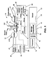
- a preferred embodiment of a spectrometric device 10 including a detector 11, an emitter 12, and an analog to digital (A/D) converter 13.
- the detector 11 may be also referred to herein as the detector cell and preferably is included in a circuit that is powered and monitored so that the voltage of the circuit that is effected by the detector 11 corresponds with the optical activity of the sample.
- the spectrometric device 10 includes computing components, which may comprise a processor 14 and storage component 15.
- a memory 16, such as a random access memory, and/or an integrated memory may be provided in association with the other computing components.
- the computing components may be associated with a board 18 that may serve to provide the electrical connections by which the computing components communicate, and which also may connect the processor 14 and/or other computing components with the other components of the device 10, such as, for example, components that may be used to supply power to or control the emitter 12 and detector 11.
- the emitter 12 preferably is provided to emit light of the spectral wavelength associated with the component (the analyte) to be analyzed, and preferably emits the wavelength ( ⁇ ) of which maximum absorbance ( ⁇ max ) is observed for the analyte.
- the spectrometric device 10 is configured as a coagulometer and is provided with an LED emitter that outputs a suitable wavelength for the detection of an analyte that is associated with blood coagulation, such as, for example, fibrin.
- the LED emitter 12 is configured to emit a wavelength of 660 nm.
- the emitter 12 preferably is configured in a power circuit that is constructed so that the emitter 12 may be regulated to change the intensity of the LED.
- the LED emitter 12 preferably may be supplied with voltage that may be intermittently cycled to provide an LED emission that is less than the percentage of continuous, constant LED light.
- the circuitry that powers the LED emitter 12 may include a clock to accomplish this.
- the detector 11 is a resistive element, which preferably comprises a photovoltaic cell that provides a voltage signal output based on the amount of light that it receives. According to a preferred embodiment, the resistance of the photocell detector 11 decreases as the amount of light it receives increases.
- the detector 11 receives from the emitter 12, the more current or voltage that is allowed to flow through the detector cell 11.
- the detector output preferably is passed through an analog to digital converter 13, so that the digital signal may be communicated to a component for further processing or reporting, such as, for example, the processor 14. This may be done with a controller 20 that is configured to capture the signal from the detector 11 and/or the detector associated A/D converter 13.
- a signal sampling rate is assigned so that the computing components, such as, for example, the processor 14, storage component 15 and memory 16, directly or through the controller 20 to which the detector 11 output is provided, may obtain and preferably store signals corresponding with the optical activity of the sample at a particular time interval, such as a number N samples per rate of time, such as seconds.
- the spectrometric device 10 is configured with settings that may be selectively programmed by the user, such as, for example, one-hundred samples of the photocell output signal per second are recorded.
- the recorded output values of the detector signal preferably are stored on a storage means such as the storage component 15.
- the storage component 15 may comprise a hard drive, magnetic or optical media, or other suitable storage medium. According to a preferred embodiment, the storage component 15 is provided as part of the spectrometric device 10.
- the spectrometric device 10 may have one or more ports 19 for accepting storage cards, such as, for example, SD, USB, and other types of flash drives or hard disk drives.
- the spectrometric device 10 may include a network interface card 21 or other suitable communication components that permit the spectrometric device 10 to communicate information, such as, for example, the output from the photocell detector 11, to another device, including a remote computer, terminal or portable communication device.
- spectrometric device 10 This may be done through wired or wireless network components that are associated with the data processing components of the device 10 that process and store the sample information, such as, for example, the processor 14, storage component 15 and memory 16.
- Some other examples of devices to which the spectrometric device 10 may communicate information include portable or non-portable computer systems, personal digital assistants (PDAs), mobile telephones, audio/visual (A/V) devices, printers, scanners, routers, switches, gateways, firewalls, and bridges.
- PDAs personal digital assistants
- A/V audio/visual
- printers printers
- scanners scanners
- routers routers
- switches gateways, firewalls, and bridges.
- the communication of the information from the spectrometric device 10 may be done through components or interfaces that are employed in connection with the communication of the signal from the detector 11.
- the processor 14 preferably may be provided with instructions to implement a determination of a value useful for determining a course of treatment for a patient.
- the instructions may be provided in the form of software or other removable or embedded logic, and may be stored, for example, on the storage component 15.
- the spectrometric device 10 may be used to obtain the output from the detector 11 over a period of time for a clotting reaction where a sample of human blood is reacted with a clotting reagent so that the fibrin that is produced by the transformation of the fibrinogen in the sample that is reacted with the clotting reagent may be measured as the analyte.
- the sampling of the detector 11 output over the course of the time of the reaction of the blood sample 101 with the clotting reagent provides optical activity values that correspond with the formation of fibrin.
- the LED wavelength emitted by the emitter 12 is a wavelength that the sample analyte, here, for example, the fibrin that is produced, absorbs, and more preferably, which is the wavelength of maximum absorbance for this analyte.
- An example of a clotting curve is illustrated in Fig. 3 , wherein optical activity values are plotted against time for a reaction involving a sample containing fibrinogen to which a reagent is added that initiates a reaction to transform the fibrinogen to fibrin.
- the absorbance of the emitted light by the sample 101 corresponds with the optical activity values.
- the spectrometric device 10 may be configured to manipulate the output of the photo detector 11 to a level that corresponds with a range of current or voltage that comprises a broad range to correspond with the range of data that is useful for determinations that are made from the photocell detector 11 output.
- the manipulation of the output of the photo detector 11 may be accomplished by regulating the LED photons that are emitted by the emitter 12.
- the output signal of the detector 11 preferably is a voltage that is measured by taking into account the resistance of the photocell detector 11.
- the device 10 includes a controller 20.
- the controller 20 handles the signals that are supplied to and received from the device components, such as, for example the emitter 12 and detector 11.
- the controller 20 preferably may be a 32-bit controller that permits assignment of a number of intensity levels for the LED emitter 12.
- the range of the intensity levels that the LED emitter 12 may emit affects the current or voltage that the detector cell 11 allows to pass through based on the resistive properties of the detector 11.
- the controller 20 provides up to 1024 potential data points for the range or scale of values that the output of the detector 11 may distinguish. The range therefore may be maximized by regulating the LED emitter 12 so that the detectible range is within the potential data point range parameters.
- the controller 20 is linked for communication with the processor 14 and other computing components, and the emitter 12 and/or the means used to supply power to the emitter 12.
- a system board 18 may be provided to link the controller 20 with the other computing components, such as the processor 14, storage component 15, memory 16 and the circuitry that operates the emitter 12 and detector 11.
- the controller 20 may be provided on or connected to the board 18.
- a screen 17 preferably is provided to display information about the components and the sample being analyzed, and preferably an input mechanism, such as for example a keypad 22, mouse, touch screen keyboard, is provided to an operator may input information and/or operate the device 10.
- the LED emitter 12 is adjusted to be set to provide an intensity that may maximize the sampling range of values so that they are spread out over the range of the bits of data that the detector 11 has available to it.
- the LED emitter 12 outputs light L 1 which passes through a sample tube, such as the cuvette 100, and is received by detection means which preferably includes a detector 11.
- the detector 11, for example, may be a silicon or selenium generating photocell (or other suitable photovoltaic cell).
- a first power source 40 is provided to power the LED emitter 12 and, in the exemplary embodiment of the device 10, comprises the means used to supply power to the emitter 12.
- the first power source 40 may be a battery 43 or may be electrical supply current that is transformed to a voltage that is desired for a range of voltages operable with the emitter 12.
- a battery 41 may serve as the first power source 40 for the LED emitter 12 and may supply direct current (DC) voltage to a regulator means that regulates the voltage applied to the LED emitter 12.
- the regulator means may comprise a voltage regulating circuit or may comprise a clock that provides power to the LED over a particular frequency.
- the regulator means is configured in conjunction with one or more of the computing components to provide computer regulated or computer assisted regulation of the LED supply voltage.
- a first converter that comprises a digital to analog (D/A) converter 35 is provided along with the first power source or emitter supply 40 and is associated therewith.
- the first D/A converter 35 preferably is configured having a variable range of voltages and is regulatable to operate over a range of voltages.
- the first D/A converter 35 may be set to a desired range of voltages (e.g., from -2.5 to 2.0 volts, or from 0 to 5 volts).
- the computing and regulating functions of the emitter 12 and detector 11 may be carried out with the spectrometric device 10.
- the computing components are in communication with the first D/A converter 35 to regulate the voltage that the emitter 12 receives.
- a computer initiated routine may be provided and implemented by the computing components of the device 10.
- the routine may be provided as computer code in software that instructs the computing components to regulate the emitter supply voltage to provide a desired range, based on the output of the response of the detector 11, which is obtained and compared during the routine.
- the regulation also may take into account the sample container 100, the sample contents including the analyte being detected in order to regulate the detector 11 output to produce signals within a desired range.
- the routine may be configured in software which may implement programs or steps to ascertain the emitter voltage supplied and the detector voltage indicated in response thereto, and further to control the voltage supply and detection voltage range to optimize the device 10 for observing a reaction, such as, in particular, the coagulation studies carried out to determine clotting activity of a blood or blood component sample.
- An example of a routine that instructs the computing components to set the voltage or voltage range associated with the emitter 12 and/or the emitter light output is set forth below, and sets out a preferred example of source code for the optimization and control of the emitter LED 12 and detector 11.
- a second power source 42 is arranged in a circuit with the photovoltaic cell detector 11.
- the second power source 42 preferably may be a battery 43 or may be electrical supply current that is transformed to a voltage that is desired for a range of voltages operable with the detector 11, including when those voltages are regulated to optimize the LED emitter 12.
- the second power source 42 preferably is configured to provide a range of voltages that power the detection cell circuit.
- the second power source 42 is connected with the second D/A converter 44.
- the detector 11 preferably has a positive lead or positive terminal 45 and a negative lead or negative terminal 46. Preferably, as illustrated in Fig. 1 , like poles of the second D/A converter 44 and power source 42 are connected.
- the positive pole 47 of the second D/A converter 44 is connected to the positive pole of the second power source 42.
- the negative pole 46 of the photovoltaic cell detector 11 is connected to the power source 42 via the negative pole 48 of the second D/A converter 44, which, as illustrated, is arranged in the circuit with a detector associated A/D converter 13 where the negative pole 48 of the second D/A converter 44 associated with the second power source 42 is fed to the detector associated A/D converter 13.
- the negative pole 46 of the photovoltaic cell detector 11 is fed to the detector associated A/D converter 13.
- FIG. 1 illustrates a schematic diagram showing a preferred arrangement for the spectrometric device 10 where the emitter 12 and detector 11 are controllable through separately operable D/A converters including a first D/A converter 35 associated with the emitter 12 and a second D/A converter 44 associated with the detector 11.
- An A/D converter 13 is provided as part of the detector circuit, and preferably, the controller 20 is connected to the first D/A converter 35 and second D/A converter 44, and preferably also the A/D converter 13. Alternately, separately provides controllers may be used and assigned to the different components.
- the computing components receive the output from the detector 11 through the detector associated A/D converter 13.
- the computing components may be provided with a target voltage range that the detector associated A/D converter 13 supplies via the detector cell 11 output.
- the computer or computing components of the device 10 preferably contain or are communicatively linked with storage media that contains instructions, such as software, that implements routines to obtain voltage values of the emitter circuit and detector circuit, compare them, and, from the device components (e.g., emitter supply 40, emitter 12, detector 11, detector supply 42), regulate the voltage through the D/A converters 35, 44.
- the computing components with the instructions from the software compare responses from the emitter 12 and detector 11 and set voltage values to provide the desired ranges associated with the emitter 12, the detector 11 or both.
- a range of voltage values may be applied to the first D/A converter 35 to regulate the output of power by way of the first power source 40 and the powering of the LED of the emitter 12.
- the software may include instructions that instruct the processor and/or other computing components to conduct this routine by implementing a series of different voltage values to apply a different power to the emitter 12.
- the detector 11 may output a signal through the detector associated A/D converter 13 so that the computer or competing components are instructed to develop a reference based on the voltage supplied to the emitter 12 and the light received at the photovoltaic cell detector 11.
- a predetermined voltage value (or range of desired values) that are desired for the output of the detector 11 are provided, and the processor and computing components are instructed to set a voltage and voltage ranges for the emitter power source 40 and the detector power source 42.
- a procedure may be carried out to optimize the LED emitter 12 to obtain the desired signal at the detector 11 (which may be a signal within a desired voltage range for the sample analyte being spectrometrically evaluated).
- the first D/A converter 35 is adjusted to provide a corresponding emitter supply voltage from the first power source 40, the battery 41. Accordingly, the output signal at the detector 11 may be adjusted by regulating the second D/A converter 44 associated with the detector 11. In this manner, the voltage that is communicated between the detector associated A/D converter 13 and the computing components receiving the signal such as the processor 14, storage component 15 or memory 16, may be set to be within a range of desired voltages.
- the emitter 12 is powered to regulate its output L 1 , and the detector cell circuit is operated by supplying power and regulating the power passing through the detector cell circuit.
- the computing components e.g., the processor 14
- the computing components are controlled with software that operates the computing components to control the emitter output and the detector cell voltage in a manner to optimize analyte detection.
- the source code preferably is provided in the form of software stored on the storage media, such as, for example, the storage component 15.
- the optimization of the LED emitter 12 may be accomplished through the following routine that may be implemented by software in conjunction with the associated components of the device 10, including the processor 14 and memory 16.
- the source code and routine below include reference to a DAQ card that may function as a controller 20 to handle the A/D conversions.
- the card is an Advantech PCI multifunction card with A/D and D/A configuration options.
- the above routines may be implemented in whole or part to provide optimization of the LED emitter 12. Alternatively, other optimization routines may be implemented to regulate the LED emitter 12 and the detection cell voltage.
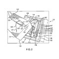
- a spectrometric device 110 including an emitter 112 and a detector 111.
- the device 110 may be operated and controlled similar to the device 10 shown and described herein.
- the spectrometric device 110 is illustrated with a sample holding mechanism and reagent delivery mechanism.
- a device housing 120 is provided to hold the components of the device 110, and, preferably, may include an upper or first housing part 121 and a lower or second housing part 122 that may be arranged together to form the housing 120.
- the housing parts 121, 122 may be removably detachable to provide access to the components enclosed therein.
- a reagent holding mechanism 125 is shown with a holder 123 for holding the reagent arm 124 provided on the upper housing part 121.
- the housing 120 may be constructed from aluminum, plastic, including molded plastic, stainless steel, or other suitable compositions, and, preferably, may be insulated to retain the temperature of the sample or samples placed therein.
- the emitter 112 is shown positioned on one side of the sample slot 200 and the detector 111 is provided with a photovoltaic detector cell positioned opposite of the emitter 112 on the other side of the sample slot 200.
- a heating block 150 is provided and contains a heating mechanism to provide a temperature controlled environment for the sample 101 (and other samples that may be held in the block 150).
- the sample slot 200 is formed in the heating block 150.
- a plurality of holding ports 200' for holding sample cuvettes is provided in the heating block 150. Accordingly, a sample cuvette, such as that 100 shown in Fig.
- sample cuvette 1 may be placed in the sample slot 200 or in one of the holding ports 200' in order to reach or maintain a desired temperature for testing.
- a number of sample cuvettes may be held in the block 150 until they are to be spectrometrically read (and, in the case of the coagulation study, until they are to be spectrometrically read and reacted with a thromboplastin or clotting agent added thereto).
- the regent holding mechanism 125 is also shown with the reagent arm 124 seated in the holder 123 attached to the upper housing 121.
- the wires 127, 128 wrapped by the shrink tubing 130 are for a heater and sensor combination which, although not shown, are disposed in the reagent arm sleeve 131.
- the sleeve 131 may comprise a copper tube or other suitable insulating component.
- a reagent heating mechanism includes the heater in the sleeve 131 and controls the temperature of the reagent prior to injection into a sample container 100.
- the reagent may be preheated at its source or at a location prior to the reagent passage through the reagent arm sleeve 131.
- the reagent holding mechanism 125 holds the reagent at a desired temperature so that it is available for dispensing into a cuvette 100 containing a sample to be evaluated.
- the reagent holding mechanism 125 preferably includes a supply line 142 through which reagent may be delivered and from which the reagent may be dispensed.
- a reagent source such as, for example a reservoir (not shown) may be provided in communication with the reagent supply line 142 so that the reagent supply line 142 may pass the reagent through to the sample holder, such as a cuvette 101.
- the reagent holding mechanism 125 may be sized to accommodate the amount of reagent that is required for a particular sample run (e.g., a single sample versus a number of samples), and the dimensions and size of the supply line 142 and reservoir (not shown) may be constructed to have suitable size dimensions for the amount of reagent that is required.
- the reagent holder heating mechanism preferably is configured so that the supply line 142 passes through the sleeve 131.
- the sleeve 131 is provided proximal to the dispensing end 143 of the supply line 142.
- the sleeve 131 may be constructed from a material that suitably maintains the temperature of the reagent, and allows the heating mechanism, such as, for example, copper.
- the heating element (not shown) and a sensor (not shown) preferably are provided within the sleeve 131 to maintain the temperature of the reagent present in the supply line 142, or that passes through the portion of the supply line 142 disposed within the sleeve 131.
- the sleeve 131 may be extended to cover additional portions or lengths of the supply line 142.
- the heating element (not shown) may be operated with a power supply fed through the wires 127, 128. Wires 127, 128 also may transmit the signal from the sleeve sensor (not shown) to an analog to digital A/D converter to provide a temperature reading.
- the reagent holder heating mechanism may include an associated A/D converter (not shown) and communicate its output to the computer component or computer.
- the A/D converter associated with the reagent arm temperature sensor is linked with the computer or the computing component of the device 110 to transmit the sensor output so the computer or computing components which preferably include software with instructions, may read and store the information in accordance with the instructions of the software implemented by the computer or computing components.
- software may be provided that is configured with instructions for recording the temperature readings of the sensor and for controlling the heater to maintain a desired reagent temperature with the sleeve 131 for delivery to a sample.
- a pump may be provided to supply reagent through the reagent supply line 142 and administer injection of the reagent into the sample container 100.
- the pump may include circuitry that is operable through software, and the computer or the computing components may manage the operation of the pump to control the injection of reagent, which may include controlling one or more of the volume of reagent, the time of injection of the reagent, and the temperature of the reagent.
- the heating block 150 is configured with a main sample slot 200 and a number of additional sample slots or holding ports 200'.
- the sample slot 200 is within the optical path, with the LED emitter 112 shown on the left and the photo cell detector 111 shown on the right.
- the detector A/D values are read from the controller 129 or data acquisition card (e.g., an Advantech multifunction DAQ PCI card).
- the arrangement of the detector circuit and the emitter circuit in the device 110 may be configured similar to the circuits shown and described in connection with the device 10 of Fig. 1 .
- the card or controller 129 preferably monitors and with the other computing components, such as, for example, those shown and described in connection with the device 10 of Fig.
- Wires 134, 135 enter the back of the aluminum heating block 150 and attach to header/sensor combination for the heating block 150 similar to the components discussed and shown in connection with the reagent arm 124 and the wires 127, 128 that are shown for the reagent arm heater and sensor housed in the arm sleeve 131.
- the initial settings of the heater associated with the reagent heating arm 124 that is in the sleeve 131 and the heater of the heating block 150 preferably are done manually and may be done using a calibrated thermometer and a small tool, such as a screwdriver.
- a temperature control unit or computer implemented control may be used to control and operate the heating and temperature sensing functions of the heating block 150 and of the reagent heating mechanism of the heating arm 124 and sleeve 131.
- the heating block 150 and arm 124 may have independent heating controls.
- the heating mechanism of the arm 124 and heating block 150 may be preset to a desired temperature for a coagulation study reaction involving fibrinogen, or the device 110 may include an option for selecting the coagulation study where the heating temperatures may be preset to a desired temperature or temperature parameters for a clotting reaction.
- the sample heating mechanism such as, for example, the heating block 150
- the heating block 150 is designed to impart heating of the sample contents 101 in order to raise the sample temperature and, preferably, to maintain the sample temperature at a desired level, or, where a preheated sample is involved, to continue to maintain the sample temperature.
- the heating block 150 is constructed from a material that may be elevated to a desired temperature and which preferably is able to maintain the desired temperature.
- One preferred material for the construction of the heating block 150 is aluminum.
- the heating block 150 preferably is connected to a supply for powering the heating block 150 heater mechanism, and is provided with a temperature sensor (not shown) whose output is transmitted through an A/D converter (e.g., through the wire leads 139).
- the heating block A/D converter preferably communicates the output to the computing components (such as those including the processor 14, storage component 15 and memory 16 described in connection with the device 10), and the signal values corresponding with the heating block 150 temperatures may be stored or reported, including being made instantaneously available for reading or viewing on a screen or monitor 149 which may be provided on or in connection with the device 110.
- the screen 149 is shown on the right side of the device 110 in Fig. 2 , the screen 149 may be provided on another location of the device 110.
- the device 110 may be configured to include some of all of the components described in connection with the device 10 of Fig. 1 , such as, for example, the input mechanism, board, network interface, storage component, memory, and processor.
- the computing components preferably are provided with software that is stored on a storage component of the device 110 and implements monitoring of the heater block temperatures and includes instructions for operating and controlling the heating mechanism of the heating block 150 in order to maintain a constant or desired sample temperature.
- the spectrometric device 110 may be used to carry out evaluations and analyses of reactions taking place in the sample container 100.
- a preferred operation of the spectrometric devices 10, 110 according to the invention is described in connection with the exemplary diagram of the device 10 shown in Fig. 1 and the exemplary embodiment shown and described in relating to Fig. 2 .
- the spectrometric device 10 is designed to supply current to the emitter 12 and to the detector 11, which may be accomplished with two separate circuits.
- the 1023 steps in the preferred embodiment illustrated herein provide for a range of 1023 steps.
- the voltage range of the A/D and D/A converters may be made variable by a computer initialization routine. For an example: (0 to 5 volts) or (-2.5 to + 2.5) volts may be set.
- the computer or computing components are operated with software that contains instructions for optimizing the LED emitter output through implementation of a routine that may evaluate the LED light output and detector 11 response at various step levels. Once a step level is associated with conforming to an optimized LED output, then steps around that level may be evaluated to fine tune the optimization of the LED output.
- the computer or computing components when a sample 100 is placed in the detection path (e.g., between the emitter 12 or 112 and the detector 11 or 111) the computer or computing components are programmed to store the converter A/D data from the detector circuit that corresponds with the output of the detector 11, 111.
- the emitter 12, 112 produces a wavelength to which the analyte being measured responds (e.g., through absorbance) and some light is passed through the sample and sample container to the detector 11, 111.
- the detector data derived from the detector response e.g., a signal
- the concentration of the analyte in the sample 101 at the time of measurement corresponds with the concentration of the analyte in the sample 101 at the time of measurement.
- the data obtained by the device components is stored in an array for processing.
- the data may be obtained and stored to represent a data point at a particular time interval (e.g., 1/100th of a second).
- the processes may be configured to display the curve and compute various points on the curve to determine results, as shown by the clotting curve represented in Fig. 3 , which shows a spike in the optical activity upon the reagent addition and follows the transformation reaction over time, until the reaction subsides.
- the data preferably is obtained by the detector 11 and its corresponding signal output which the computing components in connection with the detector circuitry may monitor and store.
- the detector 11 preferably includes a photovoltaic cell and a second power source 42 that powers the detector circuit.
- the second power source 42 preferably may comprise a constant voltage DC source, and is provided in a circuit with the photovoltaic cell 11 a of the detector 11.
- the voltage of the constant voltage DC source is changed as a result of the resistance of the photocell detector 11 based on the light L 2 (see Fig. 1 ) received by the photocell detector 11.
- a reference voltage or reading is obtained based on the photocell detector reaction to the emitter 12 providing light when no sample is contained in the light path.
- the reference voltage may be obtained by leaving the sample path clear of a sample and a sample holder, or, alternately, may be obtained by placing the sample holder in the path empty or with water (or other solvent).
- the solvent that the sample analyte is contained in may be used to obtain the reference voltage. Because other processes may reduce the intensity of the light that passes through the cuvette, in some cases, a background reading is taken for the solvent and the cuvette or sample holder.
- the voltage output that the detector 11 provides based on the LED emitter light that the detector 11 receives preferably is passed through the A/D converter 13, and a digital voltage value is provided that corresponds with an amount of light passing through the sample, and bears a relationship to the component or analyte in the sample based on the light absorbed by the analyte.
- the voltage values from the detector 11 may be processed with the computing components, such as, for example, the processor 14, storage component 15 and memory 16 of the device 10, and software that is configured with instructions to implement the functions of the processes.
- the device 10 may be programmed to relate the voltage values to absorbance based on the relative values of the voltage values obtained and measured with the detector cell 11a and A/D converter 13 of the detector circuit.
- V zero represents the value of the voltage when the light of the emitter 12 reaches the detector 11 with no sample holder or solvent in the light path.
- the denominator is adjusted by subtracting from the value V zero the value of the voltage with the sample holder and solvent in the light path so that the denominator of expression (III) above, is ( V solvent+ sample holder - V zero )
- the spectrometric device 10 may be configured with a reagent delivery system, including, for example, a reagent holding arm 131, as shown in Fig. 2 in connection with the device 110.
- a reagent delivery system including, for example, a reagent holding arm 131, as shown in Fig. 2 in connection with the device 110.
- One or more temperature control mechanisms may be provided to maintain the reagent at a desired temperature, including those discussed herein.
- the sample may be held in a sample holder that includes a heating mechanism to facilitate maintenance of the sample at a desired temperature (see e.g., the heating block 150 of Fig. 2 ).
- the detector cell 11 is positioned adjacent an opposite wall of the sample container 100, and the emitter light source 12 positioned adjacent an opposite wall, so the light L 1 emitted from the emitter light source 12 passes through the container 100.
- the emitter light source 12 is preferably configured to produce light L 1 which can be absorbed by one or more components in the sample 101 which are to be measured, or one or more components that may be generated in the sample as a result of a reaction taking place.
- the devices 10, 110 may be used to detect a single component that has maximum absorbance at a particular wavelength.
- the spectrometric devices 10, 110 may be used to carry out coagulation studies, including those discussed in my US patent nos. 6,706,536 and 7,276,377 which involve, inter alia, determinations of anticoagulant therapy factors for patients with blood disorders.
- my prior patent 5,502,651 where a potentiophotometer is used to determine optical density values for a sample containing fibrinogen, and the values of the sample when the fibrinogen undergoes a transformation to fibrin, upon a reagent addition to the sample.
- Devices 10, 110 according to the present invention may be used to define the range of detection for an analyte determination in a way that broadens the range to increase the sensitivity and the detection of changes.
- the device is configured as a blood coagulant determination device, with the computing components being programmed to regulate the emitter 12 output, the detector 11 circuit, and store and process the stored information to derive an anticoagulant therapy factor for a blood sample.
- the emitter 12 may include one or more a light emitting diodes (LEDs) emitting a predetermined wavelength, such as for example, a wavelength of 660 nm, and the detector cell 11 may, for example, comprise a silicon photovoltaic cell detector.
- a bar code reader may also be provided to read bar code labels placed on the sample container 100 (at a location that does not interfere with the light path of the emitter 12, 112).
- the bar code reader may produce a readable, unique signal or code which can be read by the computer or computing components to associate a set of data with a particular sample container 100.
- the bar code reader may be connected to the board 18 or a controller, such as for example, the controller 20.
- the spectrometric device 10 may be configured with software which preferably is stored on a storage component 15 of the device 10, such as, for example, storage media, (e.g., a hard drive).
- the device 10 may be configured to obtain coagulation analysis information, and the information obtained may then be used to determine the treatment that is needed for an individual (such as, for example, blood thinners or the like).
- the sample 101 preferably, for this example, is a blood sample or blood component sample.
- the device 10 is operated by taking readings of the optical activity of the sample 101 before, during and after a clotting reagent is added to the blood or blood component sample 101.
- the reagent is a clotting reagent that will cause the fibrinogen transformation to fibrin, so that fibrinogen in the sample will undergo a transformation to fibrin.
- the emitter 11 is preferably configured to produce an optical wavelength that corresponds with the maximum wavelength ⁇ max for the fibrin, which is about 660 nm.
- the emitter 11 produces the wavelength, and preferably, is adjusted through the operation of an optimization routine, such as the optimization routines, discussed herein, to optimize the emitter 12 output and detector 11.
- the device 10 preferably is instructed to operate the emitter 12 to emit the optimized output at the desired wavelength, which may be accomplished with software provided on the device 10, 110.
- the device 10 also preferably may include a reagent injection element, such as, for example, the reagent arm 124 that maintains the reagent at the desired temperature for addition to the sample 101.
- the device 10 though not shown, also may include a manual reagent arm 124 that draws reagent from a reservoir (not shown) that is maintained at a desired temperature.
- the reservoir may have a line 142 coming from it that delivers the reagent to the dispensing tip 143.
- a pump or other device may be used to deposit the reagent amount into the sample.
- the pump may be configured with a timer to operate for a predetermined amount of time to correspond with the delivery of the reagent amount desired to be injected or otherwise delivered to the sample 101.
- the pump may be controlled by a computer, such as the computing components of the device 10, and may correspond with the detector readings, such as, for example, timing an addition of reagent to the sample to take place after one or more initial readings of the detector signal output has been recorded, and recording the time of the addition of the reagent.
- the software is configured to implement detection of optical activity by having the detector signal read every n number of times per unit of time, such as a number of times per second.
- the optical activity corresponding to the sample in this case, the formation of fibrin from the fibrinogen in the sample 101 as a result of the reagent addition to the sample 101 is recorded and the time interval is recorded so that there is an array of data that includes optical activity values at corresponding time values.
- the plot of optical activity against time results in the clotting curve similar to that illustrated in Fig. 3 .
- the data is stored on the storage component 15, and the data is used so that an algorithm may be applied to manipulate the data using the processor 14 of the device 10 to provide a resultant coagulation value, which, preferably may be an International Normalized Ratio (INR) for a sample 101 such as a blood sample or blood component sample.
- INR International Normalized Ratio
- the determination of an INR value may enable treatment to be administered to an individual since it provides a measure corresponding with the individual's clotting activity, based on the sample evaluated with the coagulation reaction and the optical activity detected.
- the device 10 may be configured to implement reporting of the clotting activity data.
- the device 10 is configured to identify a sample, by operator input, or by a bar code assigned to or associated with the sample 101, or other unique identification mechanism.
- the sample identification and the corresponding data for the sample are stored as a sample record.
- the INR for the sample record may be reported.
- the data from which the INR is determined also may be reported as desired, in the event that it is desirable or necessary to view or access it.
- the present device 10 enables a number of samples to be processed and have their optical activity determined for a clotting reaction, and the information corresponding to each sample's clotting activity may be generated in a report form (including with such information as, sample ID, date/time that the sample was taken and INR), date of the test. Additional parameters that the report may include may be any of those observed, set or processed, such as, device settings (voltages of the emitter 12, detector 11, as well as the name of clotting reagent used, its manufacturer, international sensitivity index (ISI) and batch number).
- the device 10 preferably may include software that is programmed to implement a comparison routine that correlates different reagents to conform to a single reagent parameter.
- the thromboplastin reagent Thromboplastin C (from a particular manufacturer) may be set to be the standard, and the device 10 may be provided with software that is configured to relate the other clotting reagents, such as, for example other thromboplastins (from other manufacturers), Innovin, BPT or other clotting reagents.
- An algorithm may be stored in the software and implemented to process data.
- the device 10 preferably includes an input means, such as, for example, a keyboard or key panel, and may include a mouse or other selection device, that permits a user to enter information corresponding with a reagent, such as the reagent name, manufacturer, date, and international sensitivity index (ISI) for that reagent (which is a value that the manufacturer assigns to that lot of reagent).
- a reagent such as the reagent name, manufacturer, date, and international sensitivity index (ISI) for that reagent (which is a value that the manufacturer assigns to that lot of reagent).
- ISI international sensitivity index
- the correlation algorithm preferably relates the coagulation data, such as, for example, the INR for the sample, to correspond with a single reagent, such as, for example Thromboplastin C (TPC), even where other clotting reagents may be used to carry out the optical value coagulation study with the device 10.
- TPC Thromboplastin C
- the program may be configured to determine the TEOT with a theoretical or hypothetical zero order kinetic line, or line L, as it is referred to that appears on the Fig. 3 , which provides an (x,y) coordinate of (TEOT, 0).
- the slope of the line L may be determined based on a slope or line taken between the point where the maximum acceleration of the conversion rate of fibrinogen transformation begins (shown as T2S in Fig. 3 ) and the point marking the end of the maximum conversion rate (which is the last highest delta value of conversion rate), which is T2 or Tmap in Fig. 3 .
- the value, TEOT is a time value, and, generally, for example, may be expressed in seconds.
- the devices 10, 110 may be programmed to determine T1 and TEOT, including the commencement of the maximum conversion rate, and the last conversion rate value.
- the slope of maximum acceleration on the clotting curve that corresponds with the maximum rate of formation of fibrin during the reaction of the fibrinogen in the sample with a clotting agent is determined.
- One preferred method for determining the slope is by determining the maximum acceleration point (identified as T2 or Tmap on Fig. 3 ).
- the determination of Tmap may be done by instructing the processor 14 to sample and record optical activity values (e.g., such as absorbance values and their corresponding time values) of the sample and clotting agent as the clotting reaction takes place, and from this data, using the detector responses corresponding thereto (i.e., the optical activity values), having the processor 14 determine the last highest delta of an increasing rate of fibrinogen transformation.
- the devices 10, 110 shown and described herein may be used to carry out coagulation studies for a plurality of patient records, store and communicate data to an operator of the device 10, 110, or to an alternate or remote location.
- the means to supply power is illustrated as a separately provided first power source 40 and a second power source 42, according to alternate embodiments, power may be supplied through the computing components, and may be regulated with D/A converters as described to control the voltage.
- the device is configured to interface or connect with a computer.
- Software preferably is provided and is installed on the computer so that the computer may communicate with the device and control the operations of the device, as discussed herein.
- the device is configured with an interface, such as a port or card, that connects with a port of the computer (e.g., serial port, USB port, or other suitable port connection).
- the device preferably has its own power supply for supplying power to the components of the device, and the computer, configured with software, may be operated to control the emitter output, detector response, sampling times, heating block temperature and other components of the device.
- the software instructs the computer to carry out monitoring functions and collects and stores data, and manipulates the data in accordance with expressions that are used to carry out a coagulation study, such as, for example, a study of a patient blood sample that undergoes a reaction with a clotting reagent (e.g., thromboplastin) to determine clotting activity based on the transformation of fibrinogen in the sample to fibrin.
- a coagulation study such as, for example, a study of a patient blood sample that undergoes a reaction with a clotting reagent (e.g., thromboplastin) to determine clotting activity based on the transformation of fibrinogen in the sample to fibrin.
- a coagulation study such as, for example, a study of a patient blood sample that undergoes a reaction with a clotting reagent (e.g., thromboplastin) to determine clotting activity based on the transformation of fibrinogen in the sample to fibrin.
- the processor 14 and storage component 15 may be provided in the form of a computer (such as, for example an IBM compatible computer, or other type of computer), and linked for communication with the detector 11 and its output, and/or other component with which the detector 11 interfaces or is associated.
- the computer (not shown) may be linked for communication with the emitter 12 and/or other component associated with or interfacing with the emitter 12.
- the uses of the devices 10 and 110 are, at times, separately referred to in connection with a description of the methods or operations thereof, the features of the devices 10, 110 may be interchanged.
- the reagent arm 125 and heating block 150 may be utilized in connection with the device 10, and, likewise, the components, including converters, power supplies, of the device 10 may be used with the device 110.
- the sample container used to contain the sample may comprise a vial, or cuvette, including, for example, the sample container disclosed in our U.S. Patent 6,706,536 .
- the spectrometric device 10, 110 although described as having use in connection with body fluids of a human, may be used in connection with veterinary procedures, as well, where fluids are to be measured or analyzed.
- veterinary procedures as well, where fluids are to be measured or analyzed.
Landscapes
- Physics & Mathematics (AREA)
- Health & Medical Sciences (AREA)
- Life Sciences & Earth Sciences (AREA)
- Chemical & Material Sciences (AREA)
- Engineering & Computer Science (AREA)
- Spectroscopy & Molecular Physics (AREA)
- General Physics & Mathematics (AREA)
- Biomedical Technology (AREA)
- Immunology (AREA)
- Pathology (AREA)
- General Health & Medical Sciences (AREA)
- Biochemistry (AREA)
- Analytical Chemistry (AREA)
- Hematology (AREA)
- Medicinal Chemistry (AREA)
- Food Science & Technology (AREA)
- Biophysics (AREA)
- Molecular Biology (AREA)
- Urology & Nephrology (AREA)
- Chemical Kinetics & Catalysis (AREA)
- Plasma & Fusion (AREA)
- Ecology (AREA)
- Investigating Or Analysing Materials By Optical Means (AREA)
Applications Claiming Priority (2)
| Application Number | Priority Date | Filing Date | Title |
|---|---|---|---|
| US12/932,824 US20120231534A1 (en) | 2011-03-07 | 2011-03-07 | Spectrometric device |
| EP12158423 | 2012-03-07 |
Related Parent Applications (1)
| Application Number | Title | Priority Date | Filing Date |
|---|---|---|---|
| EP12158423 Division | 2011-03-07 | 2012-03-07 |
Publications (2)
| Publication Number | Publication Date |
|---|---|
| EP2515097A2 true EP2515097A2 (fr) | 2012-10-24 |
| EP2515097A3 EP2515097A3 (fr) | 2014-05-07 |
Family
ID=46795923
Family Applications (1)
| Application Number | Title | Priority Date | Filing Date |
|---|---|---|---|
| EP12163033.9A Withdrawn EP2515097A3 (fr) | 2011-03-07 | 2012-03-07 | Dispositif spectrométrique |
Country Status (2)
| Country | Link |
|---|---|
| US (1) | US20120231534A1 (fr) |
| EP (1) | EP2515097A3 (fr) |
Cited By (2)
| Publication number | Priority date | Publication date | Assignee | Title |
|---|---|---|---|---|
| CN102944304A (zh) * | 2012-10-17 | 2013-02-27 | 杭州师范大学 | 一种水面上光谱测量的多角度观测支架 |
| EP3699575A4 (fr) * | 2017-09-13 | 2021-12-01 | Giparang Co., Ltd. | Capteur ayant une capacité de détection améliorée |
Families Citing this family (3)
| Publication number | Priority date | Publication date | Assignee | Title |
|---|---|---|---|---|
| US10139263B2 (en) * | 2013-03-11 | 2018-11-27 | Honeywell International Inc. | Method to calibrate disposable cartridge cuvette thickness in-situ |
| CN104483283A (zh) * | 2014-12-29 | 2015-04-01 | 山西鑫华翔科技发展有限公司 | 非色散分光光度测量电路 |
| CN118162377B (zh) * | 2024-04-03 | 2025-05-02 | 揭阳市万佳晟环保科技有限公司 | 建筑废料分离系统 |
Citations (7)
| Publication number | Priority date | Publication date | Assignee | Title |
|---|---|---|---|---|
| US5106190A (en) | 1988-09-24 | 1992-04-21 | Shimadzu Corporation | Double-beam spectrophotometer using a photodiode detector |
| US5257086A (en) | 1992-06-09 | 1993-10-26 | D.O.M. Associates Int'l | Optical spectrophotometer having a multi-element light source |
| US5488474A (en) | 1994-05-06 | 1996-01-30 | D.O.M. Associates Int'l. | Hadamard phasing in a multisource array |
| US5502651A (en) | 1994-05-02 | 1996-03-26 | Jackson; R. David | Potentiophotometric fibrinogen determination |
| US6706536B1 (en) | 2000-11-28 | 2004-03-16 | Wada, Inc. | Method and apparatus for processing coagulation studies, chemistry procedures and the like |
| US7276377B2 (en) | 2003-05-02 | 2007-10-02 | Wada, Inc. | Method and apparatus for determining anticoagulant therapy factors |
| US7489398B2 (en) | 2003-10-29 | 2009-02-10 | Saika Technological Institute Foundation | Spectrophotometer |
Family Cites Families (10)
| Publication number | Priority date | Publication date | Assignee | Title |
|---|---|---|---|---|
| US5100805A (en) * | 1989-01-26 | 1992-03-31 | Seradyn, Inc. | Quantitative immunoassay system and method for agglutination assays |
| US5197017A (en) * | 1990-09-27 | 1993-03-23 | Carroll Wallace E | Potentiophotometric fibrinogen determination |
| FR2749076A1 (fr) * | 1996-05-21 | 1997-11-28 | Generys Technologie S A | Procede de determination de la densite optique et densitometre |
| CN1309770A (zh) * | 1998-07-31 | 2001-08-22 | 华莱士·E·卡罗尔 | 确定抗凝治疗因子的设备和方法 |
| US20030038942A1 (en) * | 2001-06-15 | 2003-02-27 | Nexpress Solutions Llc | Densitometer with improved accuracy |
| US20040219680A1 (en) * | 2003-05-02 | 2004-11-04 | Carroll Wallace E. | Method and apparatus for determining anticoagulant therapy factors |
| US7343186B2 (en) * | 2004-07-07 | 2008-03-11 | Masimo Laboratories, Inc. | Multi-wavelength physiological monitor |
| US7148628B2 (en) * | 2004-07-30 | 2006-12-12 | Desa Ip, Llc | Photosensitive control with dynamic calibration |
| US7453555B2 (en) * | 2005-05-20 | 2008-11-18 | Bio/Data Corporation | Aggregometer with near ultraviolet light source |
| US8445287B2 (en) * | 2009-02-14 | 2013-05-21 | Wada, Inc. | Method and apparatus for determining anticoagulant therapy factors |
-
2011
- 2011-03-07 US US12/932,824 patent/US20120231534A1/en not_active Abandoned
-
2012
- 2012-03-07 EP EP12163033.9A patent/EP2515097A3/fr not_active Withdrawn
Patent Citations (7)
| Publication number | Priority date | Publication date | Assignee | Title |
|---|---|---|---|---|
| US5106190A (en) | 1988-09-24 | 1992-04-21 | Shimadzu Corporation | Double-beam spectrophotometer using a photodiode detector |
| US5257086A (en) | 1992-06-09 | 1993-10-26 | D.O.M. Associates Int'l | Optical spectrophotometer having a multi-element light source |
| US5502651A (en) | 1994-05-02 | 1996-03-26 | Jackson; R. David | Potentiophotometric fibrinogen determination |
| US5488474A (en) | 1994-05-06 | 1996-01-30 | D.O.M. Associates Int'l. | Hadamard phasing in a multisource array |
| US6706536B1 (en) | 2000-11-28 | 2004-03-16 | Wada, Inc. | Method and apparatus for processing coagulation studies, chemistry procedures and the like |
| US7276377B2 (en) | 2003-05-02 | 2007-10-02 | Wada, Inc. | Method and apparatus for determining anticoagulant therapy factors |
| US7489398B2 (en) | 2003-10-29 | 2009-02-10 | Saika Technological Institute Foundation | Spectrophotometer |
Cited By (3)
| Publication number | Priority date | Publication date | Assignee | Title |
|---|---|---|---|---|
| CN102944304A (zh) * | 2012-10-17 | 2013-02-27 | 杭州师范大学 | 一种水面上光谱测量的多角度观测支架 |
| CN102944304B (zh) * | 2012-10-17 | 2014-07-02 | 杭州师范大学 | 一种水面上光谱测量的多角度观测支架 |
| EP3699575A4 (fr) * | 2017-09-13 | 2021-12-01 | Giparang Co., Ltd. | Capteur ayant une capacité de détection améliorée |
Also Published As
| Publication number | Publication date |
|---|---|
| EP2515097A3 (fr) | 2014-05-07 |
| US20120231534A1 (en) | 2012-09-13 |
Similar Documents
| Publication | Publication Date | Title |
|---|---|---|
| US7245373B2 (en) | Spectrometer system for optical reflectance measurements | |
| US5365066A (en) | Low cost means for increasing measurement sensitivity in LED/IRED near-infrared instruments | |
| US9924778B2 (en) | Systems and methods for measuring spectra of skin and other objects and materials and making predictions based thereon | |
| US4935875A (en) | Chemical analyzer | |
| EP1086366B1 (fr) | Procede de controle de la qualite d'un spectrophotometre | |
| EP1046028B1 (fr) | Fluorometre d'immunodosage | |
| EP2515097A2 (fr) | Dispositif spectrométrique | |
| US6074616A (en) | Media carrier for an assay device | |
| KR100840949B1 (ko) | 다중 채널 광학적 검출 시스템 | |
| US20080174768A1 (en) | Self referencing LED detection system for spectroscopy applications | |
| US7981662B2 (en) | Analyzer | |
| HK1055552B (zh) | 由拉曼光谱检测体液中物质的方法和设备 | |
| EP2267435A1 (fr) | Fluorimètre à cellule ouverte-extrémité interchangeable | |
| US8594758B2 (en) | Transmission fluorometer | |
| US20130248695A1 (en) | Method and apparatus for analyte detection | |
| WO2011117572A1 (fr) | Analyse de la respiration | |
| EP2584342B1 (fr) | Procédé de mesures optiques quantitatives et appareil de laboratoire | |
| JP2021514051A (ja) | 分析装置 | |
| CN112011455A (zh) | 一种用于实时荧光定量pcr仪的温场与光路双通道检测装置 | |
| US11740181B2 (en) | Preparation device, diagnostic apparatus, diagnostic kit and diagnostic system | |
| US20020190356A1 (en) | Media carrier for an assay device | |
| JP2006308420A (ja) | 水質測定器 | |
| Aziz et al. | Validation of Spectroscopy Performance and Calibration in Compliance with ISO Standards | |
| JP2005010049A (ja) | 融解温度測定装置 | |
| FI20245284A1 (en) | Calibration procedure and system |
Legal Events
| Date | Code | Title | Description |
|---|---|---|---|
| PUAI | Public reference made under article 153(3) epc to a published international application that has entered the european phase |
Free format text: ORIGINAL CODE: 0009012 |
|
| AK | Designated contracting states |
Kind code of ref document: A2 Designated state(s): AL AT BE BG CH CY CZ DE DK EE ES FI FR GB GR HR HU IE IS IT LI LT LU LV MC MK MT NL NO PL PT RO RS SE SI SK SM TR |
|
| AX | Request for extension of the european patent |
Extension state: BA ME |
|
| PUAL | Search report despatched |
Free format text: ORIGINAL CODE: 0009013 |
|
| AK | Designated contracting states |
Kind code of ref document: A3 Designated state(s): AL AT BE BG CH CY CZ DE DK EE ES FI FR GB GR HR HU IE IS IT LI LT LU LV MC MK MT NL NO PL PT RO RS SE SI SK SM TR |
|
| AX | Request for extension of the european patent |
Extension state: BA ME |
|
| RIC1 | Information provided on ipc code assigned before grant |
Ipc: G01N 33/49 20060101ALI20140401BHEP Ipc: G01N 21/25 20060101AFI20140401BHEP Ipc: G01N 21/51 20060101ALI20140401BHEP Ipc: G01N 21/82 20060101ALI20140401BHEP |
|
| STAA | Information on the status of an ep patent application or granted ep patent |
Free format text: STATUS: THE APPLICATION IS DEEMED TO BE WITHDRAWN |
|
| 18D | Application deemed to be withdrawn |
Effective date: 20141001 |