EP2515571B1 - Procédé et dispositif permettant de surveiller un canal de commande dans un système de communication sans fil - Google Patents
Procédé et dispositif permettant de surveiller un canal de commande dans un système de communication sans fil Download PDFInfo
- Publication number
- EP2515571B1 EP2515571B1 EP10837864.7A EP10837864A EP2515571B1 EP 2515571 B1 EP2515571 B1 EP 2515571B1 EP 10837864 A EP10837864 A EP 10837864A EP 2515571 B1 EP2515571 B1 EP 2515571B1
- Authority
- EP
- European Patent Office
- Prior art keywords
- control region
- extended
- pdcch
- control
- subframe
- Prior art date
- Legal status (The legal status is an assumption and is not a legal conclusion. Google has not performed a legal analysis and makes no representation as to the accuracy of the status listed.)
- Not-in-force
Links
Images





Classifications
-
- H—ELECTRICITY
- H04—ELECTRIC COMMUNICATION TECHNIQUE
- H04W—WIRELESS COMMUNICATION NETWORKS
- H04W24/00—Supervisory, monitoring or testing arrangements
-
- H—ELECTRICITY
- H04—ELECTRIC COMMUNICATION TECHNIQUE
- H04W—WIRELESS COMMUNICATION NETWORKS
- H04W48/00—Access restriction; Network selection; Access point selection
- H04W48/16—Discovering, processing access restriction or access information
Definitions
- the present invention relates to wireless communications, and more particularly, to a method and apparatus for monitoring a control channel in a wireless communication system.
- 3GPP LTE 3 rd generation partnership project (3GPP) long term evolution (LTE) evolved from a universal mobile telecommunications system (UMTS) is introduced as the 3GPP release 8.
- 3GPP LTE uses orthogonal frequency division multiple access (OFDMA) in a downlink, and uses single carrier-frequency division multiple access (SC-FDMA) in an uplink.
- OFDMA orthogonal frequency division multiple access
- SC-FDMA single carrier-frequency division multiple access
- MIMO multiple input multiple output
- LTE-A 3GPP LTE-advanced
- the 3GPP LTE system supports only one bandwidth (i.e., one component carrier) among ⁇ 1.4, 3, 5, 10, 15, 20 ⁇ MHz.
- carrier aggregation uses two carriers having a bandwidth of 20MHz or uses 3 carriers respectively having bandwidths of 20MHz, 15MHz, and 5MHz.
- One component carrier corresponds to one cell.
- the carrier aggregation can support backward compatibility with legacy systems, and can significantly increase a data rate by using a plurality of component carriers.
- a control channel and a data channel are designed on the basis of a single component carrier.
- the control channel is monitored only in a specific region of a subframe. Since a plurality of component carriers are used due to carrier aggregation, there is an increase in an amount of control information for the plurality of component carriers. Therefore, it may be not enough to transmit all control channels by using only a region for the conventional control channel.
- the 3GPP Draft No. R1-094569 entitled “PDCCH Extension to Support Operation with CI”, discloses a scheme for extending the PDCCH size so as to allow for the inclusion of a "Carrier Indicator (CI) field" in a LTE system supporting carrier aggregation.
- CI Carrier Indicator
- the present invention provides a method and apparatus for monitoring a control channel in a wireless communication system.
- a method for monitoring a control channel in a wireless communication system is provided as set forth in the appended claims.
- a user equipment configured for monitoring a control channel in a wireless communication system is provided as set forth in the appended claims.
- An additional control region can be defined to transmit a large amount of control information. Backward compatibility with a legacy system is guaranteed, and an overhead of a user equipment for detecting a control channel can be prevented from increasing.
- a user equipment may be fixed or mobile, and may be referred to as another terminology, such as a mobile station (MS), a mobile terminal (MT), a user terminal (UT), a subscriber station (SS), a wireless device, a personal digital assistant (PDA), a wireless modem, a handheld device, etc.
- MS mobile station
- MT mobile terminal
- UT user terminal
- SS subscriber station
- PDA personal digital assistant
- a base station is generally a fixed station that communicates with the UE and may be referred to as another terminology, such as an evolved node-B (eNB), a base transceiver system (BTS), an access point, etc.
- eNB evolved node-B
- BTS base transceiver system
- access point etc.
- Each BS provides a communication service to a specific geographical region (generally referred to as a cell).
- the cell can be divided into a plurality of regions (referred to as sectors).
- FIG. 1 shows a downlink radio frame structure in 3 rd generation partnership project (3GPP) long term evolution (LTE).
- 3GPP 3 rd generation partnership project
- LTE long term evolution
- a radio frame consists of 20 subframes indexed with 0 to 19.
- One subframe consists of 2 slots.
- a time required for transmitting one subframe is defined as a transmission time interval (TTI).
- TTI transmission time interval
- one subframe may have a length of 1 millisecond (ms)
- one slot may have a length of 0.5 ms.
- One slot may include a plurality of orthogonal frequency division multiplexing (OFDM) symbols in a time domain.
- OFDM orthogonal frequency division multiplexing
- the OFDM symbol is only for expressing one symbol period in the time domain, and there is no limitation in a multiple access scheme or terminologies.
- the OFDM symbol may also be referred to as another terminology such as a single carrier frequency division multiple access (SC-FDMA) symbol, a symbol period, etc.
- SC-FDMA single carrier frequency division multiple access
- one slot includes 7 OFDM symbols for example, the number of OFDM symbols included in one slot may vary depending on a length of a cyclic prefix (CP).
- CP cyclic prefix
- a resource block is a resource allocation unit, and includes a plurality of subcarriers in one slot. For example, if one slot includes 7 OFDM symbols in a time domain and the RB includes 12 subcarriers in a frequency domain, one RB can include 7x12 resource elements (REs).
- REs resource elements
- a DL subframe is divided into a control region and a data region in the time domain.
- the control region includes up to three preceding OFDM symbols of a 1 st slot in the subframe.
- the number of OFDM symbols included in the control region may vary.
- a physical downlink control channel (PDCCH) is allocated to the control region, and a physical downlink shared channel (PDSCH) is allocated to the data region.
- PDCCH physical downlink control channel
- PDSCH physical downlink shared channel
- the 3GPP LTE classifies a physical channel into a data channel and a control channel.
- the data channel include a physical downlink shared channel (PDSCH) and a physical uplink shared channel (PUSCH).
- Examples of the control channel include a physical downlink control channel (PDCCH), a physical control format indicator channel (PCFICH) and a physical hybrid-ARQ indicator channel (PHICH), and a physical uplink control channel (PUCCH).
- the PCFICH transmitted in a 1 st OFDM symbol in the subframe carries a control format indicator (CFI) regarding the number of OFDM symbols (i.e., a size of the control region) used for transmission of control channels in the subframe.
- CFI control format indicator
- the UE first receives the CFI through the PCFICH, and thereafter monitors the PDCCH.
- the PCFICH is transmitted through a fixed PCFICH resource of the subframe, without using blind decoding.
- the PHICH carries a positive acknowledgement (ACK)/negative-acknowledgement (NACK) signal for uplink hybrid automatic repeat request (HARQ).
- ACK positive acknowledgement
- NACK negative-acknowledgement
- HARQ uplink hybrid automatic repeat request
- the ACK/NACK signal for uplink (UL) data on the PUSCH transmitted by the UE is transmitted on the PHICH.
- a physical broadcast channel is transmitted in first four OFDM symbols in a 2 nd slot of a 1 st subframe of a radio frame.
- the PBCH carries system information necessary for communication between a UE and a BS.
- the system information transmitted through the PBCH is referred to as a master information block (MIB).
- MIB master information block
- SIB system information block
- the DCI may include resource allocation of the PDSCH (this is referred to as a DL grant), resource allocation of a PUSCH (this is referred to as a UL grant), a set of transmit power control commands for individual UEs in any UE group and/or activation of a voice over Internet protocol (VoIP).
- DCI downlink control information
- the DCI may include resource allocation of the PDSCH (this is referred to as a DL grant), resource allocation of a PUSCH (this is referred to as a UL grant), a set of transmit power control commands for individual UEs in any UE group and/or activation of a voice over Internet protocol (VoIP).
- VoIP voice over Internet protocol
- FIG. 2 shows a PDCCH configuration.
- a BS determines a PDCCH format according to DCI to be transmitted to a UE, attaches a cyclic redundancy check (CRC) to control information, and masks a unique identifier (referred to as a radio network temporary identifier (RNTI)) to the CRC according to an owner or usage of the PDCCH (step 110).
- CRC cyclic redundancy check
- RNTI radio network temporary identifier
- a unique identifier (e.g., cell-RNTI (C-RNTI)) of the UE may be masked to the CRC.
- C-RNTI cell-RNTI
- a paging indication identifier (e.g., paging-RNTI (P-RNTI)) may be masked to the CRC.
- P-RNTI paging-RNTI
- SI-RNTI system information-RNTI
- RA-RNTI random access-RNTI
- the PDCCH When the C-RNTI is used, the PDCCH carries control information for a specific UE (such information is called UE-specific control information), and when other RNTIs are used, the PDCCH carries common control information received by all or a plurality of UEs in a cell.
- the CRC-attached DCI is encoded to generate coded data (step 120).
- Encoding includes channel encoding and rate matching.
- the coded data is modulated to generate modulation symbols (step 130).
- the modulation symbols are mapped to physical resource elements (REs) (step 140).
- the modulation symbols are respectively mapped to the REs.
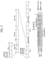
- FIG. 3 shows exemplary resource mapping of a PDCCH. Further details in this regard can be found in the section 6 of 3GPP TS 36.211 V8.7.0.
- R0 denotes a reference signal of a 1 st antenna.
- R1 denotes a reference signal of a 2 nd antenna.
- R2 denotes a reference signal of a 3 rd antenna.
- R3 denotes a reference signal of a 4 th antenna.
- a control region in a subframe includes a plurality of control channel elements (CCEs).
- the CCE is a logical allocation unit used to provide the PDCCH with a coding rate depending on a radio channel state, and corresponds to a plurality of resource element groups (REGs).
- REGs resource element groups
- One REG (indicated by a quadruplet in the drawing) includes 4 REs.
- One CCE includes 9 REGs.
- the number of CCEs used to configure one PDCCH may be selected from a set ⁇ 1, 2, 4, 8 ⁇ . Each element of the set ⁇ 1, 2, 4, 8 ⁇ is referred to as a CCE aggregation level.
- a control channel consisting of one or more CCEs performs interleaving in an REG unit, and is mapped to a physical resource after performing cyclic shift based on a cell identifier (ID).
- ID cell identifier
- the 3GPP LTE uses blind decoding for PDCCH detection.
- the blind decoding is a scheme in which a desired identifier is de-masked from a CRC of a received PDCCH (referred to as a candidate PDCCH) to determine whether the PDCCH is its own control channel by performing CRC error checking.
- a plurality of PDCCHs can be transmitted in one subframe.
- a UE monitors a plurality of PDCCHs in every sub frame. Monitoring is an operation of attempting PDCCH decoding by the UE according to a format of the monitored PDCCH.
- the 3GPP LTE uses a search space to reduce an overhead caused by blind decoding.
- the search space is classified into a common search space and a UE-specific search space.
- the common search space is a space for searching for a PDCCH having common control information and consists of 16 CCEs indexed with 0 to 15.
- the common search space supports a PDCCH having a CCE aggregation level of ⁇ 4, 8 ⁇ .
- the UE-specific search space supports a PDCCH having a CCE aggregation level of ⁇ 1, 2, 4, 8 ⁇ .
- a resource element is a minimum frequency-time unit by which a modulation symbol of a data channel or a modulation symbol of a control channel is mapped. If there are M subcarriers on one OFDM symbol and if one slot includes N OFDM symbols, then one slot includes MxN REs.
- a physical resource block is a unit frequency-time resource for transmitting data.
- One PRB consists of a plurality of REs contiguous in a frequency-time domain, and a plurality of PRBs are defined in one subframe.
- a virtual resource block is a virtual unit resource for transmission of the data channel or the control channel.
- the number of REs included in one VRB is equal to the number of REs included in one PRB.
- one VRB can be mapped to the PRB or one VRB can be mapped to a plurality of PRBs.
- a localized virtual resource block is one type of the VRB.
- One LVRB is mapped to one PRB, and there is no overlapping of PRBs to which different LVRBs are mapped.
- the LVRB can be interpreted directly as the PRB.
- a distributed virtual resource block is another type of the VRB.
- One DVRB is mapped to some REs in a plurality of PRBs, and there is no overlapping of REs which are mapped to different DVRBs.
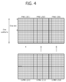
- FIG. 4 shows LVRB-PRB mapping in 3GPP LTE. Although it is shown herein that both of an LVRB and a PRB include 12 subcarriers in one slot and one slot includes 6 OFDM symbols, the number of OFDM symbols included in one slot and the number of subcarriers included therein are for exemplary purposes only.
- An LVRB1 211 is mapped to a PRB1 201.
- An LVRB2 212 is mapped to a PRB2 202.
- An LVRB3 213 is mapped to a PRB3 203.
- the LVRB is one-to-one mapped to the PRB.
- An LVRB having an index i corresponds to a PRB having an index j. According to a VRB allocation scheme, i and j may be equal to or different from each other.
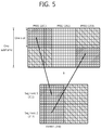
- FIG. 5 shows DVRB-PRB mapping in 3GPP LTE.
- a DVRB is divided into N D segments in a frequency domain. Each segment is mapped to a plurality of PRBs.
- N D 2.
- a DVRB1 310 is divided into a segment1 311 and a segment2 312. The two segments are respectively mapped to a PRB1 301 and a PRB3 303.
- FIG. 6 shows resource allocation in 3GPP LTE.
- FIG. 6A shows a DL resource allocation
- FIG. 6B shows a UL resource allocation.
- a UE monitors a PDCCH, and receives a DL grant through a PDCCH 501.
- the DL grant includes a VRB allocation for a PDSCH 502.
- the UE receives the DL transport block through the PDSCH 502 indicated by the DL grant.
- the UE acquires a VRB mapped to a PRB, in which the PDSCH 502 is transmitted, on the basis of the VRB allocation and thus receives the DL transport block.
- the UE monitors the PDCCH in a DL subframe and receives the UL resource allocation through a PDCCH 551.
- the DL resource allocation includes a VRB allocation for a PUSCH 552.
- the UE transmits the UL transport block through the PUSCH 552 configured based on the UL resource allocation.
- the UE maps the VRB allocated based on the VRB allocation to a PRB, and transmits the PUSCH 552 by using the mapped PRB.
- the UE can determine a PRB for receiving the DL transport block or for transmitting the UL transport block.
- the VRB allocation consists of a typical bitmap. If there are N RB VRBs, N RB bits are required for the bitmap. This may result in a problem in that a size of a payload of DCI transmitted through the PDCCH is increased in proportion to the number of VRBs.
- the VRB allocation is classified into a type 0, a type 1, and a type 2, and a resource block group (RBG) and a subset are introduced.
- RBG resource block group
- a multiple-carrier system supporting a plurality of component carriers (CCs) is taken into account.
- Spectrum aggregation supports a plurality of CCs.
- the spectrum aggregation is introduced to support an increasing throughput, to prevent a cost increase caused by using a broadband radio frequency (RF) element, and to ensure compatibility with legacy systems. For example, if 5 CCs are assigned as a granularity of a carrier unit having a bandwidth of 20MHz, a bandwidth of up to 100MHz can be supported.
- RF radio frequency
- the CC may correspond to one cell.
- a UE supporting a plurality of CCs can receive a service from a plurality of cells.
- FIG. 7 shows an example of multiple carriers. Although three DL CCs and three UL CCs are shown herein, the number of DL CCs and the number of UL CCs are not limited thereto.
- a PDCCH and a PDSCH are independently transmitted in each DL CC.
- a PUCCH and a PUSCH are independently transmitted in each UL CC.
- a CC linkage can be defined between a DL CC and a UL CC.
- the CC linkage implies a mapping relation between a DL CC in which a PDCCH for carrying a UL grant is transmitted and a UL CC scheduled by the UL grant.
- the CC linkage may be a mapping relation between a DL CC (or UL CC) in which data for HARQ is transmitted or a UL CC (or DL CC) in which an HARQ ACK/NACK signal is transmitted.
- FIG. 7 shows a symmetric CC linkage in which a DL CC and a UL CC are one-to-one mapped.
- CC scheduling When the CC linkage is defined, two methods are possible as CC scheduling.
- the CC linkage is fixed. This is called a fixed CC linkage or a static CC linkage.
- a UL grant is transmitted through the DL CC.
- a UL transport block is transmitted by using the UL grant through a UL CC linked to the DL CC. Since a UL CC to be scheduled by the UL grant can be determined through a predefined CC linkage, additional signaling is not necessary.
- the CC linkage is dynamically or semi-statically changed or overridden.
- a PDCCH and a PDSCH are transmitted in different DL CCs, or a PUSCH is transmitted through a UL CC not linked to a DL CC in which the PDCCH is transmitted. This is called cross-carrier scheduling.
- FIG. 8 shows an example of cross-carrier scheduling. It is assumed that a DL CC #1 is linked to a UL CC #1, a DL CC #2 is linked to a UL CC #2, and a DL CC #3 is linked to a UL CC #3.
- a 1 st PDCCH 710 of the DL CC #1 carries DCI for a PDSCH 702 of the same DL CC #1.
- a 2 nd PDCCH 711 of the DL CC #1 carries DCI for a PDSCH 712 of the DL CC #2.
- a 3 rd PDCCH 721 of the DL CC #1 carries DCI for a PUSCH 722 of the unlinked UL CC #3.
- the DCI of the PDCCH may include a carrier indicator field (CIF).
- the CIF indicates a DL CC or a UL CC scheduled through the DCI.
- the CIF may include an index of a UL CC or an index of a DL CC scheduled through the DCI.
- the 2 nd PDCCH 711 may include a CIF indicating the DL CC #2.
- the 3 rd PDCCH 721 may include a CIF indicating the UL CC #3.
- a CFI indicated by a CC in which the PDCCH is detected is called a self-CFI.
- a CFI indicated by a CC different from the CC in which the PDCCH is detected is called a cross-CFI.
- a CC in which the CFI is obtained (or transmitted) is equal to a CC in which the CFI is used.
- a CC in which the CFI is obtained (or transmitted) is different from a CC in which the CFI is used. That is, when the UE performs PDCCH monitoring in the DL CC #2, if the CFI is directly obtained from the DL CC #2, it is the self-CFI, and if the CFI is obtained from another CC (i.e., the CC #1 or the CC #3), it is the cross-CFI.
- FIG. 9 shows an exemplary operation of a multi-carrier system.
- a UE can know a CFI of a DL CC #1 through a PCFICH 901 of the DL CC #1. Therefore, a PDCCH can be monitored in a control region.
- the UE can receive DL data from a PDSCH 921 of the DL CC #1 through a 1 st PDCCH 911.
- a 2 nd PDCCH 912 indicates a PDSCH 922 of a DL CC #2 and a 3 rd PDCCH 913 indicates a PDSCH 923 of a DL CC #3. It is also assumed that the DL CC #2 is a CC in which its control region is allocated, whereas the DL CC #3 is a PDCCH-less CC in which its control region is not allocated.
- control channels for other CCs are scheduled in a specific CC
- the existing control channel consisting of up to 3 OFDM symbols may be insufficient.
- PDCCHs for the DL CC #2 and the DL CC #3 are transmitted through the DL CC #1, a control region of the DL CC #1 may be insufficient.
- FIG. 10 shows control information transmission according to an embodiment of the present invention.
- a subframe 1000 includes a control region 1001, a data region 1002, and an extended control region 1003.
- the extended control region 1003 is used to transmit some PDCCHs of the existing data region.
- a CFI for reporting a size of the existing control region 1001 is transmitted through a PCFICH 1010.
- Extended control information regarding the extended control region 1003 is transmitted through an E-PCFICH 1020. Since the CFI is transmitted through the PCFICH 1010, backward compatibility with the existing 3GPP LTE is guaranteed.
- the extended control information includes presence information regarding whether the extended control region 1003 is present and/or resource allocation information of the extended control region 1003.
- the extended control information may include a cross-CFI.
- the presence information regarding whether the extended control region 1003 is present is transmitted through the E-PCFICH 1020, and the extended control region 1003 can use a predetermined resource.
- the resource allocation information of the extended control region 1003 and the presence information can be transmitted through the E-PCFICH 1020.
- Whether the extended control region 1003 is present is determined according to the presence of the E-PCFICH 1020, and the resource allocation information of the extended control region 1003 can be transmitted through the E-PCFICH 1020.
- the extended control region 1003 can be allocated in an OFDM symbol unit. Alternatively, the extended control region 1003 can be allocated in an RB unit. To obtain sufficient frequency diversity, the extended control region 1003 may follow DVRB allocation of the PDSCH. Alternatively, an RB of a 1 st slot may follow the DVRB allocation, and an RB of a 2 nd slot may follow RB allocation on the same frequency as RB allocation of the 1 st slot.
- a resource predetermined in the control region 1001 can be used for transmission of the E-PCFICH 1020. Therefore, the UE can attempt to detect the E-PCFICH 1020 by searching for the determined resource.
- a fixed resource such as an RE allocated to the PHICH can be used for transmission of the E-PCFICH 1020.
- CCEs of the existing PDCCH are used for transmission of the E-PCFICH 1020, and detection of the E-PCFICH 1020 can be attempted through blind decoding.
- an extended identifier can be used in CRC masking.
- the extended identifier may be UE specific or cell specific.
- An identifier such as the existing C-RNTI can be reused as the extended identifier.
- a search space in which the E-PCFICH 1020 is searched can be limited. It can be limited to a UE-specific search space or a common search space, or a new extended search space can be defined. Alternatively, a start point of the search space of the E-PCFICH 1020 can be fixed.
- the number of CCE aggregation levels used for detection of the E-PCFICH 1020 can also be limited.
- a DCI format used in the E-PCFICH 1020 can be predetermined.
- the UE can be allowed to attempt to detect the E-PCFICH 1020 only when a size of the control region is maximum (or a value indicated by the CFI is maximum) in a corresponding subframe.
- the size of the control region of the subframe is up to 3 OFDM symbols. Therefore, if the CFI indicates 3 OFDM symbols, the UE can attempt to detect the E-PCFICH 1020.
- the presence/absence of the E-PCFICH 1020 (or the presence/absence of the extended control region) can be reported by the BS to the UE through a radio resource control (RRC) message or system information.
- RRC radio resource control
- the BS determines that cross-carrier scheduling is possible through the RRC message or the system information, the UE can know that the E-PCFICH 1020 is present.
- An unmapped REG can be used for transmission of the E-PCFICH 1020.
- a reference signal RS
- the PHICH uses the REGs whose number is a multiple of 3 (or a multiple of 12 in case of RE) according to the number of PHICH groups.
- at least one CCE is used as a basic unit.
- an REG used for any one of the RS, the PCFICH, the PHICH, and the PDCCH can be present in the control region.
- Such an REG is called an unmapped REG.
- Nrb the total number of RBs in the system is 6, 25, 50, and 100, four transmit antennas are used, a normal CP is used, and a PHICH configuration is 1/6 of the total number of RBs.
- Table 1 shows the number of REs for the RS, the PCFICH, and the PHICH in the control region.
- Nrb (1) RE based on the number of OFDM symbols (2) RE for RS (3) RE for PCFICH (4) RE for PHICH 1 2 3 4 1 2 3 4 1 ⁇ 4 1 ⁇ 4 6 144 216 288 48 48 48 16 12 25 300 600 900 100 200 200 16 12 50 600 1200 1800 200 400 400 16 24 100 1200 2400 3600 400 800 800 16 36
- Table 2 shows the number of unmapped REGs based on the number of OFDM symbols for the control region.
- Unmapped REGs (7) (5)-(6)*36 1 2 3 4 1 2 3 4 1 2 3 4 6 66 140 212 1 3 5 8 8 8 25 172 372 672 4 10 18 7 3 6 50 360 760 1360 10 21 37 0 1 7 100 748 1548 2748 20 43 76 7 0 3
- the unmapped REG when the unmapped REG is present, the unmapped REG can be used for transmission of the E-PCFICH 1020.
- the unmapped REG is insufficient, an REG for a CCE usage can be adopted and used.
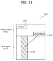
- FIG. 11 shows control information transmission according to an embodiment of the present invention.
- a sub frame 2000 includes a control region 2001, a data region 2002, and an extended control region 2003.
- the extended control region 2003 is used to monitor some PDCCHs of the existing data region.
- a CFI for reporting a size of the control region 2001 is transmitted through a PCFICH 2010.
- a cross-CFI and/or extended control information regarding the extended control region 2003 are transmitted through a common PDCCH 2020.
- the common PDCCH 2020 can be transmitted in a predetermined resource without having to use blind decoding.
- a dedicated identifier can be used in CRC masking.
- the extended identifier can be UE specific, or can be UE group specific or cell specific.
- An identifier such as the existing C-RNTI can be reused as the extended identifier.
- Blind decoding can be used in the common PDCCH 202 similarly to the PDCCH.
- a search space in which the E-PCFICH 1020 is searched can be limited. It can be limited to a UE-specific search space or a common search space, or a new extended search space can be defined. Alternatively, a start point of the search space of the E-PCFICH 1020 can be fixed. The number of CCE aggregation levels used for detection of the E-PCFICH 1020 can also be limited.
- a DCI format used in the E-PCFICH 1020 can be predetermined.
- the UE receives the PDSCH in the remaining parts other than the extended control region.
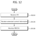
- FIG. 12 is a flowchart showing a control channel monitoring method according to an embodiment of the present invention.
- a UE receives a CFI indicating a size of a control region in a sub frame through a PCFICH (step S1110).
- the UE receives extended control information regarding an extended control region in the subframe through an E-PCFICH (or common PDCCH) in the control region (step S1120).
- the UE can receive the extended control information through the E-PCFICH according to the embodiment of FIG. 10 and/or the common PDCCH according to the embodiment of FIG. 11 .
- the UE monitors a PDCCH in the control region and the extended control region (step S1130).
- FIG. 13 is a block diagram showing a wireless communication system according to an embodiment of the present invention.
- a BS 50 includes a processor 51, a memory 52, and a radio frequency (RF) unit 53.
- the memory 52 is coupled to the processor 51, and stores a variety of information for driving the processor 51.
- the RF unit 53 is coupled to the processor 51, and transmits and/or receives a radio signal.
- the processor 51 implements the proposed functions, procedures, and/or methods.
- the processor 51 can implement an operation of the BS 50 according to the embodiments of FIG. 10 and FIG. 12 .
- a UE 60 includes a processor 61, a memory 62, and an RF unit 63.
- the memory 62 is coupled to the processor 61, and stores a variety of information for driving the processor 61.
- the RF unit 63 is coupled to the processor 61, and transmits and/or receives a radio signal.
- the processor 61 implements the proposed functions, procedures, and/or methods.
- the processor 51 can implement an operation of the UE 60 according to the embodiments of FIG. 10 and FIG. 12 .
- the processor may include Application-Specific Integrated Circuits (ASICs), other chipsets, logic circuits, and/or data processors.
- the memory may include Read-Only Memory (ROM), Random Access Memory (RAM), flash memory, memory cards, storage media and/or other storage devices.
- the RF unit may include a baseband circuit for processing a radio signal.
- the above-described scheme may be implemented using a module (process or function) which performs the above function.
- the module may be stored in the memory and executed by the processor.
- the memory may be disposed to the processor internally or externally and connected to the processor using a variety of well-known means.
Landscapes
- Engineering & Computer Science (AREA)
- Computer Networks & Wireless Communication (AREA)
- Signal Processing (AREA)
- Mobile Radio Communication Systems (AREA)
Claims (10)
- Procédé de surveillance d'un canal de contrôle dans un système de communication sans fil, le procédé comprenant :la réception d'un indicateur de format de contrôle, CFI, indiquant une taille d'une région de contrôle dans une sous-trame par l'intermédiaire d'un premier canal physique de contrôle en voie descendante ;la détermination du fait qu'une région de contrôle étendu est présente dans la sous-trame si le CFI indique une taille maximale de la région de contrôle ; etla surveillance d'un canal physique de contrôle en voie descendante, PDCCH, dans la région de contrôle et la région de contrôle étendu si une région de contrôle étendu a été déterminée comme étant présente dans la sous-trame.
- Procédé selon la revendication 1, comprenant en outre :la réception d'informations de contrôle étendu concernant la région de contrôle étendu dans la sous-trame par l'intermédiaire d'un second canal de contrôle en voie descendante dans la région de contrôle.
- Procédé selon la revendication 2, dans lequel les informations de contrôle étendu comportent des informations d'attribution de ressource concernant une ressource à laquelle la région de contrôle étendu est attribuée.
- Procédé selon la revendication 2, dans lequel les informations de contrôle étendu comportent un CFI croisé indiquant une taille d'une région de contrôle dans une sous-trame d'une autre porteuse composante.
- Procédé selon la revendication 1, dans lequel le premier canal de contrôle en voie descendante est un canal physique d'indicateur de format de contrôle, PCFICH.
- Procédé selon la revendication 1, dans lequel le second canal de contrôle en voie descendante est détecté par décodage aveugle.
- Equipement d'utilisateur (60) configuré pour surveiller un canal de contrôle dans un système de communication sans fil, l'équipement d'utilisateur (60) comprenant :une unité radiofréquence, RF, (63) configurée pour transmettre et recevoir un signal radio ; etun processeur (61) couplé à l'unité RF (63), dans lequel le processeur (61) est configuré pour :recevoir un indicateur de format de contrôle, CFI, indiquant une taille d'une région de contrôle dans une sous-trame par l'intermédiaire d'un premier canal de contrôle en voie descendante;déterminer le fait qu'une région de contrôle étendu est présente dans la sous-trame si le CFI indique une taille maximale de la région de contrôle ; etsurveiller un canal physique de contrôle en voie descendante, PDCCH, dans la région de contrôle et la région de contrôle étendu si une région de contrôle étendu a été déterminée comme étant présente dans la sous-trame.
- Equipement d'utilisateur (60) selon la revendication 7, dans lequel le processeur (61) est configuré pour recevoir des informations de contrôle étendu concernant la région de contrôle étendu dans la sous-trame par l'intermédiaire d'un second canal de contrôle en voie descendante dans la région de contrôle.
- Equipement d'utilisateur (60) selon la revendication 8, dans lequel les informations de contrôle étendu comportent des informations d'attribution de ressource concernant une ressource à laquelle la région de contrôle étendu est attribuée.
- Equipement d'utilisateur (60) selon la revendication 7, dans lequel le premier canal de contrôle en voie descendante est un canal physique d'indicateur de format de contrôle, PCFICH.
Applications Claiming Priority (2)
| Application Number | Priority Date | Filing Date | Title |
|---|---|---|---|
| US28637809P | 2009-12-15 | 2009-12-15 | |
| PCT/KR2010/008965 WO2011074868A2 (fr) | 2009-12-15 | 2010-12-15 | Procédé et dispositif permettant de surveiller un canal de commande dans un système de communication sans fil |
Publications (3)
| Publication Number | Publication Date |
|---|---|
| EP2515571A2 EP2515571A2 (fr) | 2012-10-24 |
| EP2515571A4 EP2515571A4 (fr) | 2014-01-08 |
| EP2515571B1 true EP2515571B1 (fr) | 2016-11-16 |
Family
ID=44167861
Family Applications (1)
| Application Number | Title | Priority Date | Filing Date |
|---|---|---|---|
| EP10837864.7A Not-in-force EP2515571B1 (fr) | 2009-12-15 | 2010-12-15 | Procédé et dispositif permettant de surveiller un canal de commande dans un système de communication sans fil |
Country Status (3)
| Country | Link |
|---|---|
| US (1) | US9294934B2 (fr) |
| EP (1) | EP2515571B1 (fr) |
| WO (1) | WO2011074868A2 (fr) |
Families Citing this family (19)
| Publication number | Priority date | Publication date | Assignee | Title |
|---|---|---|---|---|
| WO2011000440A1 (fr) * | 2009-07-03 | 2011-01-06 | Nokia Siemens Networks Oy | Extension de couverture de canal de commande de liaison descendante physique |
| US9450729B2 (en) * | 2011-06-15 | 2016-09-20 | Lg Electronics Inc. | Method and device for allocating a downlink control channel in a wireless communication system |
| WO2013009088A2 (fr) * | 2011-07-12 | 2013-01-17 | Lg Electronics Inc. | Procédé permettant à un équipement utilisateur de rechercher des informations de commande dans un système multinœud et appareil l'utilisant |
| KR20140053087A (ko) | 2011-07-27 | 2014-05-07 | 엘지전자 주식회사 | 무선통신시스템에서 시퀀스 매핑 방법 및 장치 |
| KR101578012B1 (ko) | 2011-07-28 | 2015-12-28 | 엘지전자 주식회사 | 무선 접속 시스템에서 하향링크 제어정보 송수신 방법 및 이를 위한 단말 |
| KR20130017243A (ko) * | 2011-08-10 | 2013-02-20 | 주식회사 팬택 | 무선통신 시스템에서 제어채널의 전송 장치 및 방법 |
| JP2013055393A (ja) * | 2011-09-01 | 2013-03-21 | Sony Corp | 通信装置、通信方法、通信システムおよび基地局 |
| US8971250B2 (en) | 2011-10-29 | 2015-03-03 | Ofinno Technologies, Llc | Special subframe allocation |
| US8937918B2 (en) | 2011-10-29 | 2015-01-20 | Ofinno Technologies, Llc | Efficient special subframe allocation |
| US11696300B2 (en) | 2011-10-29 | 2023-07-04 | Comcast Cable Communications, Llc | Configuration of reduced transmission power time intervals based on traffic load |
| US8873467B2 (en) | 2011-12-05 | 2014-10-28 | Ofinno Technologies, Llc | Control channel detection |
| US8934436B2 (en) | 2011-12-31 | 2015-01-13 | Ofinno Technologies, L.L.C. | Special subframe configuration in wireless networks |
| WO2013129802A1 (fr) * | 2012-02-28 | 2013-09-06 | 엘지전자 주식회사 | Procédé et appareil de surveillance de canal de commande de liaison descendante dans un système de communication sans fil |
| US9654260B2 (en) | 2012-03-15 | 2017-05-16 | Lg Electronics Inc. | Method for setting start symbol of downlink channel in wireless communication system and apparatus for same |
| KR20150082222A (ko) | 2012-11-06 | 2015-07-15 | 엘지전자 주식회사 | 무선 통신 시스템에서 제어 정보를 검출하는 방법 및 이를 위한 장치 |
| WO2014110793A1 (fr) * | 2013-01-18 | 2014-07-24 | 华为技术有限公司 | Procédé destiné à l'envoi d'informations de commande, station de base et équipement utilisateur |
| US10404441B2 (en) | 2014-11-11 | 2019-09-03 | Electronics And Telecommunications Research Institute | Method and apparatus for configuring transmission time interval in mobile communication system |
| US10484127B2 (en) * | 2015-01-30 | 2019-11-19 | Lg Electronics Inc. | Method and apparatus for tranceiving common control message in wireless access system supporting narrow band internet of things |
| KR20180010949A (ko) | 2016-07-21 | 2018-01-31 | 삼성전자주식회사 | 무선 셀룰라 통신 시스템에서 다수의 dmrs 구조에 대한 설정 방법 및 장치 |
Family Cites Families (6)
| Publication number | Priority date | Publication date | Assignee | Title |
|---|---|---|---|---|
| KR20080084533A (ko) | 2007-03-16 | 2008-09-19 | 엘지전자 주식회사 | 이동통신 시스템에서의 데이터 통신 방법 |
| KR20080097112A (ko) * | 2007-04-30 | 2008-11-04 | 엘지전자 주식회사 | 제어영역 포맷정보를 전송하는 방법 |
| KR101448309B1 (ko) * | 2007-09-28 | 2014-10-08 | 엘지전자 주식회사 | 무선통신 시스템에서 하향링크 제어채널 모니터링 방법 |
| KR101808671B1 (ko) * | 2007-12-20 | 2017-12-13 | 옵티스 와이어리스 테크놀로지, 엘엘씨 | 전기통신 시스템에서의 방법 및 장치 |
| US20110205995A1 (en) * | 2008-10-28 | 2011-08-25 | Nokia Corporation | Physical downlink control channel configuration for extended bandwidth systems |
| KR101667826B1 (ko) * | 2008-11-04 | 2016-10-19 | 애플 인크. | 제 1 캐리어에서 제 2, 다른 캐리어에서의 제어 정보를 표시하기 위해 다운링크 제어 구조를 제공하는 방법 |
-
2010
- 2010-12-15 EP EP10837864.7A patent/EP2515571B1/fr not_active Not-in-force
- 2010-12-15 WO PCT/KR2010/008965 patent/WO2011074868A2/fr not_active Ceased
- 2010-12-15 US US13/516,066 patent/US9294934B2/en not_active Expired - Fee Related
Also Published As
| Publication number | Publication date |
|---|---|
| WO2011074868A2 (fr) | 2011-06-23 |
| EP2515571A4 (fr) | 2014-01-08 |
| US20120294248A1 (en) | 2012-11-22 |
| EP2515571A2 (fr) | 2012-10-24 |
| US9294934B2 (en) | 2016-03-22 |
| WO2011074868A3 (fr) | 2011-11-17 |
Similar Documents
| Publication | Publication Date | Title |
|---|---|---|
| EP2515571B1 (fr) | Procédé et dispositif permettant de surveiller un canal de commande dans un système de communication sans fil | |
| EP2404398B1 (fr) | Supervision des canaux de contrôle dans un système de communication utilisant des porteuses multiples | |
| EP2683098B1 (fr) | Procédé et appareil pour amener un terminal à rechercher des données de contrôle dans un système multi-noeud | |
| EP3629503B1 (fr) | Procédé d'émission ou de réception de signal dans un système de communication sans fil et appareil associé | |
| EP3471297B1 (fr) | Procédé et dispositif pour recevoir/transmettre un canal de control dans coreset | |
| US8441996B2 (en) | Method and apparatus for monitoring control channel in multiple carrier system | |
| KR101777416B1 (ko) | 반송파 집성 시스템에서 단말의 통신 방법 및 단말 | |
| EP2822339B1 (fr) | Procédé et appareil pour attribuer des ressources dans un système de communication sans fil | |
| EP2341679B1 (fr) | Procédé et dispositif de communication dans un système à porteuses multiples | |
| EP3407525B1 (fr) | Procédé et dispositif de réglage d'un canal de commande et d'un canal de données dans un système de communication sans fil | |
| US9497775B2 (en) | Method and apparatus for carrier scheduling in a multi-carrier system | |
| US8780833B2 (en) | Control channel monitoring apparatus in multi-carrier system and method thereof | |
| US8885556B2 (en) | Method for performing a HARQ in a multiple carrier system | |
| US8867441B2 (en) | Wireless apparatus for a multi-carrier system | |
| KR101670517B1 (ko) | 반송파 집성 시스템에서 상향링크의 교차 반송파 스케줄링 방법 및 단말 | |
| US10057032B2 (en) | Method and device for transmitting data for half-duplex device | |
| EP2557710A2 (fr) | Procédé et appareil de surveillance de canal pdcch dans un système de ligne de jonction de porteuse | |
| US20120039180A1 (en) | Apparatus and method for monitoring control channel in multi-carrier system | |
| US20120087331A1 (en) | Resource mapping method and apparatus in wireless communication system | |
| WO2013009088A2 (fr) | Procédé permettant à un équipement utilisateur de rechercher des informations de commande dans un système multinœud et appareil l'utilisant | |
| KR101601288B1 (ko) | 다중 반송파 시스템에서 제어채널을 모니터링하는 장치 및 방법 | |
| EP2482507A2 (fr) | Procédé et appareil de réception de données de liaison descendante dans un système à porteuses multiples | |
| US9549399B2 (en) | Method and apparatus for monitoring downlink control channel |
Legal Events
| Date | Code | Title | Description |
|---|---|---|---|
| PUAI | Public reference made under article 153(3) epc to a published international application that has entered the european phase |
Free format text: ORIGINAL CODE: 0009012 |
|
| 17P | Request for examination filed |
Effective date: 20120710 |
|
| AK | Designated contracting states |
Kind code of ref document: A2 Designated state(s): AL AT BE BG CH CY CZ DE DK EE ES FI FR GB GR HR HU IE IS IT LI LT LU LV MC MK MT NL NO PL PT RO RS SE SI SK SM TR |
|
| DAX | Request for extension of the european patent (deleted) | ||
| A4 | Supplementary search report drawn up and despatched |
Effective date: 20131211 |
|
| RIC1 | Information provided on ipc code assigned before grant |
Ipc: H04W 24/02 20090101AFI20131205BHEP |
|
| 17Q | First examination report despatched |
Effective date: 20150508 |
|
| GRAP | Despatch of communication of intention to grant a patent |
Free format text: ORIGINAL CODE: EPIDOSNIGR1 |
|
| INTG | Intention to grant announced |
Effective date: 20160527 |
|
| GRAS | Grant fee paid |
Free format text: ORIGINAL CODE: EPIDOSNIGR3 |
|
| GRAA | (expected) grant |
Free format text: ORIGINAL CODE: 0009210 |
|
| AK | Designated contracting states |
Kind code of ref document: B1 Designated state(s): AL AT BE BG CH CY CZ DE DK EE ES FI FR GB GR HR HU IE IS IT LI LT LU LV MC MK MT NL NO PL PT RO RS SE SI SK SM TR |
|
| REG | Reference to a national code |
Ref country code: GB Ref legal event code: FG4D |
|
| REG | Reference to a national code |
Ref country code: CH Ref legal event code: EP |
|
| REG | Reference to a national code |
Ref country code: IE Ref legal event code: FG4D |
|
| REG | Reference to a national code |
Ref country code: AT Ref legal event code: REF Ref document number: 846917 Country of ref document: AT Kind code of ref document: T Effective date: 20161215 |
|
| REG | Reference to a national code |
Ref country code: FR Ref legal event code: PLFP Year of fee payment: 7 |
|
| REG | Reference to a national code |
Ref country code: DE Ref legal event code: R096 Ref document number: 602010038130 Country of ref document: DE |
|
| PG25 | Lapsed in a contracting state [announced via postgrant information from national office to epo] |
Ref country code: LV Free format text: LAPSE BECAUSE OF FAILURE TO SUBMIT A TRANSLATION OF THE DESCRIPTION OR TO PAY THE FEE WITHIN THE PRESCRIBED TIME-LIMIT Effective date: 20161116 |
|
| REG | Reference to a national code |
Ref country code: NL Ref legal event code: MP Effective date: 20161116 |
|
| REG | Reference to a national code |
Ref country code: LT Ref legal event code: MG4D |
|
| REG | Reference to a national code |
Ref country code: AT Ref legal event code: MK05 Ref document number: 846917 Country of ref document: AT Kind code of ref document: T Effective date: 20161116 |
|
| PG25 | Lapsed in a contracting state [announced via postgrant information from national office to epo] |
Ref country code: GR Free format text: LAPSE BECAUSE OF FAILURE TO SUBMIT A TRANSLATION OF THE DESCRIPTION OR TO PAY THE FEE WITHIN THE PRESCRIBED TIME-LIMIT Effective date: 20170217 Ref country code: NO Free format text: LAPSE BECAUSE OF FAILURE TO SUBMIT A TRANSLATION OF THE DESCRIPTION OR TO PAY THE FEE WITHIN THE PRESCRIBED TIME-LIMIT Effective date: 20170216 Ref country code: SE Free format text: LAPSE BECAUSE OF FAILURE TO SUBMIT A TRANSLATION OF THE DESCRIPTION OR TO PAY THE FEE WITHIN THE PRESCRIBED TIME-LIMIT Effective date: 20161116 Ref country code: NL Free format text: LAPSE BECAUSE OF FAILURE TO SUBMIT A TRANSLATION OF THE DESCRIPTION OR TO PAY THE FEE WITHIN THE PRESCRIBED TIME-LIMIT Effective date: 20161116 Ref country code: LT Free format text: LAPSE BECAUSE OF FAILURE TO SUBMIT A TRANSLATION OF THE DESCRIPTION OR TO PAY THE FEE WITHIN THE PRESCRIBED TIME-LIMIT Effective date: 20161116 |
|
| PG25 | Lapsed in a contracting state [announced via postgrant information from national office to epo] |
Ref country code: ES Free format text: LAPSE BECAUSE OF FAILURE TO SUBMIT A TRANSLATION OF THE DESCRIPTION OR TO PAY THE FEE WITHIN THE PRESCRIBED TIME-LIMIT Effective date: 20161116 Ref country code: HR Free format text: LAPSE BECAUSE OF FAILURE TO SUBMIT A TRANSLATION OF THE DESCRIPTION OR TO PAY THE FEE WITHIN THE PRESCRIBED TIME-LIMIT Effective date: 20161116 Ref country code: FI Free format text: LAPSE BECAUSE OF FAILURE TO SUBMIT A TRANSLATION OF THE DESCRIPTION OR TO PAY THE FEE WITHIN THE PRESCRIBED TIME-LIMIT Effective date: 20161116 Ref country code: AT Free format text: LAPSE BECAUSE OF FAILURE TO SUBMIT A TRANSLATION OF THE DESCRIPTION OR TO PAY THE FEE WITHIN THE PRESCRIBED TIME-LIMIT Effective date: 20161116 Ref country code: PT Free format text: LAPSE BECAUSE OF FAILURE TO SUBMIT A TRANSLATION OF THE DESCRIPTION OR TO PAY THE FEE WITHIN THE PRESCRIBED TIME-LIMIT Effective date: 20170316 Ref country code: RS Free format text: LAPSE BECAUSE OF FAILURE TO SUBMIT A TRANSLATION OF THE DESCRIPTION OR TO PAY THE FEE WITHIN THE PRESCRIBED TIME-LIMIT Effective date: 20161116 Ref country code: BE Free format text: LAPSE BECAUSE OF NON-PAYMENT OF DUE FEES Effective date: 20161231 Ref country code: PL Free format text: LAPSE BECAUSE OF FAILURE TO SUBMIT A TRANSLATION OF THE DESCRIPTION OR TO PAY THE FEE WITHIN THE PRESCRIBED TIME-LIMIT Effective date: 20161116 |
|
| REG | Reference to a national code |
Ref country code: DE Ref legal event code: R119 Ref document number: 602010038130 Country of ref document: DE |
|
| PG25 | Lapsed in a contracting state [announced via postgrant information from national office to epo] |
Ref country code: DK Free format text: LAPSE BECAUSE OF FAILURE TO SUBMIT A TRANSLATION OF THE DESCRIPTION OR TO PAY THE FEE WITHIN THE PRESCRIBED TIME-LIMIT Effective date: 20161116 Ref country code: SK Free format text: LAPSE BECAUSE OF FAILURE TO SUBMIT A TRANSLATION OF THE DESCRIPTION OR TO PAY THE FEE WITHIN THE PRESCRIBED TIME-LIMIT Effective date: 20161116 Ref country code: EE Free format text: LAPSE BECAUSE OF FAILURE TO SUBMIT A TRANSLATION OF THE DESCRIPTION OR TO PAY THE FEE WITHIN THE PRESCRIBED TIME-LIMIT Effective date: 20161116 Ref country code: RO Free format text: LAPSE BECAUSE OF FAILURE TO SUBMIT A TRANSLATION OF THE DESCRIPTION OR TO PAY THE FEE WITHIN THE PRESCRIBED TIME-LIMIT Effective date: 20161116 Ref country code: CZ Free format text: LAPSE BECAUSE OF FAILURE TO SUBMIT A TRANSLATION OF THE DESCRIPTION OR TO PAY THE FEE WITHIN THE PRESCRIBED TIME-LIMIT Effective date: 20161116 |
|
| REG | Reference to a national code |
Ref country code: CH Ref legal event code: PL |
|
| PG25 | Lapsed in a contracting state [announced via postgrant information from national office to epo] |
Ref country code: BE Free format text: LAPSE BECAUSE OF FAILURE TO SUBMIT A TRANSLATION OF THE DESCRIPTION OR TO PAY THE FEE WITHIN THE PRESCRIBED TIME-LIMIT Effective date: 20161116 Ref country code: BG Free format text: LAPSE BECAUSE OF FAILURE TO SUBMIT A TRANSLATION OF THE DESCRIPTION OR TO PAY THE FEE WITHIN THE PRESCRIBED TIME-LIMIT Effective date: 20170216 Ref country code: IT Free format text: LAPSE BECAUSE OF FAILURE TO SUBMIT A TRANSLATION OF THE DESCRIPTION OR TO PAY THE FEE WITHIN THE PRESCRIBED TIME-LIMIT Effective date: 20161116 Ref country code: SM Free format text: LAPSE BECAUSE OF FAILURE TO SUBMIT A TRANSLATION OF THE DESCRIPTION OR TO PAY THE FEE WITHIN THE PRESCRIBED TIME-LIMIT Effective date: 20161116 |
|
| PLBE | No opposition filed within time limit |
Free format text: ORIGINAL CODE: 0009261 |
|
| STAA | Information on the status of an ep patent application or granted ep patent |
Free format text: STATUS: NO OPPOSITION FILED WITHIN TIME LIMIT |
|
| PG25 | Lapsed in a contracting state [announced via postgrant information from national office to epo] |
Ref country code: MC Free format text: LAPSE BECAUSE OF FAILURE TO SUBMIT A TRANSLATION OF THE DESCRIPTION OR TO PAY THE FEE WITHIN THE PRESCRIBED TIME-LIMIT Effective date: 20161116 |
|
| REG | Reference to a national code |
Ref country code: IE Ref legal event code: MM4A |
|
| 26N | No opposition filed |
Effective date: 20170817 |
|
| GBPC | Gb: european patent ceased through non-payment of renewal fee |
Effective date: 20170216 |
|
| PG25 | Lapsed in a contracting state [announced via postgrant information from national office to epo] |
Ref country code: CH Free format text: LAPSE BECAUSE OF NON-PAYMENT OF DUE FEES Effective date: 20161231 Ref country code: LI Free format text: LAPSE BECAUSE OF NON-PAYMENT OF DUE FEES Effective date: 20161231 Ref country code: LU Free format text: LAPSE BECAUSE OF NON-PAYMENT OF DUE FEES Effective date: 20161215 |
|
| REG | Reference to a national code |
Ref country code: FR Ref legal event code: PLFP Year of fee payment: 8 |
|
| PG25 | Lapsed in a contracting state [announced via postgrant information from national office to epo] |
Ref country code: DE Free format text: LAPSE BECAUSE OF NON-PAYMENT OF DUE FEES Effective date: 20170701 Ref country code: SI Free format text: LAPSE BECAUSE OF FAILURE TO SUBMIT A TRANSLATION OF THE DESCRIPTION OR TO PAY THE FEE WITHIN THE PRESCRIBED TIME-LIMIT Effective date: 20161116 Ref country code: IE Free format text: LAPSE BECAUSE OF NON-PAYMENT OF DUE FEES Effective date: 20161215 |
|
| PGFP | Annual fee paid to national office [announced via postgrant information from national office to epo] |
Ref country code: FR Payment date: 20171110 Year of fee payment: 8 |
|
| PG25 | Lapsed in a contracting state [announced via postgrant information from national office to epo] |
Ref country code: GB Free format text: LAPSE BECAUSE OF NON-PAYMENT OF DUE FEES Effective date: 20170216 |
|
| PG25 | Lapsed in a contracting state [announced via postgrant information from national office to epo] |
Ref country code: CY Free format text: LAPSE BECAUSE OF FAILURE TO SUBMIT A TRANSLATION OF THE DESCRIPTION OR TO PAY THE FEE WITHIN THE PRESCRIBED TIME-LIMIT Effective date: 20161116 Ref country code: HU Free format text: LAPSE BECAUSE OF FAILURE TO SUBMIT A TRANSLATION OF THE DESCRIPTION OR TO PAY THE FEE WITHIN THE PRESCRIBED TIME-LIMIT; INVALID AB INITIO Effective date: 20101215 |
|
| PG25 | Lapsed in a contracting state [announced via postgrant information from national office to epo] |
Ref country code: TR Free format text: LAPSE BECAUSE OF FAILURE TO SUBMIT A TRANSLATION OF THE DESCRIPTION OR TO PAY THE FEE WITHIN THE PRESCRIBED TIME-LIMIT Effective date: 20161116 Ref country code: MK Free format text: LAPSE BECAUSE OF FAILURE TO SUBMIT A TRANSLATION OF THE DESCRIPTION OR TO PAY THE FEE WITHIN THE PRESCRIBED TIME-LIMIT Effective date: 20161116 Ref country code: IS Free format text: LAPSE BECAUSE OF FAILURE TO SUBMIT A TRANSLATION OF THE DESCRIPTION OR TO PAY THE FEE WITHIN THE PRESCRIBED TIME-LIMIT Effective date: 20161116 |
|
| PG25 | Lapsed in a contracting state [announced via postgrant information from national office to epo] |
Ref country code: MT Free format text: LAPSE BECAUSE OF NON-PAYMENT OF DUE FEES Effective date: 20161215 |
|
| PG25 | Lapsed in a contracting state [announced via postgrant information from national office to epo] |
Ref country code: FR Free format text: LAPSE BECAUSE OF NON-PAYMENT OF DUE FEES Effective date: 20181231 |
|
| PG25 | Lapsed in a contracting state [announced via postgrant information from national office to epo] |
Ref country code: AL Free format text: LAPSE BECAUSE OF FAILURE TO SUBMIT A TRANSLATION OF THE DESCRIPTION OR TO PAY THE FEE WITHIN THE PRESCRIBED TIME-LIMIT Effective date: 20161116 |